Fast and Accurate Antenna Alignment Correction Performed Using a ...
Fast and Accurate Antenna Alignment Correction Performed Using a ...
Fast and Accurate Antenna Alignment Correction Performed Using a ...
Create successful ePaper yourself
Turn your PDF publications into a flip-book with our unique Google optimized e-Paper software.
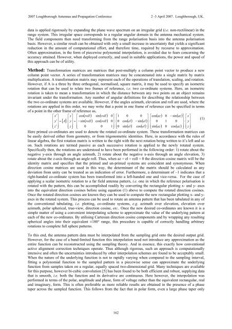
2007 Loughborough <strong>Antenna</strong>s <strong>and</strong> Propagation Conference 2 -3 April 2007. Loughborough, UK.data is applied rigorously by exp<strong>and</strong>ing the plane wave spectrum on an irregular grid (i.e. non-rectilinear) in therange system. This irregular space corresponds to a regular angular domain in the antenna mechanical system.The field components then need transforming from the range polarisation basis into the antenna polarisationbasis. However, a similar result can be obtained with only a small increase in uncertainty that yields a significantreduction in the amount of computational effort, <strong>and</strong> therefore time, required by recourse to approximation.Often approximation, in the form of piecewise polynomial interpolation, is avoided due to fears concerning theaccuracy attained. However, when deployed correctly, <strong>and</strong> used in suitable applications, the power <strong>and</strong> speed ofthis approach can be of utility.Method: Transformation matrices are matrices that post-multiply a column point vector to produce a newcolumn point vector. A series of transformation matrices may be concatenated into a single matrix by matrixmultiplication. A transformation matrix may represent each of the operations of translation, scaling, <strong>and</strong> rotation.However, if A is a three by three orthogonal, normalised, square matrix, it may be used to specify an isometricrotation that can be used to relate two frames of reference, i.e. two co-ordinate systems. Here, an isometricrotation is taken to mean a transformation in which the distance between any two points on an object remainsinvariant under the transformation. Any number of angular definitions for describing the relationship betweenthe two co-ordinate systems are available. However, if the angles azimuth, elevation <strong>and</strong> roll are used, where therotations are applied in this order, we may write that a point in one frame of reference can be specified in termsof a point in the other frame of reference as,⎡x′⎤ ⎡x⎤⎡ cos( roll) sin( roll)0⎤⎡10 0 ⎤ ⎡cos( az) 0 − sin( az)⎤ ⎡x⎤⎢ ⎥[ ]⎢ ⎥ ⎢( ) ( )⎥⋅⎢( ) ( )⎥⋅⎢⎥⋅⎢ (1)⎢y′⎥= A ⋅⎢y⎥=⎢− sin roll cos roll 0⎥ ⎢0 cos el − sin el⎥ ⎢0 1 0⎥ ⎢y⎢ ⎥ ⎢ ⎥ ⎢⎥ ⎢ ( ) ( ) ⎥ ⎢ ( ) ( ) ⎥ ⎢ ⎥ ⎥⎥ ⎣z′⎦ ⎣z⎦⎣ 0 0 1⎦⎣0sin el cos el ⎦ ⎣sinaz 0 cos az ⎦ ⎣z⎦Here primed co-ordinates are used to denote the rotated co-ordinate system. These transformation matrices canbe easily derived either from geometry, or from trigonometric identities. Here, in accordance with the rules oflinear algebra, the first rotation matrix is written to the right with the next rotation being written to it’s left <strong>and</strong> soon. Such rotations are termed passive as each successive rotation is applied to the newly rotated system.Specifically then, the rotations are understood to have been performed in the following order: 1) rotate about thenegative y-axis through an angle azimuth, 2) rotate about the negative x-axis through an angle elevation, 3)rotate about the z-axis through an angle roll. Thus, when az = el = roll = 0 the direction cosine matrix will be theidentity matrix <strong>and</strong> specifies that the primed <strong>and</strong> un-primed systems are coincident <strong>and</strong> synonymous. Whendirection cosine matrices are used in this way, the determinant of the matrix should be calculated as anydeviation from unity can be treated as an indication of error. Furthermore, a determinant of –1 indicates that aright-h<strong>and</strong>ed co-ordinate system has been transformed into a left-h<strong>and</strong>ed one <strong>and</strong> vice-versa. For the case ofapplying a scalar isometric rotation to a far field antenna pattern, i.e. one in which the reference polarisation isrotated with the pattern, this can be accomplished readily by converting the rectangular plotting x- <strong>and</strong> y- axesinto the equivalent direction cosines before using equation (1) above to compute the rotated direction cosines.Once the rotated direction cosines are known they can be used to compute the new rectangular plotting x- <strong>and</strong> y-axes in the rotated system. This process can be used to rotate an antenna pattern that has been tabulated in any ofthe conventional tabulating, i.e. plotting, co-ordinate systems, e.g. azimuth over elevation, elevation overazimuth, polar spherical, true-view, direction cosine, etc.. Once the new desired co-ordinates are known it is asimple matter of using a convenient interpolating scheme to approximate the value of the underlying pattern ateach of the new co-ordinates. By utilising Cartesian direction cosine components <strong>and</strong> by wrapping any resultingspherical angles into their equivalent ±180° range, this procedure is capable of correctly h<strong>and</strong>ling arbitraryrotations to complete full sphere patterns.To this end, the antenna pattern data must be interpolated from the sampling grid onto the desired output grid.However, for the case of a b<strong>and</strong>-limited function this interpolation need not introduce any approximation as theentire function can be reconstructed using the sampling theory. And in essence, this exactly how conventionalactive alignment correction techniques operate. Thus although rigorous, such an approach is computationallyintensive <strong>and</strong> often the uncertainties introduced by other interpolation schemes are found to be acceptably small.When the nature of the underlying function is not to rapidly varying when compared to the sampling interval,fitting a polynomial function to the sampled pattern in a piecewise sense can approximate the underlyingfunction from samples taken on a regular, equally spaced two-dimensional grid. Many techniques are availablefor this purpose, however bi-cubic convolution [5] has been found to be both efficient <strong>and</strong> robust, supplying datathat is smooth, i.e. both the function <strong>and</strong> its derivative are continuous. Here however, the interpolation wasperformed in terms of the polar, amplitude <strong>and</strong> phase, form of voltage rather than the equivalent rectangular, real<strong>and</strong> imaginary, form. This is often preferable as more reliable results are obtained in the presence of a phasetaper across the sampled function. This follows from the fact that in polar form, even a large phase taper only162


