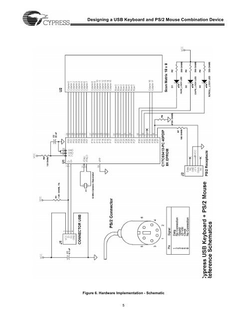
<strong>Designing</strong> a <strong>USB</strong> <strong>Keyboard</strong> <strong>and</strong> <strong>PS</strong>/2 <strong>Mouse</strong> <strong>Combination</strong> <strong>Device</strong>Ports 0 to 2 offer low current drive with a typical current sinkcapability of 7 mA. Port 3 offers a higher current drive, with atypical current sink of 12 mA which can be used to drive LEDs.Each General Purpose I/O (GPIO) is capable of generatingan interrupt to the RISC core. Interrupt polarity is selectableon a per port basis using the GPIO Configuration Register(see Table 3 above.) Selecting a negative polarity (“–”) willcause falling edges to trigger an interrupt, while a positivepolarity (“+”) selects rising edges as triggers. The interrupttriggered by a GPIO line is individually enabled by a dedicatedbit in the Interrupt Enable Register. All GPIO interrupts arefurther masked by the Global GPIO Interrupt Enable Bit in theGlobal Interrupt Enable Register.The GPIO Configuration Register is located at I/O address0x08. The Data Registers are located at I/O addresses 0x00to 0x03 for Port 0 to Port 3 respectively.Power-up ModeThe CY7C63413 offers 2 modes of operation after a power-on-reset(POR) event: suspend-on-reset (typical for a <strong>USB</strong>application) <strong>and</strong> run-on-reset (typical for a non-<strong>USB</strong> application).The suspend-on-reset mode is selected by attaching apull-up resistor (100 to 470 KΩ) to V CC on Bit 7 of GPIO Port3. The run-on-reset mode is selected by attaching a pull-downresistor (0 to 470 KΩ) to ground on Bit 7 of GPIO Port 3. SeeFigure 4. As the <strong>USB</strong> keyboard <strong>and</strong> <strong>PS</strong>/2 mouse combinationdevice is a <strong>USB</strong> implementation, the CY7C63413 should beconfigured for suspend-on-reset.Port 2 is configured as resistive inputs (7 Kohm pull-ups toV CC ), <strong>and</strong> are connected to the M rows of the scan matrix (upto 8 rows are supported). Ports 0, 1, <strong>and</strong> 3 are configured asopen drain outputs, <strong>and</strong> are used to connect to the N columnsof the scan matrix, the 3 LEDs (Num Lock, Caps Lock, <strong>and</strong>Scroll Lock), <strong>and</strong> the two <strong>PS</strong>/2 mouse signals. Since the <strong>PS</strong>/2signals occupy two bits of Port 3, we can only support keyboardscan matrices up to 18 columns. Most of the existingAT-101 or AT-104 type keyboards do not use more than 18columns. For keyboards that use scan matrices with morethan 18 columns, it is usually possible to relocate the keysfrom the columns 19 <strong>and</strong> greater to unassigned locations oncolumns 18 or below. The three LEDs are connected to thelower three bits of Port 3 as well (for high current drive). Forscan matrices with less then 8 rows or 18 columns, the unusedport bits should be left unconnected.The <strong>PS</strong>/2 signals are connected to the <strong>PS</strong>/2 mouse througha 6-pin <strong>PS</strong>/2 receptacle. +5V <strong>and</strong> GND are also available onthe receptacle to power the <strong>PS</strong>/2 mouse. The strap optionpull-up resistor R8 (470 KΩ) selects the Suspend-On-Resetmode for the <strong>USB</strong> microcontroller, <strong>and</strong> the series terminationresistor R7 (100Ω) is used to reduce crosstalk problems overthe <strong>PS</strong>/2 lines.During a keyboard scan test where no key is pressed, the rowport data bits will be HIGH since all row lines are internallypulled up to V CC . When a key is pressed, driving its columnport line LOW (key scan pattern) will cause its row line to goLOW as well. See Figure 5.VCCPort 3, Bit 7Rpullup100 100K to to 470 470K KΩOHMFigure 4. (a) Suspend-On-Reset ModeRow Port LineRow iColumn jColumn Port LinePort 3, Bit 7Closed when key i,j is pressedDriven LOW by the key scanRpulldown0 to 470K OHMFigure 4. (b) Run-On-Reset ModeHardware ImplementationFigure 6 is the schematic for a <strong>USB</strong> keyboard <strong>and</strong> <strong>PS</strong>/2mouse combination device. This schematic is very similar tothe one in the <strong>USB</strong> keyboard-only design. The major differenceis the addition of the <strong>PS</strong>/2 mouse Clock <strong>and</strong> Data signallines to the GPIO Port 3 bit 6 <strong>and</strong> bit 7, respectively.Figure 5. Row/Column Port ConfigurationA 6 MHz ceramic resonator is connected to the clock inputsof the microcontroller. This component should be placed asclose to the microcontroller as possible.According to the <strong>USB</strong> specification, the <strong>USB</strong> D– line of alow-speed device (1.5 Mbps) should be tied to a voltagesource between 3.0V <strong>and</strong> 3.6V with a 1.5 KΩ pull-up terminator.The CY7C63413 eliminates the need for a 3.3V regulatorby specifying a 7.5-KΩ resistor connected between the <strong>USB</strong>D– line <strong>and</strong> the nominal 5V V CC . This is compliant with “<strong>Device</strong>Working Group Review Request 135.”4
<strong>Designing</strong> a <strong>USB</strong> <strong>Keyboard</strong> <strong>and</strong> <strong>PS</strong>/2 <strong>Mouse</strong> <strong>Combination</strong> <strong>Device</strong>Figure 6. Hardware Implementation - Schematic5