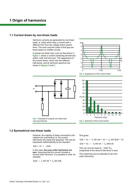
1 Origin of harmonics1.1 Current drawn by non-linear loadsHarmonic currents are generated by non-linearloads, ie. loads which draw a current with adifferent form from the voltage which powersthem. The most common loads of this type arethose based on rectifier circuits.A typical non-linear load, such as that shown infigure 1, draws a current containing all harmonicorders, both odd and even. The appearance ofthe current drawn, which has two differenthalf-waves, and its harmonic spectrum areshown in figures 2 and 3.(A)6420-2-4t(s)0 0.020.04Fig. 2: Appearance of the current drawn10090807060(%) 5040302010Fig. 1: Example of a typical non-linear load(non-symmetrical)01 3 5 7 9 11 13 15 17 19Harmonic orderFig. 3: Spectrum of the current drawn1.2 Symmetrical non-linear loadsHowever, the majority of loads connected to thenetwork are symmetrical, ie. the currenthalf-waves are equal and opposing. This can beexpressed mathematically by the equation:f( ωt + π) = − f( ωt)In this case, the even order harmonics arezero. Assuming that the current includes asecond order harmonic, it is possible to write, forexample:This gives:I( ωt + π) = I sin ( ωt + π) + I sin 2( ωt + π)1 2I( ωt + π) = − I sin ωt + I sin2 ωt1 2This can only be equal to − I( ωt ) if I 2(magnitude of the second harmonic) is zero.This reasoning can be extended to all evenorder harmonics.I( ωt) = I sin ωt + I sin 2ωt1 2Cahier Technique <strong>Schneider</strong> <strong>Electric</strong> no. 202 / p.4
1.3 3-phase loadsConsider a symmetrical, balanced, non-linear3-phase load without neutral connection, asshown in figure 4.Assuming that the currents drawn by this loadinclude the third harmonic, the third orderharmonic currents of each phase can be writtenas follows:i r3 = I 3 sin 3ωt⎛ 2π⎞i s3 = I3 sin 3 ⎜ωt− ⎟ = I sin ( 3 t − 2 ) = i⎝r33 ⎠ 3 ω π⎛ 4π⎞i t3 = I3 sin 3 ⎜ωt− ⎟ = I sin ( 3 t − 4 ) = i⎝r33 ⎠ 3 ω πir3 = i s3 = i t3The third order harmonic currents of all threephases are therefore equal.However, if there is no neutral conductor,ir + is + it = 0.The sum of the third order harmonic currents inparticular should be zero, which is only possibleif each of the components is zero.Symmetrical, balanced, 3-phase loads do nottherefore generate a third harmonic.This reasoning can be extended to all harmonicorders which are multiples of 3.Harmonic currents which are not zero aretherefore of the order 5, 7, 11, 13, etc, ie. theytake the form 6k ± 1.This can be demonstrated for any systemincorporating rectifiers, whether controlled ornot. We can therefore demonstrate thatharmonic orders are written h = (nxp) ± 1, wheren is an integer (1, 2, 3, 4, 5, etc) and p thenumber of rectifiers which make up the device.For example, a circuit which only includes onerectifier (half-wave rectification) has harmonicsof the order n ± 1 and presents all possibleharmonics, starting with 0 which is the directcurrent.For a bridge consisting of 4 diodes, the firstharmonic is of order 3, as demonstrated insection 1.2.Fig. 4: 3-phase loadirisitThis result is illustrated by the diagramconsisting of a diode rectifier with capacitivefiltering (see fig. 5), where the current drawn isrepresented by the curve in figure 6 and itsspectrum in figure 7.Fig. 5: 3-phase rectifier bridge with capacitive filtering3002001000-100-200-300Network voltage (V)Line current (A)0 0.020.04Fig. 6: Appearance of the current drawn by the circuitin figure 510090807060(%) 50403020100t(s)1 3 5 7 9 11 13 15 17 19 21 23 25Harmonic orderFig. 7: Harmonic spectrum of the current drawn by thecircuit in figure 5Cahier Technique <strong>Schneider</strong> <strong>Electric</strong> no. 202 / p.5