
Create successful ePaper yourself
Turn your PDF publications into a flip-book with our unique Google optimized e-Paper software.
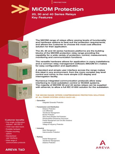
KEY FEATURESThe <strong>MiCOM</strong> range of relays fulfils the requirements at allvoltage levels from LV to EHV for Industrial, Distributionand Transmission Systems.COMMON FEATURES• 1A/5A dual rated CT's• Event and Disturbance Recording• Various casing and mounting options• Relays have rear RS 485 port with choice of protocolsand front RS 232 for local setting• A number of auxiliary supply and digital input voltageoptions> 20 Series Relays (Px2x)It will fulfil the basic requirements of industrial,transmission and distribution systems providing simplicityand ease of application in a wide range of installations.• Scalable solutions where type and quantity ofprotection features is model dependent• Flexible logic equations available on most models• Compact hardware options for easy installation• Common functions throughout the range• Multi-language HMI• Advanced protection functions on Phase 2 hardware> 30 Series Relays (Px3x)Designed to meet the rigorous requirements of MV, HVand EHV systems with particular focus on feeder andtransformer protection and control.• <strong>Protection</strong> with Bay level control options to facilitatefeeder management• Input/Output quantity selectable based onrequirements• A number of Rear Port hardware options available witha wide range of Protocols selectable via software• <strong>Protection</strong> functions available for unearthed/petersencoil earthed systems• Surface and flush mounted (incuding detachable HMIoption) as well as compact case models available inthe range• Full Programmable Scheme Logic and Function keys> 40 Series Relays (Px4x)It will fulfil the protection requirements for a wide marketof MV, HV, EHV and industrial systems and offers a widerange of protection functions.• Full Programmable Scheme logic available withGraphic Configuration Tool for easy setting• Scalable Input / Output hardware depending onrequirements• Operating voltage selectable via Software forOpto inputs• Hardware accessories available for easy mounting inracks or panels.APPLICATIONS> Px2x SeriesThe integrated functions reflect the different requirementsin system protection. The preferred applications are asfollows:• P12x: Universal Overcurrent protection for main orback-up protection on MV and HV systems• P22x: Motor <strong>Protection</strong> Series for LV and MV systems• P52x: Line Differential protection for MV and HVsystems with multiple communication options• P821 : Dedicated Breaker Failure <strong>Protection</strong> suitablefor EHV, HV and MV systems• P92x: Voltage and frequency protection suitable forgenerators, motors and feeders> Px3x Series30 Series protection devices provide a wide range ofprotection and control functions meeting stringent marketsegments. The range is especially suitable for petersencoil earthing requirements.The preferred applications are:• P13x: Feeder management relays andone box solution for MV and HV systems(including railway feeder)• P43x: Distance protection for MV, HV and EHVsystems and rail catenary requirements• P53x: Line differential protection for MV and HVsystems• P63x: Differential protection for transformers,generators and motors (including railwaytransformers).2>3
Px4x Series40 Series protection devices provide a wide range ofprotection and control functions and meets therequirements of a wide market segment.The preferred applications are:• P14x: Feeder management relay suitable for MV andHV systems• P24x: Rotating Machine Management relay forapplication on a wide range of synchronous andinduction machines• P34x: Generator protection for small to sophisticatedgenerator systems and interconnection protection• P44x: Full scheme Distance protection relays for MV,HV and EHV systems.• P54x: Line Differential protection relays for HV/EHVsystems with multiple communication options as wellphase comparison protection for use with PLC.• P74x: Numerical Busbar protection suitable forapplication on MV, HV and EHV busbars• P94x: Frequency protection for load shedding, loadrestoration and generator abnormal detectionCONTROL> Programmable scheme logicSimple logic equations as well as block logic is availablein a number of 20 series relays, see figure 1.Powerful graphical logic available in the 30 and 40 seriesrelays allows the user to customize the protection andcontrol functions of the relay. It is also used to programthe functionality of the opto-isolated inputs, relay outputs,LED and user alarms.The Programmable Scheme Logic can be used toimplement additional supervision features, such as tripcircuit supervision or implement complex logic such asfrequency restoration schemes. Schemes have beendeveloped capable of supervising the trip coil and circuitwith the circuit breaker open or closed.The Px40 gate logic includes OR, AND, NOT andmajority gate functions, with the ability to invert the inputsand outputs, and provide feedback. A number of generalpurpose logic timers are also available as well as thosetimers used to condition the relay contacts. The system isoptimized (event driven) to ensure that the protection outputsare not delayed by the PSL operation.The Programmable Scheme Logic is configured using thegraphical <strong>MiCOM</strong> S1 PC software, as shown in Figure 2The Px30 logic can be created using Boolean Equationsor a graphical interface as shown in figure 3.Figure 1> Independent <strong>Protection</strong> Settings GroupsUp to two setting groups are supported in the 20 Serieswhereas the 30 and 40 series can offer up to fourindependent setting groups. These can be activatedlocally, remotely or via a dedicated input and are used toallow for different system operating conditions and whereadaptive relaying is applied.> Measurement & Post Fault AnalysisFlexible logic for Px20The <strong>MiCOM</strong> Range of relays are capable of measuringand storing a wide range of system quantities such asCurrent, Voltage, Frequency, Power etc. depending on therelay functionality.All event, fault and disturbance records are time tagged toa resolution of 1ms using the internal real time clock andare stored in non-volatile memory. A supervised lithiumbattery ensures that the real time clock and records aremaintained during auxiliary supply interruptions.Where relays are communicating to a SCADA system,the protocols' telegrams can be used for external timesynchronization or alternatively an optional IRIG-B port isavailable for accurate time synchronization on all Px30and Px40 <strong>MiCOM</strong> relays.Some relays can also use an opto input to synchronizethe relay’s clock.Figure 2Programmable logic for Px40Figure 3Programmable logic for Px30
Power System MeasurementA comprehensive set of measurement values includinginstantaneous and derived values are available on therelays.These measured values can be displayed on the frontLCD display or transferred locally or remotely as per theuser requirements.POST FAULT ANALYSIS> Event recordsThese are generated for status changes to logic inputsand outputs, modifications to one or more settingparameters and alarm signals.All events are time-tagged and stored in chronologicalorder in a cyclic memory where the oldest record isoverwritten once the relay's maximum event count isexceeded. These are readily available for viewing on theLCD, or extraction via the communication ports.> Fault recordsAt least 5 records are supported on all relays and forevery fault, the following information is captured in therelay records• A fault number• The date and time• The active setting group• The function that issued the trip• The magnitude of the current/voltage that gave rise tothe trip command> Disturbance recordsThe internal disturbance recorder will record the sampledvalues of all analog input variables such as phasecurrents and voltages etc. where applicable during a fault.Oscillographic analysis can be performed usingMICOM S1 which will provide the means to quicklyanalyse analog and digital signals on the same time-scalefor convenience. Disturbance records can be extractedfrom the relay via the communication ports and saved inthe COMTRADE format.Figure 4Oscillography analysis using <strong>MiCOM</strong> S1 Softwarefor Optimum resultsRELAY COMMUNICATIONSAs standard, a front communication port is available forlocal access to the relay. An auxiliary rear communicationport is available as an option on relays providing anengineering port for easy access to settings, records andmeasurements for protection engineers. A main rearcommunications port is also available for interface to aSCADA system. A number of protocols are available asan option for this purpose.(See cortec code for each relay)Figure 5A typical substation control systemSCADAInterfaceMaster Clock(GPS)IRIG-BportModem(remote access)SCADA InterfacePx40EAI232(local access)Px30Px20Px20Mx20Px304>5
Local CommunicationThe front EIA(RS)232 communication port has beendesigned for use with the <strong>MiCOM</strong> S1 software and isprimarily for configuring the relay settings andprogrammable scheme logic. It is also used to locallyextract event, fault and disturbance record informationand can be used as a commissioning tool by viewing allrelay measurements simultaneously. In Px20 / Px30 thefront EIA(RS)232 is also used to upgrade relay software.In Px40 a separate front parallel port is used for this.215> Rear CommunicationThe rear communication port is based upon EIA(RS)485voltage levels and is designed for permanent multidropconnection to network control and data acquisitionsystems. An optional fiber optic communications port isalso supported on the 30 and 40 platforms.34In general, the following protocols are available atordering or via setting selection on the relays.• Courier/K-Bus• Modbus• IEC 60870-5-103• DNP3.0The following protocol is only available on Px30 / Px40relay models with an Ethernet port currently.• IEC61850Fig 5 illustrates the flexibility with which the MICOM rangeof relays can be integrated into a SCADA system as wellas provide engineering data for remote access by utilityengineers.USER INTERFACESThe user interface and menu text are available in English,French, German and Spanish as standard.Other languages such as for example Russian and Italianare supported on some relays depending on marketrequirements.The ability to customize the menu text and alarmdescriptions are also supported on Px30 and Px40.Figure 66Px40 series user interface110Figure 7Compact case user interfaceThe front panel user interfaces, as shown inFigures 6, 7 & 8 comprise:(1) A back-lit liquid crystal display (20, 30, 40 series)Graphic LCD display (30 series only)(2) Four fixed function LEDs (20, 40 series)Five fixed function LEDs (30 series)(3) Up to Four user programmable LEDs (20 series)Up to Eight user programmable LEDs (40 series)Twelve user programmable LEDs (30 series)(4) Menu navigation and data entry keys.(5) "READ" and "CLEAR" keys for viewing and reset ofalarms(6) An upper cover identifying the product name, whichmay be raised to view full product model number,serial number and rating information.(7) A lower cover concealing the front EIA(RS)232 port,download/monitor port and battery compartment.Cover not available on compact case.(8) Facility for fitting a security seal(9) Bay control keys up to 6 bays control (30 series)(10) Programmable Function keys(compact range and 30 series)3Figure 8Px30 series user interfacewith bay control2561542784User Language optionsthat provide true globalconvenience3789
GP439TRIPALARMOUT OF SERVICEHEALTHYEDIT MODEGSELF MONITORINGComprehensive Self monitoring procedures within thedevice ensure that internal hardware and software errorsare detected thus ensuring a high degree of reliability.Automatic tests are performed during start-up and a cyclicself monitoring tests are performed during operation. Anydeviations are stored in non-volatile memory and theresult of the fault diagnosis determines whether a blockingof the device will occur or whether an alarm is only issued.MECHANICAL DESCRIPTION> CasesThe <strong>MiCOM</strong> series relays are housed in a speciallydesigned case providing a high density of functionalitywithin the product. Communication ports and model/serialnumber information is concealed by upper and lowercovers.Px4x / Px2xPx2xC / Px3xCPhysical protection of the front panel user interface andprevention of casual access is provided by an optionaltransparent front cover, which can be fitted or omittedaccording to choice, since the front panel has beendesigned to IP52 protection against dust and waterThe cases are suitable for either rack or panel mountingas shown in Fig.9.An option for surface mounting is also supported on the30 series range and a compact case option is availableon a few 20 and 30 series relays for installations withspace limitations.Taking into account the differing case widths -relays canbe combined with or without the use of standard blankingplates to form a complete 19" mounting. This saves spaceand allows for a neat installation.> WiringExternal connections are made via ring type terminal onall <strong>MiCOM</strong> relay except on the compact case. These takepin type terminals along with the 30 series relays as anoption.Px2xC / Px3xCPx2x / Px3x / Px4xFRONT VIEWCBPx3xAAACX6FF1F2F3F4GSIDE VIEWCDEA (including brackets)EGBBDFigure 9Typical case dimensionsTypicalcase dimensions Table A B C D E F GPx201)Px3020TE30TE40TE40TE rack84TE84TE rack40TEsurface84TEsurface40TE177184.5103155213.4260.2434.8481.6260.2481.6206240(inc. wiring)139,8223227.9270(inc. wiring)166,4249,6157.5155.2156253.6 177.5257.1 177.5Px4060TE80TE177309.6 240270413.2(inc. wiring) (inc. wiring)157.5 max80TE rack483Px20C/Px30CcompactCompactincl. brack.294.4310175.6 88.5 253 162.5 294.4Note: Maximum sizes for guidance only, for specific product information please check the relevant productdocumentation. (All dimensions in mm)6>71)In addition 24TE case variant available for P132
TECHNICAL DATA> Power suppliesA wide range of power supply options are available at theordering stage.Nominal Voltage Operate Range (V)Vnom. DC ACPx20 24- 60 Vdc 19.2-76 Vdc -Ph 2 48-250 Vdc 38.4-300 Vdc 38.4-264 Vac48-240 VacPx20 24- 60 DC 19.2-72 -Ph 1 48-150 DC 38.4-180 -130-250 DC 104-300 DC -100- 250 AC - 80-275125-250 DC 100-300 DC -100- 250 AC - 80-275 ACPx30 24 DC 19-29 -48-250 DC 38-300 100-230Px40 24-48 DC 19-65 -48-125 DC 37-150 24-110110-250 87-300 80-265> Digital InputsA wide range of opto input voltages are supportedthroughout the rangePx20Ph 2Px20Ph 1Px30Px40Auxiliary Voltage24- 250 Vdc24- 240 Vac24-60 DC48-150 DC130-250 DC/100-250 AC125-250 DC/100-250 AC48-150 DC130-250 DCDigital Operating range (V)19.2 - 300 Vdc19.2 - 264 Vac15.2-60 DC25.6-180 DC38.4-300 DC/38.4-275 AC84-174 DC25.6-180 (AC immune)38.4-300 (AC immune)ThresholdsStandard Variant> 18 (Uaux. 24-250V DC)Further Options> 73V (67% of Uaux. 110V DC)> 90V (60-70% of Uaux. 125/150V DC)> 146V (67% of Uaux. 220V DC)> 155V (60-70% of Uaux. 220/250V DC)Vmin/Vmaxthresholds24/27, 30/34, 48/54,110/125 and 220/250(software selectable)General Series DataFrequency 50/60HzDual rated 1A/5ACT thermal ratings continuous: 4Inomfor 10s: 30 Inomfor 1s: 100 InomOpto InputsOutput ContactsCarry: continuousMake and carryLED Indication(freely programmable)Function Keys / Hot KeysSettings GroupsFault RecordsEvent RecordsDisturbance RecordsProgrammable logicIRIG BLCD DisplayFront Port (RS 232)Rear PortCourierModbusIEC 60870-5-103IEC 60870-5-101DNP3.0IEC 61850One Box Bay Controlwith MimicTerminalsPx20 Px20C Px30 Px30C Px40X X X X XX X X X XX X X X Xmax 8 max 7 max. 34 max 2 max. 24max 9. max 8 max 46 max 8 max. 465A 5A 5A 5A 10A30A for 3s 30A for 3s 30A for 0.5s 30A for 0.5s 30A for 3s8 (4) 8 (4)No 423/18(for products with text display)6(for products with text display)17 (12) 12 (8)410 functions/2 hotkeys(available on somemodels)1/2 2 4 4 4 (2)5/25* 5 8 8 575/250* 75 200 100 250-5125 (15s max) 8 (24s max) 8 (16.4 s max) 8 (16.4 s max) 75 s max.Flexible logic(available on some models)Simple 'AND' logic Fully programmable Fully programmable Fully programmableNo No Option Option OptionAlphanumeric AlphanumericAlphanumeric /Graphical (some models AlphanumericAlphanumericonly)Yes(most models)Yes Yes Yes YesYesYesYes, 2nd rear port option Yes, 2nd rear port option Yes, 2nd rear port optionEIA(RS)485 (availableNoEIA(RS)485 or fiber EIA(RS)485 or fiberK-Bus/ EIA(RS) 485 oron some models)fiber (some models only)EIA(RS)485 EIA(RS)485/Glass fiber EIA(RS)485 or fiber EIA(RS)485 or fiber EIA(RS) 485 or fiber(some models only)EIA(RS)485 EIA(RS)485/Glass fiber EIA(RS)485 or fiber EIA(RS)485 or fiber EIA(RS) 485 or fiber(some models only)No No EIA(RS)485 or fiber EIA(RS)485 or fiber NoEIA(RS)485 (availableon some models)No EIA(RS)485 or fiber EIA(RS)485 or fiber EIA(RS) 485 or fiber(some models only)NoNoAvailable on somemodelsNoAvailable on somemodelsNo No YesNo No(available on some models)Ring Pin Pin or Ring Type Pin Ring*Available on <strong>MiCOM</strong> Phase 2 for P120,P122,P123,P125,P126,P127.
<strong>MiCOM</strong> Series DataOVERCURRENT AND FEEDER MANAGEMENT RELAYSCT InputsVT inputsOpto Inputs ( max)1DeviceP120 P121 P122 P122C P123P124SelfP124DualPower PowerP125 P126 P127 P130C P132 P138RailP139 P141 P142 P143 P1441 4 4 4 4 4 4 1 4 4 4 4 2 4 5 5 5- - - - - - - 1 1 3 3 4/5 1 4/5 3 3 3/42 2 3 7 5 - 5 4 7 7 2 40 16 40 8 16 325 54 2 3/416P14532Output Contacts (max)15 5 7 8 9 2 7 7 9 9 8 32 24 32 7 15 301532Output for Striker TriggeringMagnetic FlagsRTDs (max. option)Analogue I/O (max. option)Function Keys/HotkeysBay Control & Monitoring- with MimicInterlocking Logic<strong>Protection</strong>1 Phase or Earth overcurrent3 Phase overcurrentGround faultPhase directionalGround Fault directionalSensitive directional earthfaultTransient Ground FaultdirectionalWattmetric earthfaultNeutral admittanceRestricted earthfaultVoltage controlled overcurrentNegative sequence overcurrentThermal overloadUndercurrentOver/Under voltageResidual over voltageNegative sequence overvoltageOver/Under frequencyRate of change of frequencyIncomplete sequence relayMaster sequence deviceLock-outDirectional PowerCircuit breaker failureMotorStartup MonitoringAutorecloseCheck synchronisingBroken conductorVoltage transformer supervisionCurrent transformer supervisionCold load pick-upInrush blockingSwitch on to faultCircuit breaker monitoringTrip Circuit SupervisionLimit value monitoringProtective SignallingInterMicom50/51P/N50/51P50/51N67P67N67N67N67WYN6451V46493727/5959N4781O/U87R4834863250BF49LR66792546BCVTSCTSSOTFTCS85- - - - - 1 1 - - - - -- - - - -- - - - - X X - - - - - - - - - -- - - - - - - - - - - 10 1 10 - - -- - - - - - - - - - - 1/2 1/2 1/2 - - -- - - X - - - - - - X X - X X X X- - - - - - - - - - - X - X - - -- - - - - - - - - - - - - X - - -- - - - - - - - - - - X - X X X XX - -- X X- X X- - -- - -- - ----X-----------X---------------- - - - X - - - - X -X X X X - X X X X - XX X X X X X X X X X X- - - - - - X X X X X- - - - X X X X X X X- - - - - - - - - - -- - - - - - - - - - X- - -X X XX X XX X XX X XX X X- X - - -- - - - - - X X X X X - X X X X- - - - - - - - - - X X X X X XX X - X - - X X X - - - - X X X- - - - - - - - X - - - - X X X- X X X - X - X X X X - X X X X- X X X X X - X X X X X X X X X- X X X - - X X X X - X X X X- - - - - - - - X X X X X X X X- - - - - - X X X X X - X X X X- - - - - - - - - X X - X X X X- - - - - - - - X X X X X X X X- - - - - - - - - X X - X X X X- - - - - - - - - X X - X - - -- - - - - - - - - - - - X - - -X X X X X X X X X X X X X X X X- - - - - - - - X X X - X - - -- X X X - X - X X X X X X X X X- - - - - - - - - X X - X - - -- - - - - - - - - X X - X - - -- - - X - X - X X X X - X - X X- - - - - - - - - - X - X - - X- X X X - X - X X - - - - X X X- - - - - - - - - X X X - X X X X X X- - - - - - - - - - X X - X X X X X X- X X X - X - X X X X - X X X X- X - X - - - - X X X - X - - -- - - X - - - X X X X - X X X X- X X X - X - X X - X - X X X X- X X X - X - X X - X - X X X X- - - - - - - - - X X X X - - -- - - - - - - - - X X - X - - -- - - - - - - - - X X - X - - -1. Please note that some relays may have a limit on max. I/O when used as a combination.2. 3V0 measured input and allows vee connected VTs.----X--X-XXXXX-XXXXXXXXXXXX--X-X--X-XX-XXX-------X--X-XXXXX-XXXXXXXXXXXX--X-X--XXXX-XXX---8>9
MOTOR AND GENERATOR MANAGEMENT RELAYSCT InputsVT inputsOpto Inputs (max) 1Device P220 P225 P226C P241 P242 P243 P341 P342 P343 P3444 4 4 4 4 7 4 5 8 8- 1 1 3 3 3 4 4 4 55 6 7 8 16 16 16 24 32 32P3459632Output Contacts (max) 16 6 8 7 16 16 15 24323232RTDs/thermistors (option)Analogue I/O (option)Function Keys/HotkeysInterlocking Logic<strong>Protection</strong>Motor <strong>Protection</strong>- Short circuit 50/51- Motor Differential 87M- Locked Rotor 50S/51LR/51S- Reverse Power 32R- Reacceleration 27LV- Startup Monitoring/Excessive long start 66/48/51- Negative sequence overvoltage 47- Out of Step 55- Loss of load 37- Undercurrent 37P/37N- Unbalance/Lock-out 30/46/86- Speed switch inputs14- Anti BackspinGenerator <strong>Protection</strong>- Generator Differential 87G- Interturn/split phase 50DT- Underimpedance 21- Pole Slipping 78- Directional Power 32L/O/R- Loss of Field 40- Restricted earthfault 64- 100% Stator earth fault (3rd harmonic) 27TN- 100% Stator Earth Fault (Low Freq. Injection) 64S- Overfluxing 24- Unintentional energisation at standstill 50/27- Voltage dependent O/C- Rotor Earth Fault51V64RAncillary FunctionsPhase overcurrent 50/51PPhase directional67PGround fault50N/51NGround Fault directional67NSensitive directional earthfault67NWattmetric earthfault64N/32NNegative sequence overcurrent460CNegative sequence thermal46TThermal overload 38/49Under/Over voltage 27/59Residual over voltage59NNegative sequence overvoltage 47Under frequency81UOver frequency81OTurbine abnormal frequency81ABVoltage vector shiftdVθRate of change of frequency81RCircuit breaker failure50BFCircuit breaker monitoringTrip Circuit SupervisionTCS6/0 or 4/2 10/3 - 10/0 10/0 10/0 - 10/00/1 0/2 - 4/4 4/4 4/4 4/4 4/4- - X X X X X X- - - X X X X XX-X-XX--XXXX-----------X-X-----X------X X X X X- - - - X - -X X X X X - -- - X X X - -X X X X X - -X X X X X - -- - X X X - -- - X X X - -X X X X X - -X X X X X - -X X X X X - -X X X X XX X X X X- - - - - - -- - - - - - -- - - - - - X- - - - - - -- - - - - X X- - X X X - X- - - - - X X- - - - - - -- - - - - - X- - - - - - X- - - - - - XX X X X X X X- - - - - X XX X X X X X X- - - - - X -- - X X X - X- - X X X X XX X X X X - X---X--XX--XX--XX--XX--XXXXXX--XXX X X X X X X X10/04/4XXXXXXXXXXXXXXXXX-XXXXXXXX--XXX10/04/4XX- -- -- -- -- -- -- -- -- -- -- - - - - - X X XX X X X X X XX X X X X X X- - X X X X X- - - - - X X X X- - X X X X X- - - - - X X- - - - - - X X XXXXXXXXXXXXXXXXX-XXXXXXXX--XXX10/04/4XX----------XXXXXXXXXXXXXXXX-XXXXXXXXXXX--XXX1. Please note that some relays may have a limit on max. I/O when used as a combination.
DISTANCE RELAYS AND PHASOR MEASUREMENT UNITDevice P430C P432 P433 P435 P436RailP437P438RailP439 P441 P442 P443P444 P445 P847CT Inputs44/5442 4/5 34 4 4 44412VT inputs34/54/54/51 4/5 24/5 4 4 44412Opto Inputs(max) 1252203228 32 2840 8 16 24242432Output Contacts(max) 1838304646 46 4626 14 21 324632 32RTDs (option)-1111 1 11 - - ----Analogue I/O (option)-1/21/21/21/2 1/2 1/21/2 - - ---XFunction Key/HotkeysX - X X - X -- X X XXXXBay Control & Monitoring with Mimic-X--- - -X - - ----Interlocking LogicXX--- - -X- - -- --<strong>Protection</strong>Distance <strong>Protection</strong>- Distance 21/21N3 pole- Autoreclose 791/3 pole- Power Swing Blocking 78- Out of step tripping 68- Check synchronising 25- Directional Power 32- Switch on-to fault 50/27- Mutual Compensation- Rail Catenary <strong>Protection</strong> HZ- Defrost <strong>Protection</strong>- Train startups di/dt,dv/dt,dΦ/dtPhasor MeasurementPMUAncillary FunctionsPhase overcurrent 50/51PPhase directional67PDelta directional comparison∆I/∆VGround fault 50/51NGround Fault directional67NTransient Ground Fault directional 67NNeutral admittanceYNWattmetric earthfault67WNegative sequence overcurrent 46Directional negative sequence 46/67Thermal overload 49Under/Over voltage 27/59Residual over voltage59NOver/Under frequency81URate of change of frequency81RCircuit breaker failure50BFBroken Conductor46BCStub Bus <strong>Protection</strong>50STXX-XX-XX----XX-XX- -X - X XX - X X - - - X - - - -XXXXXXXXX-XXXXX-XXX-XXXX----X-XXXX----XX-XXXX-X-X-XX-X-XX-X-XX-XX---X X X - X - X X X X X XX X X - X - X - - - - -X X X X X X X X X X X XX - - - X - - X X X X -- - - 16 2/3 - 25/50/60 - - - - - -- - - - - X - - - - - -- - - X - X - - - - - -- - - - - - - - - - - - -XX-XX-XX-X--XX-XX-XX-XX-XX-XXXXX-XX-XXXXXX--XX--XXXXXXXXXXXXX X - - - X - - - - -- - - X - - - - -XXXXXXXXXXXXXXXXXXXXXXXX--XX---XXXXXXXXX--XX---XXXXXXXXXXXXX---XXXXX---XXXXXX--XXX-X---X- - X X - X - X X X X XX X X X X X - X X X X X-XXXXX--XXX------------XXX-XX---XXXXXXXXXXVoltage/Current transformersupervisionVTS/CTSXXXXX X XX X X XXXXCapacitive voltage transformersupervisionCVTSChannel Aided Scheme Logic 85-X-X-X-X- - -- X -- X X - X -X X X X X X--Trip Circuit SupervisionTCSXXXXX X XX X X XXXXInterMicomX-XXX X -X - X XXX-1. Please note that some relays may have a limit on max. I/O when used as a combination.10>11
VOLTAGE, FREQUENCY AND ANCILLARYPROTECTION RELAYSAREVA Track Record -<strong>MiCOM</strong> Series RelaysDeviceCT InputsVT inputsOpto Inputs(max)Output Contacts(max)<strong>Protection</strong>Breaker Failure <strong>Protection</strong>50BF- 2 Stage- Pole Discrepancy- Dead Zone FunctionAutoreclose 79- Mesh Corner/Single Switch- Check Sync 25- Ferroresonance SuppressionOpen Line DetectorDLO- High Speed Breaker Fail 50BF- Fast Hybrid Output contacts- 3 pole trippingVoltage and Frequency <strong>Protection</strong>- Undervoltage 27- Overvoltage 59- Residual Overvoltage 59N- Phase Sequence Voltage 47/27D- Under/Over frequency 81U/O- Rate of change of81RFrequency (df/dt+t)- Frequency supervised Rate of change of Frequency(f+df/dt)- Frequency supervised averageRate of change of Frequency(f+∆f/∆t)81RF81RAV- Generator Abnormal Frequency 81AB- Load Restoration logic- Trip Circuit Supervision TCSADDITIONAL INFORMATION RESOURCEFor further information on the <strong>MiCOM</strong> series of relays may beobtained from www.areva-td.comAREVA T&D Worldwide Contact Centre:http://www.areva-td.com/contactcentre/Tel.: +44 (0) 1785 250 070www.areva-td.comwww.areva-td.com/protectionrelaysP821 P842 P846 P921 P922 P923 P941 P9434 - 6 - - - - -- 4 3 4 4 4 3 35 48 16 2 5 5 16 329 32 24 4 8 8 15 30X - - - - - - -X - - - - - - -X - - - - - - -X - - - - - - -- X - - - - - -- X - - - - - -- X - - - - - -- X - - - - - -- - X - - - - -- - X - - - - -- - X - - - - -- - X - - - - -- - - X X X X X- - - X X X X X- - - X X X - -- - - - X X - -- - - - X X X X- - - - - X X Xyes- - - - - by X Xlogic- - - - - - X X- - - - - - X X- - - - - - X XX X X - X X X XOur policy is one of continuous development. Accordinglythe design of our products may change at any time. Whilstevery effort is made to produce up to date literature, thisbrochure should only be regarded as a guide and isintended for information purposes only. Its contents do notconstitute an offer for sale or advise on the application ofany product referred to in it. We cannot be held responsiblefor any reliance on any decisions taken on its contentswithout specific advice.>> P12x <strong>MiCOM</strong> series introduced in 1998.Worldwide application, with over150 000 units delivered>> P13x <strong>MiCOM</strong> series introduced in 2001.Worldwide application, with over3200 units delivered>> P14x <strong>MiCOM</strong> series introduced in 1999.Worldwide application, with over11 000 units delivered>> P22x <strong>MiCOM</strong> series introduced in 1999Worldwide application, with over7 000 units delivered>> P24x <strong>MiCOM</strong> series introduced in 1999Worldwide application, with over1 500 units delivered>> P34x <strong>MiCOM</strong> series introduced in 1999.Worldwide application, with over2 300 units delivered>> P43x <strong>MiCOM</strong> series introduced in 2001Worldwide application, with over4 600 units delivered>> P44x <strong>MiCOM</strong> series introduced in 1999.Worldwide application, with over6 000 units delivered>> P52x <strong>MiCOM</strong> series introduced in 2003Worldwide application, with over500 units delivered>> P54x <strong>MiCOM</strong> series introduced in 1999Worldwide application, with over3 500 units delivered>> P63x <strong>MiCOM</strong> series introduced in 2001Worldwide application, with over4 500 units delivered>> P74x <strong>MiCOM</strong> series introduced in 2002Worldwide application, with over250 units delivered>> P92x <strong>MiCOM</strong> series introduced in 2000Worldwide application, with over18 000 units delivered>> P94x <strong>MiCOM</strong> series introduced in 1999Worldwide application, with over12 000 units deliveredAUTOMATION-L3-PROTRANGE-BR-11.08-1827-EN - © - AREVA - 2008. AREVA, the AREVA logo and any alternative version thereof are trademarks and service marks of AREVA. <strong>MiCOM</strong> is a registeredtrademark of AREVA. All trade names or trademarks mentioned herein whether registered or not, are the property of their owners. - 389191982 RCS PARIS - Printed in France - SONOVISION-ITEP