
You also want an ePaper? Increase the reach of your titles
YUMPU automatically turns print PDFs into web optimized ePapers that Google loves.
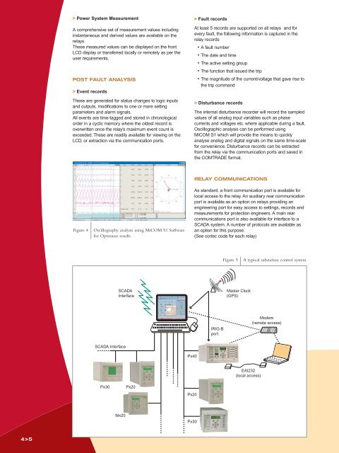
Power System MeasurementA comprehensive set of measurement values includinginstantaneous and derived values are available on therelays.These measured values can be displayed on the frontLCD display or transferred locally or remotely as per theuser requirements.POST FAULT ANALYSIS> Event recordsThese are generated for status changes to logic inputsand outputs, modifications to one or more settingparameters and alarm signals.All events are time-tagged and stored in chronologicalorder in a cyclic memory where the oldest record isoverwritten once the relay's maximum event count isexceeded. These are readily available for viewing on theLCD, or extraction via the communication ports.> Fault recordsAt least 5 records are supported on all relays and forevery fault, the following information is captured in therelay records• A fault number• The date and time• The active setting group• The function that issued the trip• The magnitude of the current/voltage that gave rise tothe trip command> Disturbance recordsThe internal disturbance recorder will record the sampledvalues of all analog input variables such as phasecurrents and voltages etc. where applicable during a fault.Oscillographic analysis can be performed usingMICOM S1 which will provide the means to quicklyanalyse analog and digital signals on the same time-scalefor convenience. Disturbance records can be extractedfrom the relay via the communication ports and saved inthe COMTRADE format.Figure 4Oscillography analysis using <strong>MiCOM</strong> S1 Softwarefor Optimum resultsRELAY COMMUNICATIONSAs standard, a front communication port is available forlocal access to the relay. An auxiliary rear communicationport is available as an option on relays providing anengineering port for easy access to settings, records andmeasurements for protection engineers. A main rearcommunications port is also available for interface to aSCADA system. A number of protocols are available asan option for this purpose.(See cortec code for each relay)Figure 5A typical substation control systemSCADAInterfaceMaster Clock(GPS)IRIG-BportModem(remote access)SCADA InterfacePx40EAI232(local access)Px30Px20Px20Mx20Px304>5