MicroMaster 6SE92 - ECT Sales & Service
MicroMaster 6SE92 - ECT Sales & Service
MicroMaster 6SE92 - ECT Sales & Service

You also want an ePaper? Increase the reach of your titles
YUMPU automatically turns print PDFs into web optimized ePapers that Google loves.
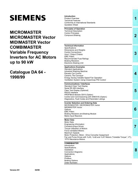
MICROMASTERMICROMASTER VectorMIDIMASTER VectorCOMBIMASTERVariable FrequencyInverters for AC Motorsup to 90 kWCatalogue DA 64 -1998/99IntroductionProduct OverviewTechnical FeaturesConformity to International StandardsQuotation SheetPrinciples of OperationTechnical DescriptionControl PrinciplesCompound BrakingTechnical InformationSpecificationsDimensions and WeightsControl ConnectionsInput / Output ChokesEMC FiltersRecommended Fuse RatingsBraking ResistorsElectronic Braking UnitApplications ExamplesStandard ApplicationsIndustrial Washing MachineElevator Car ControlCeramic Tile ConveyorEnergy Saving Variable Speed Fan OperationVentilation System Using Closed-loop PID ControlCommunications / InterfacesStandard Clear Text DisplaySerial RS 485 InterfaceClear Text Display (Optional)RS232 InterfacePROFIBUS Module CB15 (Option)Control and Commissioning with SIMOVIS (Option)Diagnostics, Fault Codes and Parameter ListingsInverter Selection and Ordering DataMICROMASTER / MICROMASTER VectorMIDIMASTER VectorOptionsEMC FiltersBraking Resistors and Braking ModuleMains Input ReactorsMotor DataMotor DataEngineering InformationConstant-torque DrivesTorque Utilisation of MotorsForce-ventilated MotorsMaximum SpeedsMotor Protection, Motor - Drive Converter AssignmentFan and Pump Drives with 1LA5, 1LA6 and 1LA7 Motors (“Variable Torque”, VT),1FP5 Reluctance MotorsCOMBIMASTERIntroductionSpecificationsInstallationConnection DiagramsApplicationsOptionsProfibusBraking OptionsOrder Numbers12345678Version B1 04/99
MICROMASTERMICROMASTER VectorMIDIMASTER VectorIntroduction1. Introduction 1/11.1 Product Overview 1/11.2 Technical Features 1/21.3 Conformity to International Standards 1/31.3.1 CE Mark 1/31.3.2 Electromagnetic Compatibility 1/3Quotation Sheet 1/4
MICROMASTERMICROMASTER VectorMIDIMASTER VectorIntroduction1. INTRODUCTIONThe MICROMASTER, MICROMASTER Vector, andMIDIMASTER Vector family of standard drives from Siemensuses the latest IGBT power technology and are the result ofmany years of experience in the field of inverter technology.A fully compatible range is offered from 120W to 75kW, or upto 90kW for applications with a quadratic speed/torquecharacteristic, with high performance Sensorless VectorControl as standard. This offers the user the benefits of hightorque and dynamic performance across a broad spectrum ofapplications.A parallel range of non-vector drives, the MICROMASTER,from 120W to 7.5kW is ideal for embedded control of low endmachines.For the ultimate in variable speed drive packaging, theCOMBIMASTER is on offer (see Section 8), combining motorand inverter in one compact unit.Ease of use, an excellent price/performance ratio andcompact size are guaranteed, along with conformance to thehighest quality and reliability standards in the world.1.1 Product OverviewThe MICROMASTER, MICROMASTER Vector andMIDIMASTER Vector are intended for use anywhere in theworld and therefore support a wide range of mains voltages:- An RS485 serial interface is standard, allowing up to 31drives to be networked to a PLC or PC.- The drive may be enabled via the keypad, via digitalinputs or over the standard RS485 serial interface.- The motor speed setpoint can be selected, using a digitalsetpoint, motorised potentiometer, fixed frequency,analogue input or via the serial link.- Mixed mode control is also available, allowing drivecontrol and setpoint input to be from different sources.- A DC injection brake is incorporated, allowing DC to beoutput even when the motor is stationary.- The drives can be configured to start automaticallyfollowing a mains break or after a fault.- The parameter sets are fully compatible between thedifferent product types, reducing the learning time.- All drives are certified in accordance with VDE, UL andCanadian UL, and are manufactured to ISO9001.- All drives conform to the requirements of the EC lowvoltage directive 73/23/EEC and have been awarded theCE mark.- All drives are guaranteed Y2K (year 2000) compliant.1/3 phase 208-240V±15%3 phase 380 - 500V±10%3 phase 525 - 575V±15% (MIDIMASTERVector only)Two levels of operational characteristics are offered:- MICROMASTER Vector/MIDIMASTER Vector offer highperformance Sensorless Vector Control for high torque atlow speeds and excellent dynamic performance. Thisallows use of the drive even in demanding applicationssuch as lifts, hoists and industrial washing machines.- MICROMASTER offers standard open loop V/F Controland is ideal for simple applications such as pumps andfans.- Both ranges of drives benefit from the standard inclusionof a PID controller (PI for the MICROMASTER) for closedloop process control.- All the products make use of the same, simple to use,standard user interface consisting of seven push buttonsand LED display.- User-friendly screwless terminals are used for the controlconnections.Siemens DA 64 – 1998/99 (04/99) 1/1
IntroductionMICROMASTERMICROMASTER VectorMIDIMASTER Vector1.2 Technical FeaturesDRIVE MICROMASTER MICROMASTERVectorMains VoltagePower Ranges1 AC 230V3 AC 230V3 AC 380-500V3 AC 525-575V1 AC 208 V-240 V±10%3 AC 208 V-240 V±10%3 AC 380 V - 500 V±10%120 W - 3.0 kW120 W - 4.0 kW370 W - 7.5 kWMIDIMASTER Vector3 AC 208 V - 240 V±10%3 AC 380 V - 500 V±10%3 AC 525 V - 575 V±15%5.5 (VT 7.5)kW – 45 (VT 45)kW11 (VT 15)kW – 75 (VT 90)kW2.2 (VT 4)kW – 37 (VT 45)kWProtection Level IP20/NEMA1 IP21/NEMA1 or IP56Conformance to55011 A EMC1 AC 230V3 AV 230V3 AC 380-500V3 AC 525-575VConformance to55011 B EMC1 AC 230V3 AV 230V3 AC 380-500V3 AC 525-575VIntegrated FilterFootprint FilterFootprint FilterFootprint FilterFootprint FilterFootprint FilterFootprint FilterFootprint FilterIntegrated FilterIntegrated FilterIntegrated FilterIntegrated FilterExternal FilterExternal FilterExternal FilterExternal FilterTemperature Range 0 – 50 o C 0 – 40 o CControl Method V/F Sensorless Vector, FCC, V/FOverload Capability 1 )50% for 60 sec1.5 x rated outputcurrent for 60 sec1.5 x rated output current for 60 sec2 x rated output current for 3 secProtection FeaturesUndervoltage, Overvoltage, Overload, Short-circuit, Earth Fault, Motor Pull-out, Motor Overtemperature,Drive OvertemperatureMaximum MotorCable Lengthsee Section 3 see Section 3Frequency Range 0 – 400 Hz 0 – 650 Hz 0-650 HzSetpoint ResolutionDigital Inputs3 configurable(19 functions)0.01 Hz6 configurable (24 functions)Fixed Frequencies 7 8Ramp Times 2Relay Outputs1 configurable110 V AC / 0.3 A30 V DC / 1.0 A2 configurable240 V AC / 0.8 A30 V DC / 2 AAnalogue Inputs 1 2Analogue Outputs - 1 configurable 2 configurableSerial InterfaceRS485Braking Compound Braking Braking Chopper External Braking ModuleProcess Control PI PID1 ) The overload capability relates to the rated output current of the drives (MICROMASTER and MICROMASTER Vector) and to therated output currents for operation with constant torque (CT, MIDIMASTER Vector).Duty cycle duration must be at least 5 mins.Table 1:Technical Features1/2 Siemens DA 64 – 1998/99 (04/99)
MICROMASTERMICROMASTER VectorMIDIMASTER VectorIntroduction1.3 Conformity to International Standards1.3.1 CE Mark:The MICROMASTER, MICROMASTER Vector andMIDIMASTER Vector frequency inverters comply with therequirements of the Low Voltage Directive, 73/23/EEC. The CEMark on the units demonstrates this conformity. A declaration ofconformity can be issued. The units are certified to comply withthe following standards:EN60204-1EN60146-1-1Safety of Machinery, ElectricalEquipment or MachinesGeneral Requirements forSemiconductor converters and linecommutated converters1.3.2 Electromagnetic Compatibility:The MICROMASTER, MICROMASTER Vector andMIDIMASTER Vector frequency inverters will, when correctlyinstalled and put to their intended use, satisfy therequirements of the Directive 89/336/EEC concerningElectromagnetic Compatibility. If the guidelines on installationto reduce the effects of EMI are followed, the relevantrequirements for CE certification of the machine will be met.The table below lists the measured results for emissions ofand immunity to interference for MICROMASTER,MICROMASTER Vector and MIDIMASTER Vector inverters.The inverters were installed according to the guidelines withshielded motor cables, shielded control cables and optionalmains filters (except for the single phase units):Test Measurement Tested Value Required limit forEN50081/EN50082RFI Emissions EN55011 and Conducted via Mains cable and 1/3 AC 230/400/460V with integral Class AEN55022radiated through airfilter>= Class A1/3 AC with external filter >= Class B Class B(leads - related emissions only)ESD ImmunityEN61000-4-2ESD through airESD through direct contactLevel 4: 15 kVLevel 4: 8 kV8 kV4 kVElectric Field ImmunityEN61000-4-3Electric Field applied to unit 10 V/m 26-1000 MHz 10 V/mBurst Interference ImmunityEN61000-4-4Applied to all cable terminations:Mains LeadsMotor LeadsControl LeadsBraking Resistor/Module LeadsDC Link LeadsLevel 4: 4 kVLevel 4: 4 kV4 kVLevel 4: 4 kVLevel 4: 4 kV2 kV2 kV2 kV2 kV2 kVSurge ImmunityEN61000-4-5Applied to all mains cables:4 kV Non-symmetric2 kV Symmetric4 kV Non-symmetric2 kV SymmetricTable 2:EMC ConformitySiemens DA 64 – 1998/99 (04/99) 1/3
IntroductionMICROMASTERMICROMASTER VectorMIDIMASTER VectorQuotation Sheet<strong>6SE92</strong> MICROMASTER IP20/NEMA10.12 to 3kW 1 phase 230V AC0.12 to 4kW 3 phase 230V AC0.37 to 7.5kW 3 phase 380 to 500V AC6SE32 MICROMASTER Vector IP20/NEMA 10.12 to 3kW 1 phase 230V AC0.12 to 4kW 3 phase 230V AC0.37 to 7.5kW 3 phase 380 to 500V AC6SE32 MIDIMASTER Vector IP21/NEMA1 or IP565.5 to 45kW (7.5 to 60kW Variable Torque) 3 phase 230V AC11 to 75kW (15 to 90kW Variable Torque) 3 phase 380 to 500V AC2.2 to 37kW (4 to 45kW Variable Torque) 3 phase 525 to 575V ACTechnical dataRated connection voltage .................. VRated mains frequency .................. HzRated output current at M = const .................. AOverload capacity (up to 50% for 60sec) .................. AOverload capacity (up to 100% for 3sec) .................. ARated output current at M ∼ n 2 .................. AOverload capacity (up to 10% for 60sec) ..................Rated output at M = const .................. kWRated output at M ∼ n 2 .................. kWOutput frequency from..................to............. HzEMC conformance (EN55011, class A or B) ..................Maximum ambient air temperature (40/50° C) .................. °CDegree of protection (IP20/IP21/IP56) ..................Dimensions (HxWxD) ........x........x........ mmWeight .................. kgMICROMASTER, Order No. ...................................MICROMASTER Vector, Order No ...................................MIDIMASTER Vector, Order No ...................................Voltage source DC link inverters with pulse width modulatedoutputs. Latest generation IGBT technology in the output stagefor high efficiency speed control of three phase AC motors. Unitspre-configured for quick commissioning.Units are UL and CUL listed and designed and built in a factoryaccorded with ISO9001 VDE/EN certification. Full digital controlin microprocessor technology.All units complies with the requirements of the low voltagedirective 73/23 EEC. The units are certified for compliance withCE marks.Power Section3 phase diode bridge input or single phase mains filter withdiode bridge input. High temperature DC link capacitors. Sixpulse self commutating IGBT inverter output stage.Switching and Protective DevicesPre-charging input circuit using relay.Motor ControlOpen loop V/F control with configurable voltage boost (<strong>6SE92</strong>).Field-oriented Vector control using high accuracy output currentmonitoring with a self adapting motor model (6SE32).Standard Local Operator PanelKeys to switch the motor on and off, change the direction ofrotation, inching, up/down and parameterisation.Four digit 7 segment display for setpoint, actual values,parameter values and fault messages.Optional Intelligent Operator PanelDot-matrix LCD display for multilingual text-driven configuration.Non-volatile storage of up to 10 parameter sets. Parameter setupload and download facilities. Master mode for networking upto 31 drives together. RS232 interface.Direct PC connection possible to read and write parameter setsindependently of the inverter.1/4 Siemens DA 64 – 1998/99 (04/99)
MICROMASTERMICROMASTER VectorMIDIMASTER VectorIntroductionConnector terminal strip for external operationMICROMASTER <strong>6SE92</strong>3 configurable 24V binary inputs with 18 selectablefunctions. (isolated, contacts, DC30V/2A, AC110V/0.3A)1 configurable relay output with 13 selectable functions.1 analogue input for setpoint input 0/2 -10V.1 power supply 15V/50mA for PID sensor and binaryinputs.1 power supply 10 V/10 mA for setpoint potentiometer.Evaluation of a Motor PTC temperature sensor against abinary output is possible.All terminals fully short-circuit proof.MICROMASTER Vector 6SE32MIDIMASTER Vector 6SE326 configurable 24V binary inputs with 24 selectablefunctions.2 configurable relay outputs (isolated contacts, DC30V/2A, AC 240V/08A) with 13 selectable functions.1 analogue input for setpoint input 0/2 -10V, 0/4 - 20mA,.±10V1 additional analogue input 0/2 - 10V, 0/4 - 20mA, forsetpoint or PID input.1 configurable analogue output with 6 selectablefunctions (0/4 - 20mA (MICROMASTER Vector).2 analogue outputs with 6 selectable functions each(MIDIMASTER Vector).1 Motor PTC temperature sensor connection.1 power supply 15V/50mA for PID sensor and binaryinputs.1 power supply 10 V/10 mA for setpoint potentiometer.All terminals fully short-circuit proof.Standard Automation InterfaceRS485 serial interface with USS protocol for the connection ofup to 31 drives, maximum bus speed 19.2kBd.Optional High Speed Automation InterfacePROFIBUS DP module for the connection of up to 125 drives,maximum bus speed 12MBd.CANbus Module, supporting CAN OPEN protocolStandard FunctionsMICROMASTER <strong>6SE92</strong>MICROMASTER Vector 6SE32MIDIMASTER Vector 6SE32Open loop V/F speed control for one or several asynchronous,synchronous or reluctance motors.0 - 650Hz (400Hz for <strong>6SE92</strong>) output frequency with 0.01Hzresolution.50% overload capability as a percentage of nominal current for60 seconds.Integrated PID controller, for, e.g. pressure or temperaturecontrol.RS485 serial interface.Sequence control for an external brake.Flying start for controlling a motor that is already spinning.Automatic restart for starting a motor automatically followingmains break or fault.Flexible setpoint input via fixed frequencies, analogue input,motorised potentiometer or serial interface.Flexible control interface allowing control via keypad, digitalinputs or serial interface.Configurable integral DC brake.Compound braking for dynamic stopping without externalcomponents.Additive setpoint input via analogue input and fixedfrequency/digital setpoint input and control from differentsources.Programmable ramp generator (0 - 650 sec) with S-curvecapability.8 configurable fixed frequencies (7 for the <strong>6SE92</strong>).4 fadeable frequency ranges for suppressing resonances.Standard integral EMC filter meeting EN55011 class A for singlephase units.Additional Standard Functions 6SE32MICROMASTER Vector 6SE32MIDIMASTER Vector 6SE32Sensorless Vector Control for achieving a high dynamicperformance with standard asynchronous motors.100% overload capability as a percentage of nominal current for3 seconds.Integrated braking chopper with configurable duty cycle(MICROMASTER Vector).Option RangeConsole radio interference filter for 208 - 240V / 380 - 500V, EN55011 class A or B compliant (MICROMASTER andMICROMASTER Vector).External interference filter for 208 - 240 V/380 - 500 V - EN55011 Class A or B compliant (MIDIMASTER Vector).Mains choke.Brake resistors (MICROMASTER Vector, MIDIMASTER Vector).Brake units (MIDIMASTER Vector).Output dV/dt filters.Output chokes.Multi-lingual Clear Text Operator Panel.SIMOVIS PC commissioning and diagnostics program runningunder Windows 95 or NT.CB15 PROFIBUS DP Module.CAN Bus Module, supporting the CAN OPEN protocol.Siemens DA 64 – 1998/99 (04/99) 1/5
MICROMASTERMICROMASTER VectorMIDIMASTER VectorPrinciples of Operation2. Technical Description 2/12.1 Power Section 2/12.1.1 Thermal Protection and Automatic De-rating 2/12.1.2 Fast Current Limit 2/12.1.3 Operation from Unearthed Supplies 2/12.1.4 Vector Control Principles 2/22.1.5 Sensorless Vector Control 2/22.1.6 Flash Floating Point Processor 2/22.1.7 Benefits of Sensorless Vector Control 2/22.1.8 Vector Operating Range 2/32.1.9 MICROMASTER and MICRO/MIDIMASTER Vector 2/4(in V/f mode)2.1.10 MICRO/MIDIMASTER Vector (in FCC mode) 2/42.1.11 MICRO/MIDIMASTER Vector (Sensorless Vector Control mode) 2/52.1.12 Torque and Speed Response 2/52.2 Closed Loop PID Control 2/62.3 Compound Braking TM 2/62.3.1 Merits of COMPOUND BRAKING TM v’s DC Injection 2/7and Regenerative Braking
MICROMASTERMICROMASTER VectorMIDIMASTER VectorPrinciples of Operation2. TECHNICAL DESCRIPTIONThe MICROMASTER, MICROMASTER Vector andMIDIMASTER Vector form a family of inverters that havebeen designed to connect directly to the mains utility powersupply. They are self-contained units housing all thecomponents required for their operation.Depending on the supply voltage, power output and level offunctionality requirement, the series consists of threevariants; MICROMASTER, MICROMASTER Vector andMIDIMASTER Vector. The MICROMASTER should beconsidered as the low cost option for simple applications.It comprises of three frame sizes offering IP20 protection. TheMICROMASTER Vector is form and fit identical to theMICROMASTER, however its functionality and dynamicperformance is much superior with the addition of SensorlessVector Control, additional I/O and larger intelligent powermodules to cope with the additional overload requirements.The MIDIMASTER Vector has identical features to theMICROMASTER Vector whilst extending its power range to75kW (90kW variable torque). In standard form the protectionrating is IP21, however it is also available in IP56 (NEMA 4).2.1 Power SectionAll inverters contain fully integrated power modules mountedon high efficiency heatsinks, cooled by software-controlledfans. Heat dissipation is such that no thermal derating isrequired for ambient temperatures up to 50°C (40°C forMIDIMASTER Vector).All of the units are fitted with an uncontrolled input rectifier, acapacitor-buffered DC voltage link and a PWM inverter withIGBT output device.When the unit is connected to the line supply, the DC link ispre-charged via resistors and pre-charging relays, thuslimiting the level of inrush current.The DC link voltage is then converted into a pulsed variablefrequency and voltage system, using latest generation lowloss IGBTs combined with fully optimised PWM (PulsedWidth Modulation) waveforms, offering the followingadvantages:• Lower inverter and motor losses.• Motor voltage frequency range: 0 to 650 Hz.• Motor voltage range: 0 V to the line supply voltage.• Almost sinusoidal motor currents.• High motor utilisation.• Silent motor operation using high switching frequenciesup to 16 kHz.• Inverter protected against short-circuits and earth faults.MICROMASTERs (MM12/2 to MM300/2) specified for usewith three phase 230V AC supplies may also be used forsingle phase 230V AC inputs. All single phase and threephase 230V MICROMASTERs may be operated from anominal 2ph 208V AC supply.Caution:Connection of a 400V 3ph supply to a 1ph or 3ph 230Vinverter will destroy the inverter.2.1.1 Thermal Protection and AutomaticDe-ratingLosses within the power module rise with increasing switchingfrequencies, leading to higher heatsink temperatures.Operation of the inverter outside its recommended ambientoperating temperature would normally trip the inverter with anover-temperature fault code. To avoid such nuisance tripping,the MICRO/MIDIMASTER Vector automatically reduces itsswitching frequency ( e.g. from 16kHz to 8kHz), thus reducingthe temperature of the heatsink, enabling the application tocontinue running - trip free. Should the load or ambienttemperature then reduce, the inverter will first check to see ifit is safe to increase the switching frequency again and thendo so.2.1.2 Fast Current LimitFast Current Limit (FCL) is a cycle by cycle hardware currentlimit built into the inverter. Its threshold is set slightly belowthe software over-current trip threshold (F002) and reactsmuch quicker, thus preventing spurious and unwanted tripswhen sudden loads are applied or fast accelerationsrequested.2.1.3 Operation from Unearthed SuppliesThe MICROMASTER/MICROMASTER Vector range can beconnected directly to an unearthed line supply. Whilstoperating from such a supply, if one of the input phases isconnected directly to earth the inverter will continue to runwithout consequential damage.The MICROMASTER/MICROMASTER Vector will trip with anover-current alarm if one of the motor output phases isshorted to earth.The MIDIMASTER Vector (at 2kHz) will continue to operate ifone of the motor output phases is shorted to earth. Operationabove 40Hz or at near full load current may result in an overcurrenttrip.Two or more phases shorted to earth will always result in anover-current trip.An OFF command will not isolate the inverter from the mains.An additional main switch or contactor should be provided toelectrically isolate the unit from the line supply.Slow-acting line fuses can also be used for protectionAll MICROMASTER and MICROMASTER Vector units mayalso be connected directly to a suitably rated clean DC supplyusing the DC link connections provided.Siemens DA 64 – 1998/99 (04/99) 2/1
Principles of OperationMICROMASTERMICROMASTER VectorMIDIMASTER Vector2.1.4 Vector Control PrinciplesWhat is vector control?This is easiest explained through comparison with a DCmachine.In a DC Machine, the field is a separatewinding and therefore the armature current(Torque) and field current (Flux) can becontrolled independently.Independent control of the Flux andTorque producing currents permitsoptimum performance, i.e. Torque at zerospeed, rapid response to load changes etc..SupplyAC InverterEncoderPosition FeedbackTh e ,In an AC Machine, the stator windingcurrents set the Flux and the Torque;therefore it is difficult to control theTorque and Flux separately.Control of the magnitude of the current,will not allow independent control.Therefore the magnitude and phase -“the Vector” - of the current must becontrolled.AC MotorIn order to control the Torque and Flux in the AC motor, the stator current must becontrolled in magnitude and phase, i.e. the Vector quantity.To control the phase with reference to the rotor, the rotor position must be known.Hence for full vector control, an encoder must be used to tell the inverter the rotorposition.2.1.5 Sensorless Vector ControlMany applications do not need and cannot justify theadditional expense of an encoder.For an inverter to simulate the attributes of an encoder, thesoftware algorithm has to accurately calculate the rotorposition and speed by mathematically modelling thefundamental properties of the motor.To do this the inverter must:• Monitor the output voltage and current very accurately.• Calculate motor parameters (Rotor, Stator resistance,leakage inductance etc.).• Accurately model the motor thermal characteristics.• Adapt motor parameters in the light of motor operatingconditions.• Have the ability to perform very rapid mathematicalcalculations. This was made possible using an in-housedesigned custom ASIC;loadperformance criteria. As a result, torque production increasesto 150% or more at 0.5Hz and to over 200% at 2.5Hz andthrough the use of a motor thermal adaptation model, theperformance is maintained over the complete temperaturerange.The entire MICRO/MIDIMASTER Vector series offer anoverload capability of 200% for 3 seconds, making theinverters particularly suitable for arduous applications such ashoists and lifts.Calculation of motor constants is not necessary, this is doneautomatically, leaving the user only entering motorparameters and vector tuning parameters to fine tune theinverter.2.1.6 Flash Floating Point ProcessorSensorless Vector Control is a highly demanding real timecontrol process which is typically achieved using DSPprocessors, RISC processors or multiple microprocessors.The Siemens solution relieves the microprocessor of timeconsuming repetitive tasks and provides floating pointmathematics capability in a custom ASIC. The floating pointcapability means that control equations are implementedverbatim without continuous re-scaling steps. Through theuse of such a system, arithmetic overflows do not happenand full accuracy is always available. The overall result is areliable product with repeatable dynamic performance.The floating point processor is implemented using entirelycombinatorial logic, hence the term ‘Flash Floating PointProcessor’ with performance levels approaching 3 Mflops.The algorithm adopted by the MICRO/MIDIMASTER Vector isvirtually identical to that used in the widely acceptedMASTERDRIVE range.2.1.7 Benefits of Sensorless Vector Control• Excellent speed control with inherent slip compensation.• High Torque at low speed without excessive boost.• Lower losses, higher efficiency.• Higher dynamic performance - better response to steploads.• Stable operation with large motors.• Better performance at current limit with improved slipcontrol.• The Flash Floating Point Processor (F²P²).Siemens, pioneers in this technology, has brought within astandard product, almost closed loop vector performancewithout the need for an encoder.This has been achieved through the use of a bespoke FlashFloating Point Processor, performing the millions ofcalculations per second required to achieve the stringent2/2 Siemens DA 64 – 1998/99 (04/99)
MICROMASTERMICROMASTER VectorMIDIMASTER VectorPrinciples of Operation2.1.8 Vector Operating Rangeinformation and the accuracy of the inverter’s currentmonitoring.2.55Frequency (Hz)Constant current regionConstant current + searching orientation regionFully orientated Vector controlOperation in Sensorless Vector Control (SVC) requires the ratingplate data of the connected induction motor to be accuratelyentered (parameters P080 to P085). These parameters arefactory set with the data of Siemens 4-pole 1LA5 motors, andmust be adapted if other motors are used. Once SVC mode isinvoked (P077=3), the next time the inverter is run, CAL willappear on the display for several seconds, during which time theinverter fully optimises itself and calculates motor modelcharacteristics such as stator resistance, leakage inductance,rotor and stator thermal time constants etc.The ‘Calibration’ routine must be performed on a cold motorsince the inverter automatically compensates itself forchanges in motor temperature.SVC can be used only for induction motors and for singlemotor drives or multi-motor drives with a mechanicallycoupled load.SVC cannot be used for:• Synchronous or reluctance motors.The above diagram illustrates the sensorless vector operatingregions for the MICRO/MIDIMASTER Vector.Constant current regionIn this region the inverter acts like a current source andindependent of load will output the value of currentprogrammed into parameter P083.E.g. for a 750W motor, P083 may be set to 3.4A, therefore,regardless of the motor load (full load or no load), the motorcurrent will remain at 3.4A.Continuous Boost (P078) and Starting Boost (P079) areactive in this region and offer up to 250% boost capability.This region is active below approximately 5Hz (whilst the outputfrequency is ramping up from zero) and below 2.5Hz (whilst theoutput frequency is ramping down from a frequency above 5Hz).The 2.5Hz hysterisis bandwidth is present to prevent oscillationbetween the two operating modes. The 2.5Hz and 5Hz valuesshown are approximately 5% and 10% of the value programmedin P081 - the nominal rating plate frequency for motor.Constant current and searching orientation regionWhilst operating in this region and the output frequency isramping up, the back emf from the motor begins to build up. Withthis information the system will search and lock onto the rotorspeed - once locked, it will stay locked until the output frequencyis requested to go below 2.5Hz. Slip compensation is also activein this region.Fully oriented Vector controlIn this region, the inverter knows the orientation of the motorand will maintain the frequency setpoint within the operationalboundaries of the inverter. Variations in ambient temperature,stator resistance, motor slip etc., are fully compensated forover the complete load operating region.Sensorless Vector Control is a true closed loop system anddepends very much on the integrity of the motor rating plate• Multi-motor drives, group drives (several motorsconnected in parallel at the drive converter output).• Motors with power ratings less than half of the inverterrating.• Motors with current requirements greater than those theinverter can supply. i.e. I motor > P083 max.In the above cases, a V/f characteristic must beparameterised:• P077=0 for applications with linear torquecharacteristics• P077=2 for applications with pump or fancharacteristics (square-law torque characteristics,variable torque, VT)The ‘flying start’ feature in both MICROMASTER Vector andMIDIMASTER Vector depend on the vector algorithm andtherefore must follow the same rules which govern SVCoperation.The above restrictions also apply to inverters configured tooperate in Flux Current Control mode (FCC, P077=1). Thisfeature has been retained within the vector range to maintainbackward compatibility with previous generation MICRO andMIDIMASTERs.For MIDIMASTER, when a square-law torque characteristic isused, it permits a significantly higher motor current, wherebyin almost all cases, the rated output is achieved using thenext largest motor (the motor current can be increased viaparameter P083).For a specific output, fan and pump drives can have a smallerdrive converter.Siemens DA 64 – 1998/99 (04/99) 2/3
Principles of OperationMICROMASTERMICROMASTER VectorMIDIMASTER Vector2.1.9 MICROMASTER and MICRO/MIDIMASTER Vector (in V/f mode)Open loop frequency control for single-motor and multi-motor drives with induction motors, without any high demands regardingdynamic performance. e.g. pumps and fans, simple traversing drives.ConverterU dV/f charactersticU d- CorrectionUU*U stRampGeneratorfGatingunitn*fo/c tripH/WcurrenttripInom (P083)CurrentdetectionIM2.1.10 MICRO/MIDIMASTER Vector (in FCC mode)U dU d CorrectionV/f characteristicUfU m U*_ +U stRampGeneratorGatingunitn*++f-+Effective atf > f sCurrentlimitingcontrollerSlipcompensationFCC+_CurrentdetectionIEffective at f < f sI istMV/f control without speed detection2/4 Siemens DA 64 – 1998/99 (04/99)
MICROMASTERMICROMASTER VectorMIDIMASTER VectorPrinciples of Operation2.1.11 MICRO/MIDIMASTER Vector (Sensorless Vector Control mode)Preferably used for single-motor drives with induction motors, from low to high demands regarding dynamic performance, at speedsetting ranges of up to 1:10. Suitable for most industrial applications such as extruders, packaging machines, industrial washingmachines, lifts and hoists.EMF computerfor pre-controlConverterI Start *I - Controller++n*RampGeneratordn*/dt+-++n-controllerMAcc.I *M*M*↓IW*IW*IW-controller++U*CoordtransformerUd-Corr-ectionUStGatingunitf < f s+ff > f s+Effective at f > f sLoadControlf+Iw istIµ istMotor Modelwith vectortransformationUI+f Slipn calculatedM2.1.12 Torque and Speed ResponseSiemens DA 64 – 1998/99 (04/99) 2/5
Principles of OperationMICROMASTERMICROMASTER VectorMIDIMASTER Vector2.1.12.1 Properties of Different Control VersionsOperating Mode V/f FCC SVCDigital setpoint resolution 0.01Analogue setpoint resolution10 BitInternal frequency resolution 0.01Speed accuracy- constant torque region- field weakening region>2%
MICROMASTERMICROMASTER VectorMIDIMASTER VectorPrinciples of Operation2.3.1 Merits of COMPOUND BRAKING TM v’s DC Injection and Regenerative BrakingRegenerative Braking• Energy dissipated in external resistor.• Excellent braking torque.• Smooth.• In control.• Speed reduces linearly and smoothly.DC Injection Braking• Energy dissipated in motor.• Poor braking torque.• Smooth.• No control of ramp down.• 30 - 40% effectiveness of regenerative braking.• Stopping of motor shaft unknown.COMPOUND BRAKING• Energy dissipated in motor.• Good braking torque.• In control.• 50-60% effectiveness of regenerative braking.• Speed reduces linearly.• Slight speed ripple may be seen due to oscillating torque -dependent on load inertia.Siemens DA 64 – 1998/99 (04/99) 2/7
MICROMASTERMICROMASTER VectorMIDIMASTER VectorTechnical Selection Information3. Technical Information 3/13.1 Technical Comparison Table 3/13.2 Dimensions and Weights 3/23.3 IP Protection 3/53.4 Control Connections 3/63.5 Mains Input 3/83.6 Mains Harmonics and Supply Impedance 3/93.7 Maximum Motor Cable Lengths 3/103.8 Derating 3/113.8.1 Voltage and Current Derating with Respect to Altitude 3/113.8.2 Maximum Output Current with Respect to Pulse Frequency 3/113.8.3 Maximum Output Pulse Frequency with Respect to Line Input 3/12Voltage3.9 Recommended Fuse Ratings 3/133.10 Compliance with EMC Directive 3/143.11 Footprint Filters for MICROMASTER and MICROMASTER 3/17Vector3.12 dV/dt Output Filters 3/273.13 Input Chokes 3/283.14 MICROMASTER Vector - Braking Resistors 3/323.15 Electronic Braking Module (EBU) & Braking Resistors for 3/33MIDIMASTER Vector
MICROMASTERMICROMASTER VectorMIDIMASTER VectorTechnical Information3.1 Technical Comparison TablePower Range120 W – 3 kW 230 V 1 AC120 W – 4 kW 230 V 3 AC370 W - 7.5 kW 400 V 3 ACVoltage Range 208 – 240 V +/-10%380 – 500 V +/- 10%MICROMASTER <strong>6SE92</strong> MICROMASTER Vector 6SE32 MIDIMASTER Vector 6SE32120 W – 3 kW 230 V 1 AC120 W – 4 kW 230 V 3 AC370 W - 7.5 kW 400 V 3 AC208 – 240 V +/-10%380 – 500 V +/- 10%Input Frequency 47-63 Hz 47-63 Hz 47-63 Hz5.5 kW – 45 kW 230 V 3 AC11 kW – 75 kW 400 V 3 AC2.2 kW – 37 kW 575 V 3 AC208 – 240 V +/-10%380 – 500 V +/- 10%525 – 575 V +/- 15%Power Factor cos Φ ≥ 0.98, Total λ ≥ 0.7 cos Φ ≥ 0.98, Total λ ≥ 0.7 cos Φ ≥ 0.98, Total λ ≥ 0.7Power On/Power Off cycles100,000 (max. guaranteed) 5 secinterval100,000 (max. guaranteed) 5 secinterval100,000 (max. guaranteed) 5 secintervalInrush Current No greater than nominal input current No greater than nominal input current No greater than nominal input currentInverter Efficiency 97% 97% 97%Operating Temperature 0- 50 °C 0- 50 °C 0- 40 °C (50 °C without cover)Storage Temperature -40 to +70°C -40 to +70°C -40 to +70°CRelative Humidity 95% non-condensing 95% non-condensing 95% non-condensingSide by side mounting No clearance required No clearance required No clearance required for IP21 & IP20units.Clearance between IP56 units to begreater than 150mm.Degree of protection IP20 / NEMA 1(FSA units require optional gland plateto meet NEMA1)IP20 / NEMA 1(FSA units require optional gland plateto meet NEMA1)Cooling Method Software-controlled fan cooling Software-controlled fan cooling Fan coolingOutput Frequency 0 – 400 Hz 0 – 650 Hz 0 – 650 HzOutput FrequencyResolution0.01 Hz 0.01 Hz 0.01 HzIP21 / NEMA 1(Optional IP56 / NEMA 4 alsoavailable)Overload Capability 1.5 x rated output current for 60 secs 1.5 x rated output current for 60 secs2 x rated output current for 3 secsControl Method V/f SVC, FCC, V/f SVC, FCC, V/fDigital Inputs 3 (> 7.5V = high, 33V max) 6 (> 7.5V = high, 33V max) 6 (> 7.5V = high, 33V max)Analogue input 10-10 V/PI input10 bit resolution, floating differentialinput0-10 V, 0/4-20 mA-10 V / +10 V bipolar10 bit resolution, floating differentialinputAnalogue input 2 N/A 0-10 V, 0/4-20 mAPID input, 10 bit resolutionAnalogue output 1 N/A 0/4 – 20 mAwith 500Ω max. load10 bit resolution0-10 V, 0/4-20 mA-10 V/ +10 V bipolar10 bit resolution, floating differentialinput0-10 V, 0/4-20 mAPID input, 10 bit resolution0/4 – 20 mA500Ω max. load10 bit resolutionAnalogue output 2 N/A N/A 0/4 – 20 mA500Ω max. loadRelay output 1 30 V DC 1 A, 110 V AC 0.3 A,Normally Open Contacts30 V DC 2 A, 240 V AC 0.8 AChangeover ContactsRelay output 2 N/A 30 V DC 2 A, 240 V AC 0.8 ANormally open contacts30 V DC 2 A, 240 V AC 0.8 AChangeover Contacts30 V DC 2 A, 240 V AC 0.8 ANormally open contactsRS485 Interface D-type D-type / terminal strip D-type / terminal stripBraking Chopper N/A Built-in Optional external moduleCompound Braking Yes Yes YesFast Current Limit Yes Yes YesPID closed loop control Built-in PI Built-in PID Built-in PIDMotor Protection - external PTC input on digital input Dedicated PTC input Dedicated PTC inputMotor Protection - internal I²t I²t (UL approved) I²t (UL approved)Inverter ProtectionLine to Earth short circuit protectionLine to Line short circuit protectionOvertemperature protectionOvervoltage protectionOvercurrent protectionLine to Earth short circuit protectionLine to Line short circuit protectionOvertemperature protectionOvervoltage protectionOvercurrent protectionLine to Earth short circuit protectionLine to Line short circuit protectionOvertemperature protectionOvervoltage protectionOvercurrent protectionSiemens DA 64 – 1998/99 (04/99) 3/1
Technical InformationMICROMASTERMICROMASTER VectorMIDIMASTER Vector3.2 Dimensions and WeightsWAH1HFH1Depth DHDIN Rail∅MICROMASTER and MICROMASTERVector inverters must be secured to asuitable vertical surface by M4 bolts,washers and nuts.Frame size A units requires two bolts. (M4)∅ = 4.5 mmFrame size B requires four bolts. (M4)DW2 bolts M42 nuts M42 washers M4Frame size C requires four bolts. (M5)Frame Size AWW1∅BHH1H1Depth DH∅ = 4.8 mm (B)∅ = 5.6 mm (C)WDFrame size B:4 bolts M44 nuts M44 washers M4WFrame Sizes BW1Frame size C:4 bolts M54 nuts M54 washers M5CHH1H1Depth DH∅∅= 4.8 mm (B)∅ = 5.6 mm (C)WDFrame size B:4 bolts M44 nuts M44 washers M4Frame Sizes CFrame size C:4 bolts M54 nuts M54 washers M5ModelMM12MM25MM37MM55MM75MM110MM150MM220MM300MM400MM550MM750MMxxx1 AC 230 VClass A FilterAAAAABBCC---MMxxx/21/3 AC 230 VWithout FilterAAAAABBCCC--MMxxx/33 AC 400 -500V WithoutFilter--AAAAABBCCCFrameSizeABCH175184215xxxW73149185Frame Dimensions (mm)xxxD141172195H1160174204W1-138174F55--Weight(kg/lb)0.8 / 1.82.6 / 5.75 / 11Table 1:MICROMASTER and MICROMASTER Vector Frame Sizes3/2 Siemens DA 64 – 1998/99 (04/99)
MICROMASTERMICROMASTER VectorMIDIMASTER VectorTechnical InformationWW1H1Depth DHH∅∅ = 8.5 mmDWFrame Sizes 4, 5 and 64 bolts M84 nuts M84 washers M8MIDIMASTER Vector - Frame Size 4, 5 and 6IP21 StandardIP20 with integrated filterWW1H1Depth DHH∅∅ = 8.5 mmDWFrame Size 76 bolts M86 nuts M86 washers M8MIDIMASTER Vector - Frame Size 7IP21 standardIP20 with integrated filterW1H1Depth DH∅∅ = 8.5 mm(6 bolts M8 - FS7)(6 nuts M8 - FS7)(6 washers M8 - FS7)WFrame Sizes 4, 5 and 64 bolts M84 nuts M84 washers M8MIDIMASTER Vector - Frame sizes 4, 5, 6 and 7IP56 protectedSiemens DA 64 – 1998/99 (04/99) 3/3
Technical InformationMICROMASTERMICROMASTER VectorMIDIMASTER VectorMIDIMASTER VectorFrame SizeTable 2:Type 3 AC 208 – 240 V 3 AC 400 – 500 V 3 AC 525 – 575 VMDV220/4MDV400/4MDV550/2MDV550/4MDV750/2MDV750/3MDV750/4MDV1100/2MDV1100/3MDV1100/4MDV1500/2MDV1500/3MDV1500/4MDV1850/2MDV1850/3MDV1850/4MDV2200/2MDV2200/3MDV2200/4MDV3000/2MDV3000/3MDV3000/4MDV3700/2MDV3700/3MDV3700/4MDV4500/2MDV4500/3MDV5500/3MDV7500/3--4-4--5--6--6--6--7--7--7--------4--4--5--5--6--6--6--77744-4--4--4--5--5--6--6--6----MIDIMASTER Vector Frame SizesFrame Dimensions (mm)Standard Model: IP21 / NEMA 1FrameSize H W D H1 W14567450550650850xxxx275275275420xxxx210210285310430530630830235235235374Model with Integrated EMC Filter: IP20 / NEMA 1FrameSize H W D H1 W145677008009201150xxxx275275275420xxxx2102102853106807809001130235235235374Model with enhanced protection: IP56 / NEMA 4/12Framesize H W D H1 W145676757758751150xxxx360360360500xxxx3514224835706497498491112313313313451Weight(approx) kg11152756Weight(approx) kg19243990Weight(approx) kg304054100Note:Dimension “D” for the IP21 and the IP20 units includes the front control panel. If an OPM2 Clear Text Display is fitted then anadditional 30mm will be required.Dimension D for the IP56 units does NOT include the front panel access door - add 25mm to include this extra depth.Table 3:MIDIMASTER Vector Dimensions & Weights3/4 Siemens DA 64 – 1998/99 (04/99)
MICROMASTERMICROMASTER VectorMIDIMASTER VectorTechnical Information3.3 IP ProtectionThe IP number defines the levelof Ingress Protection (IP) for theparticular inverter.MICROMASTER andMICROMASTER Vector modelshave an IP rating of IP20 (USequivalent NEMA 1).MIDIMASTER Vector modelshave an IP rating of IP21 (USequivalent NEMA 1) or IP56(US equivalent NEMA 4/12).First NumberIPXxx0 No protection1 Protected against solidobjects of 50mm or bigger2 Protected against solidobjects of 12mm or biggerSecond NumberIPxXx0 No protection1 Protected against water fallingvertically2 Protected against direct spraysup to 15 deg. From verticalThird Number (notquoted)IPxxX0 No protection1 Protected against0.225J impact2 Protected against0.375J impactTable 4 explains what thenumbers in the IP rating meanin terms of ingress protection:3 Protected against solidobjects of 2.5mm or bigger4 Protected against solidobjects of 1mm or bigger3 Protected against direct spraysup to 60 deg. From vertical4 Protected against sprays fromall directions3 Protected against0.5J impact5 Protected against2.0J impact5 Protected against dust(limited ingress)5 Protected against low pressurejets from all directions7 Protected against6.0J impact6 Protected against dust(totally)6 Protected against high pressurejets from all directions9 Protected against20.0J impact7 Protected against immersionbetween 15cm and 1m8 Protected against immersionunder pressureFigure 2: MIDIMASTER Vector IP56 - Cubicle InstallationThe IP56 / NEMA 4/12 MIDIMASTER Vector unit can be installed within a larger enclosure with its heatsink protruding though theback plate of the cubicle. This installation method ensures that the heat from the inverter is dissipated into the outside environmentwithout the need for additional cooling fans. The IP56 protection rating is thus maintained.Siemens DA 64 – 1998/99 (04/99) 3/5
Technical InformationMICROMASTERMICROMASTER VectorMIDIMASTER Vector3.4 Control ConnectionsMICROMASTER:PE1/3 AC 230 V3 AC 380 - 500 VSI≥ 4.7 kΩV: 0 - 10 V2 - 10 V OR AIN+AIN-1234+10V0VADJogPE~L/L1, N/L2orL/L1, N/L2, L3–24 V+ORDIN1DIN2DIN3567CPUPRS485DC+DC-Power Supply forPI FeedbackTransduceror other load.89+15V0VRL1RL1BRL1C10113 ~PEU, V, WMControl PanelOutput Relay(normally open)max. 0.3 A / 110 V AC1 A / 30 V DC(resistive rating)Front PanelRS485 D-typeP10+ 0V AIN+ AIN- DIN1 DIN2 DIN3 P15+1 2 3 4 5 6 7 8 9 10 110V5916RL1B(NO)RL1C(COM)0VB/PA/N5V(max.250mA)Power Supply(+10 V, max. 10 mA)Digital Inputs(7.5 - 33 V, max. 5 mA)Analogue Input(0/2 - 10 V)(input impedance = 70 kΩ)Power SupplyforPI FeedbackTransducer or otherload)(+15 V, max. 50 mA)3/6 Siemens DA 64 – 1998/99 (04/99)
MICROMASTERMICROMASTER VectorMIDIMASTER VectorTechnical InformationMICROMASTER Vector / MIDIMASTER Vector Control - Connections:PE3 AC 208 - 230 V3 AC 380 - 500 V3 AC 525 - 575 VSIV: 0 - 10 VOR2 - 10 V≥4.7kΩI: 0 - 20 mA OR4 - 20 mAAIN1+DC-AIN1-–24 V+ DIN1DIN2DIN3DIN4AIN2/PIDAIN2/PID1234567891011+10V0VAD+15VADCPUJogPRS485PE~L1, L2, L3DCEBB+ (MMV only)A1OUT12DAO13Motor143 ~DIN515DIN616DIP Switches17RL11819201 2 3 4 5 6(Note:Switch 6 notused)RL2212223+5VN-P+242526RS485PEA2OUT+ (MD only) 27 DAA2OUT 13*For MIDIMASTER: Terminal 23 +5VTerminal 26 PEPEU, V, W*For MICROMASTER:Terminal 23 PETerminal 26 +5VMSiemens DA 64 – 1998/99 (04/99) 3/7
Technical InformationMICROMASTERMICROMASTER VectorMIDIMASTER VectorOutput Relaysmax. 2.0A / 110 V AC0.8 A / 230 V AC (overvoltage cat.2) or 2A/ 30 V DC(resistive rating)P10+ 0V AIN+ AIN- DIN1 DIN2 DIN3 DIN4 P15+ PIDIN+ PIDIN-1 2 3 4 5 6 7 8 9 10 11AOUT+ AOUT-PTC PTC DIN5 DIN612 13 14 15 16 17 18 19 20 21 22RL1A(NC)RL1B RL1C(NO) (COM)RL2B(NO)RL2C(COM)Power Supply(+10 V, max. 10 mA)Analogue Input 1-10 V to +10 V0/2 10 V(input impedance 70 kΩ)or0/4 20 mA(resistance = 300Ω)23 24 25 26Digital Inputs(7.5 - 33 V, max. 5 mA)Power Supply forPID FeedbackTransducer(+15 V, max. 50 mA)Analogue input 20 10 Vor0 20 mAAnalogue Output0/4 - 20 mA(500Ω load)*For MIDIMASTER: Terminal 23+5VTerminal 26 PEMotor temp. protection inputNote: For PTC motor thermalprotection, P087 = 1Digital Inputs(7.5 - 33 V, max.5 mA)590VN-P+165V (max. 250mA)PEN-P+RS485(for USS protocol)P5V+*For MICROMASTER: Terminal 23 PETerminal 26+5VControl TerminalsFront PanelRS485 D-typeMICROMASTER Vector / MIDIMASTER Vector control connections3.5 Mains InputThe inverters are compatible with mains supplies which do not inject interference above the limits specified in the followingstandards:IEC / EN 61000-4-4: Fast transients / burst interference: 4 kV(VDE 0847 Part 4-4)IEC / EN 61000-4-5: Voltage surges: 4 kV (common mode)(VDE 0847 Part 4-5)2 kV (differential mode)IEC / EN 61000-4-11: Voltage dips: 30% reduction 60 ms(VDE 0847 Part 4-1110% reduction 100 msVoltage interruptions:>95% for 5 secsVoltage fluctuations: V nom +/- 10%IEC / EN 61000-2-4: Compatibility levels in industrial plants for low-frequency conducted disturbances(VDE 0839 Part 2-4) Class 3, 10% THD3/8 Siemens DA 64 – 1998/99 (04/99)
MICROMASTERMICROMASTER VectorMIDIMASTER VectorTechnical Information3.6 Mains Harmonics and Supply ImpedanceMains HarmonicsWhen the inverter is operating it gives rise to a non-sinusoidal current from the mains supply with harmonics. The approximatepercentage of the fundamental of these harmonics, based on a 1% mains impedance, is shown in the table below. The amplitudeof the harmonics can be reduced by fitting input chokes. The order numbers of suitable chokes providing an additional impedanceof 2% or 4% are shown in the tables below.Supply ImpedanceThe ratio of inverter rated power/mains short circuit power should never be less than 0.5%. This means that the voltage drop whenthe inverter is fully loaded should be greater than or equal to 0.5% of the nominal voltage. If the mains impedance is below thisvalue the lifetime of the electrolytic capacitors could be reduced. To overcome this effect, 2% input chokes should be fitted. If afurther reduction of harmonic currents is required, 4% input chokes can be fitted.Inverter typeSupply VoltageHarmonic numberorder(1 = baseharmonic)Harmonic current relative tomains harmonics with 1%mains impedance(%)Harmonic current relative tomains harmonics with 2%mains impedance(%)Harmonic current relative tomains harmonics with 4%mains impedance(%)230 V 1AC 1 100 100 1003 87.9 83.1 76.25 68.2 56.9 41.37 45.5 29.2 14.39 24.2 10.8 6.311 9.1 7.7 6.313 6.1 6.2 3.2230 V 3 AC 1 100 100 100(Inverter 22 kW) 5 32 29.2 26.07 9.6 7.9 6.911 7.8 7.0 5.913 3.7 3.6 3.4400/500 V 3 AC 1 100 100 100(Inverter 37 kW) 5 42.7 37.8 32.67 17.7 13.2 9.211 6.7 7.1 6.913 4.0 3.5 3.3Siemens DA 64 – 1998/99 (04/99) 3/9
Technical InformationMICROMASTERMICROMASTER VectorMIDIMASTER Vector3.7 Maximum Motor Cable LengthsInverter PowerkWRatedvoltageVMICROMASTER / MICROMASTER Vector0.12 - 1.5 208-240±10%2.2 – 4.0 208-240±10%0.37 - 1.5 380-500± 10%2.2 – 3.0 380-500± 10%4.0 - 7.5 380-500± 10%MIDIMASTER Vector5.5 208-240±10%7.5 - 11 208-240±10%15 - 22 208-240±10%30 - 45 208-240±10%7.5 - 18.5 380-500± 10%22 - 37 380-500± 10%45 - 75 380-500± 10%2.2 - 18.5 525-575± 10%22 - 37 525-575± 10%Size Without output choke With output chokeUnscreenedcablemScreenedcablemUnscreenedcablemA, B 200 200 250 225C 185 150 235 185A 110 80 185 125B 170 140 220 170C 200 200 300 2504 200 50 250 804, 5 300 200 350 2256 300 300 350 3257 300 300 350 3254, 5 150 75 200 1006 200 150 250 1757 300 300 350 3254,5 100 100 150 1256 150 150 200 175ScreenedcablemThe maximum cable lengths quoted above relate to constant torque applications under the following conditions:• Rated voltage:Max. 460V for MICROMASTER, MICROMASTER Vector and MIDIMASTER Vector voltage range 3AC 380 - 500 V• Pulse frequency as supplied:16 kHz max. for 230 V MICROMASTER and MICROMASTER Vector4 kHz max. For 400 V MICROMASTER, MICROMASTER Vector and all MIDIMASTER Vector equipment• Overload:1.5 x rated output current for MICROMASTER and MICROMASTER Vector1.5 x rated output current for MIDIMASTER Vector in constant torque applicationsTo extend the cable lengths:1. Use the smallest inverter model from the next size range.2. Use an output choke (see sections 6.32, 6.33).Note:Optimal operation in ‘Vector control’ mode is compromised by very long motor cables. In this situation the powerprocurement system in the inverter is unable to replicate the motor sufficiently accurately.3/10 Siemens DA 64 – 1998/99 (04/99)
MICROMASTERMICROMASTER VectorMIDIMASTER VectorTechnical Information3.8 Derating3.8.1 Voltage and Current Derating with Respect to Altitude100Permissible rated input voltageas a percentage of thenominal voltage100Permissible rated input currentas a percentage of thenominal current90908080707060601000 2000 3000 4000500Installation altitudein m above sea1000 2000 3000 4000500Installation altitudein m above sea3.8.2 Maximum Output Current with respect to the Pulse FrequencyDue to higher switching losses at increased switching frequencies, certain inverters may have their maximum continuous current(100%) derated if the switching frequency is changed from the default valueModel% of full load de-rating16 kHz 8 kHzMMV75/3 80 100MMV110/3 50 80MMV150/3 50 80MMV220/3 80 100MMV300/3 50 80MMV400/3 50 80MMV550/3 50 80MMV750/3 50 80Note:If switching frequency is 2 kHz or 4 kHz then derating does not occur on the above inverters.Siemens DA 64 – 1998/99 (04/99) 3/11
Technical InformationMICROMASTERMICROMASTER VectorMIDIMASTER VectorModel% of full load de-rating16 kHz 8 kHzMDV550/2 39 75MDV750/2 64 90MDV1100/2 55 75MDV1500/2 38 68MDV1850/2 43 79MDV2200/2 38 68MDV750/3 55 100MDV1100/3 39 75MDV1500/3 64 90MDV1850/3 55 75MDV2200/3 40 75MDV3000/3 47 88MDV3700/3 40 75MDV550/4 75 100MDV750/4 55 100MDV1100/4 39 75MDV1500/4 64 90MDV1850/4 55 75Note: On all Frame Size 6 575V and all Frame Size 7 MIDIMASTER Vector inverters, the switching frequency can only be either 2kHz or 4kHz3.8.3 Maximum Output Pulse Frequency with Respect to Line Input VoltagePulsefrequencyMICROMASTER Vector only16kHz8 kHz4 kHz2 kHzNote: This derating function isdone automatically.0 480 540 Line input voltage (Vac)3/12 Siemens DA 64 – 1998/99 (04/99)
MICROMASTERMICROMASTER VectorMIDIMASTER VectorTechnical Information3.9 Recommended Fuse RatingsMICROMASTER, MICROMASTER Vector, MIDIMASTER VectorMains Supply VoltageVersionsMM = MICROMASTERMMV = MICROMASTER VectorMDV = MIDIMASTER VectorRecommendedFuse RatingARecommendedFuse(duty class gL)Order codeMaximum cablediameter(mm 2 )1 AC 230 V MM12, MMV12, MM25, MMV25, MM37, MMV37 10 3NA3803 41 AC 230 V,3 AC 230 V (b)MM55, MMV55, MM75, MMV75 16 3NA3805 4MM110, MMV110, MM150, MMV150, 20 3NA3807 4MM220, MMV220 25 3NA3810 4MM300, MMV300 (a) 32 3NA3812 4MM12/2, MMV12/2, MM25/2, MMV25/2, MM37/2,MMV37/2, MM55/2, MMV55/2, MM75/2, MMV75/210 3NA3803 4MM110/2, MMV110/2, MM150/2, MMV150/2 16 3NA3805 4MM220/2, MMV220/2 20 3NA3807 4MM300/2, MMV300/2 (a) 25 3NA3810 4MM400/2, MMV400/2 (c) 32 3NA3812 43 AC 380 V - 500 V MM37/3, MMV37/3, MM55/3, MMV55/3, MM75/3,MMV75/3, MM110/3, MMV110/3, MM150/3,MMV150/3,10 3NA3803 4MM220/3, MMV220/3, MM300/3, MMV300/3 16 3NA3805 4MM400/3, MMV400/3, MM550/3, MMV550/3 20 3NA3807 4MM750/3, MMV750/3 25 3NA3810 43 AC 230 V MDV550/2 50 3NA3820 16MDV750/2, MDV1110/2 63 3NA3822 35MDV1500/2 80 3NA3824 35MDV1850/2, MDV2200/2 100 3NA3830 35MDV3000/2 160 3NA3036 95MDV3700/2, 4500/2 200 3NA3140 953 AC 380 V - 500 V MDV750/3, MDV1100/3 35 3NA3814 16MDV1500/3, MDV1850/3 50 3NA3820 35MDV2200/3, MDV3000/3 80 3NA3824 35MDV3700/3 100 3NA3830 35MDV4500/3 125 3NA3032 95MDV5500/3 160 3NA3036 95MDV7500/3 200 3NA3140 953 AC 525 V - 575 V MDV220/4, MDV400/4 10 3NA3803-6 16MDV550/4 16 3NA3805-6 16MDV750/4 25 3NA3810-6 16MDV1100/4, MDV1500/4 35 3NA3814-6 16, 35MDV1850/4, MDV2200/4 50 3NA3820-6 35MDV3000/4 63 3NA3822-6 35MDV3700/4 80 3NA3824-6 35Table 3:Recommended Slow-acting Line Fuses(a)(b)MM(V(300 and MM(V)300/2 require an external choke (e.g. 4EM6100-3CB) and a 30 A mains fuse for single phase.Assumes 3-phase supply. If a single-phase supply is used, the input current ratings and fuses for single-phaseMICROMASTERS will apply.(c) Operation only on 3 AC 230 V.Siemens DA 64 – 1998/99 (04/99) 3/13
Technical InformationMICROMASTERMICROMASTER VectorMIDIMASTER Vector3.10 Compliance with EMC DirectiveAll manufacturers / assemblers of electrical apparatus whichperforms a complete intrinsic function which is placed on themarket as a single unit intended for the end user must complywith the EMC directive EEC/89/336 after January 1996. Thereare three routes by which the manufacturer/assembler candemonstrate compliance:1. Self-CertificationThis is a manufacturer's declaration that the Europeanstandards applicable to the electrical environment forwhich the apparatus is intended have been met. Onlystandards which have been officially published in theOfficial Journal of the European Community can becited in the manufacturer's declaration.2. Technical Construction FileA technical construction file can be prepared for theapparatus describing its EMC characteristics. This filemust be approved by a ‘Competent Body’ appointedby the appropriate European government organisation.This approach allows the use of standards which arestill in preparation.3. EC Type-Examination CertificateThis approach is only applicable to radiocommunication transmitting apparatus.The MICROMASTER, MICROMASTER Vector andMIDIMASTER Vector units do not have an intrinsic functionuntil connected with other components (e.g. a motor).Therefore, the basic units are not allowed to be CE markedfor compliance with the EMC directive. However, full detailsare provided below of the EMC performance characteristics ofthe products when they are installed in accordance with thewiring recommendations in section 9.3.Three classes of EMC performance are available as detailedbelow. Note that these levels of performance are onlyachieved when using the default switching frequency (or less)and a maximum motor cable length of 25 m.Class 1: General IndustrialCompliance with the EMC Product Standard for Power Drive Systems EN 61800-3 for use in Second Environment (Industrial)and Restricted Distribution.EMC Phenomenon Standard LevelEmissions:Radiated Emissions EN 55011 (VDE 0875 Part 11) Level A1 *Conducted Emissions EN 61800-3 (VDE 0160 Part 100) *Immunity:Electrostatic Discharge EN 61000-4-2 (VDE 0847 Part 4-2) 8 kV air dischargeBurst Interference EN 61000-4-4 (VDE 0847 Part 4-4) 2 kV power cables, 1 kV controlRadio Frequency Electromagnetic Field IEC 1000-4-3 (VDE 0847 Part 4-3) 26-1000 MHz, 10 V/m* Emission limits not applicable inside a plant where no other consumers are connected to the same electricity supply transformer3/14 Siemens DA 64 – 1998/99 (04/99)
MICROMASTERMICROMASTER VectorMIDIMASTER VectorTechnical InformationClass 2: Filtered IndustrialThis level of performance will allow the manufacturer/assembler to self-certify their apparatus for compliance with the EMCdirective for the industrial environment as regards the EMC performance characteristics of the power drive system. Performancelimits are as specified in the Generic Industrial Emissions and Immunity standards EN 50081-2 and EN 50082-2.EMC Phenomenon Standard LevelEmissions:Radiated Emissions EN 55011 (VDE 0875 Part 11) Level A1Conducted Emissions EN 55011 (VDE 0875 Part 11) Level A1Immunity:Supply Voltage Distortion EN 61000-2-4 (VDE 0839 Part 2-4)Voltage Fluctuations, Dips, Unbalance, Frequency Variations IEC 1000-2-1Magnetic Fields EN 61000-4-8 (VDE 0847 Part 4-8) 50 Hz, 30 A/mElectrostatic Discharge EN 61000-4-2 (VDE 0847 Part 4-2) 8 kV air dischargeBurst Interference EN 61000-4-4 (VDE 0847 Part 4-4) 2 kV power cables, 2 kV controlRadio Frequency Electromagnetic Field, amplitude modulated ENV 50 140 (VDE 0847 Part 3) 80-1000 MHz, 10 V/m, 80% AM, powerand signal linesRadio-frequency Electromagnetic Field,pulse modulatedENV 50 204 (VDE V 0847 Part 204)900 MHz, 10 V/m 50% duty cycle, 200 Hzrepetition rateClass 3: Filtered - for residential, commercial and light industryThis level of performance will allow the manufacturer / assembler to self-certify compliance of their apparatus with the EMCdirective for the residential, commercial and light industrial environment as regards the EMC performance characteristics of thepower drive system. Performance limits are as specified in the generic emission and immunity standards EN 50081-1 and EN50082-1.EMC Phenomenon Standard LevelEmissions:Radiated Emissions EN 55022 (VDE 0878 Part 22) Level B1Conducted Emissions EN 55022 (VDE 0878 Part 22) Level B1Immunity:Electrostatic Discharge EN 61000-4-2 (VDE 0847 Part 4-2) 8 kV air dischargeBurst Interference EN 61000-4-4 (VDE 0847 Part 4-4) 1 kV power cables, 0.5 kV controlNote:The MICROMASTER, MICROMASTER Vector and MIDIMASTER Vector units are intended exclusively for professionalapplications. Therefore, they do not fall within the scope of the harmonics emissions specification EN 61000-3-2.Compliance Table (MM & MMV):Model No.EMC ClassMM12 - MM300, MMV12 - MMV300 Class 2MM12/2 - MM400/2, MMV12/2 - MMV400/2 Class 1MM12/2 - MM400/2, MMV12/2 - MMV400/2 with external filter (see table) 1 phase input only Class 2*MM37/3 - MM750/3, MMV37/3 - MMV750/3 Class 1MM37/3 - MM750/3, MMV37/3 - MMV750/3 with external filter (see selection table) Class 2*Compliance Table (MDV):Model No.EMC ClassMDV550/2 - MDV4500/2 Class 1MDV750/3 - MDV7500/3 with class A external filter (see table) Class 2*MDV750/3 - MDV3700/3 with class B external filter (see table) Class 3MDV750/4 - MDV3700/4 Class 1* If the installation of the inverter reduces the radio frequency field emissions (e.g. by installation in a steel enclosure), Class 3radiated emission limits will typically be met.Siemens DA 64 – 1998/99 (04/99) 3/15
Technical InformationMICROMASTERMICROMASTER VectorMIDIMASTER VectorFilter Part Numbers and Standards:Inverter Model No. Class A Filter Part No. Class B Filter Part No. StandardMM12 - MM300Built-in EN 55011 / EN 55022MMV12 - MMV300MM12/2 - MM25/26SE3290-0BA87-0FB0 EN 55011 / EN 55022MMV12/2 - MMV25/2MM37/2 - MM75/26SE3290-0BA87-0FB2 EN 55011 / EN 55022MMV37/2 - MMV75/2MM110/2 - MM150/26SE3290-0BB87-0FB4 EN 55011 / EN 55022MMV110/2 - MMV150/2MM220/2 - MM300/26SE3290-0BC87-0FB4 EN 55011 / EN 55022MMV220/2 - MMV300/2MM37/3 - MM150/36SE3290-0DA87- 0FA1 6SE3290-0DA87-0FB1 EN 55011 / EN 55022MMV37/3 - MMV150/3MM220/3 - MM300/36SE3290-0DB87- 0FA3 6SE3290-0DB87-0FB3 EN 55011 / EN 55022MMV220/3 - MMV300/3MM400/3 - MM750/36SE3290-0DC87- 0FA4 6SE3290-0DC87-0FB4 EN 55011 / EN 55022MMV400/3 - MMV750/3MDV550/2 6SE3290-0DG87- 0FA5 6SE2100-1FC20 EN 55011 / EN 55022MDV750/2 6SE3290-0DH87- 0FA5 6SE2100-1FC20 EN 55011 / EN 55022MDV1100/2 - MDV1850/2 6SE3290-0DJ87- 0FA6 6SE2100-1FC21 EN 55011 / EN 55022MDV2200/2 6SE3290-0DJ87- 0FA6 EN 55011 / EN 55022MDV3000/2 - MDV4500/2 6SE3290-0DK87- 0FA7 EN 55011 / EN 55022MDV 750/3 - MDV1100/3 6SE3290-0DG87- 0FA5 6SE2100-1FC20 EN 55011 / EN 55022MDV1500/3 - MDV1850/3 6SE3290-0DH87- 0FA5 6SE2100-1FC20 EN 55011 / EN 55022MDV2200/3 - MDV3700/3 6SE3290-0DJ87- 0FA6 6SE2100-1FC21 EN 55011 / EN 55022MDV4500/3 - MDV7500/3 6SE3290-0DK87- 0FA7 EN 55011 / EN 55022Note:Maximum mains supply voltage when filters are fitted is 460 V for MIDIMASTER Vector and 480 V for MICROMASTER /MICROMASTER Vector.It is not permissible to use radio interference suppression filters and filters to reduce cable-borne noise when the inverter isconnected to un-earthed supplies.3/16 Siemens DA 64 – 1998/99 (04/99)
MICROMASTERMICROMASTER VectorMIDIMASTER VectorTechnical Information3.11 EMC Footprint Filters for MICROMASTER and MICROMASTER VectorMains PowerInputControl CableFootprint FilterMetal Back-plateUse suitable flat earth braid(6SE3290-0XX87-8FK0)Fix motor and control cablescreens securely to metal backplate using suitable metal clips.Figure 3.11.1:Wiring guidelines to minimise effects of EMI - MICROMASTER and MICROMASTER Vector Frame Size AMains PowerInputFootprint FilterMetal Back-plateControlCableFix motor and control cablescreen securely to metal backplate using suitable metal clips.Figure 3.11.2:Wiring guidelines to minimise effects of EMI - MICROMASTER and MICROMASTER Vector Frame Size BSiemens DA 64 – 1998/99 (04/99) 3/17
Technical InformationMICROMASTERMICROMASTER VectorMIDIMASTER VectorFootprint FilterMains PowerInputMetal Back-plateFix motor and control cablescreen securely to metal backplate using suitable metal clips.Figure 3.11.3 Wiring guidelines to minimise effects of EMI - MICROMASTER and MICROMASTER Vector Frame Size CThe inverters are designed to operate in an industrial environmentwhere a high level of Electro-Magnetic Interference (EMI) can beexpected. Usually, good installation practices will ensure safe andtrouble-free operation. If problems are encountered, the followingguidelines may prove useful. In particular, grounding of the system atthe inverter, as described below, may prove effective.(1) Ensure that all equipment in the cubicle is well earthedusing short, thick earthing cable connected to a commonstar point or busbar. It is particularly important that anycontrol equipment that is connected to the inverter (suchas a PLC) is connected to the same earth or star point asthe inverter via a short, thick link. Flat conductors (e.g.braids or metal brackets) are preferred as they have lowerimpedance at high frequencies.The return earth from motors controlled by the invertershould be connected directly to the earth connection (PE)on the associated inverter.(2) On the MIDIMASTER Vector, use saw-tooth washerswhen mounting the inverter and ensure that a goodelectrical connection is made between the heatsinkand the panel, removing paint if necessary.(3) Wherever possible, use screened leads forconnections to the control circuitry. Terminate theends of the cable neatly, ensuring that unscreenedwires are as short as possible. Use cable glandswhenever possible.(4) Separate the control cables from the power connections asmuch as possible, using separate trunking, etc. If controland power cables cross, arrange the cables so that theycross at 90° if possible.(5) Ensure that contactors in the cubicle are suppressed, eitherwith R-C suppressors for AC contactors or ‘flywheel’ diodesfor DC contactors, fitted to the coils. Varistor suppressors arealso effective. This is particularly important if the contactorsare controlled from the relay on the inverter.(6) Use screened or armoured cables for the motorconnections and ground the screen at both ends viathe cable glands.(7) If the drive is to be operated in an Electro-magnetic noisesensitiveenvironment, the RFI filter should be used toreduce the conducted and radiated interference from theinverter. For optimum performance, there should be a goodconductive bond between filter and metal mounting plate.(8) If a line EMC filter and commutating reactors aresimultaneously used, then the line EMC filter must belocated between the drive converter and commutatingreactor (line choke).3/18 Siemens DA 64 – 1998/99 (04/99)
MICROMASTERMICROMASTER VectorMIDIMASTER VectorTechnical InformationMICROMASTER AND MICROMASTER Vector - Footprint filter dimensions6SE3290-0BA87-0FB0, 6SE3290-0BA87-0FB2174Terminal 2.5mm 2Rated Torque of screw 0.7 NmRating Label4 x Fixing holes∅ 4.8mm160 ± 0.4Nema 1 Gland plate fixings.M4 (thread depth max. 5mm)Earth Stud, M4Rated Torque 1.5 Nmgn / yeInverter mounting holesM4 (thread depth max. 5mm)187 ± 0.5200litz wire AWG16-Style 1015fork crimpstud size 3.5mminside wire crimp diameter 2.3mmView A6SE3290-0DA87-0FA1,6SE3290-0DA87-0FB174Terminal 2.5mm 2Rated Torque of screw 0.7 NmRating Label4 x Fixing holes∅ 4.8mm160 ± 0.4Nema 1 Gland plate fixings.M4 (thread depth max. 5mm)Earth Stud, M4Rated Torque 1.5 NmInverter mounting holesM4 (thread depth max. 5mm)litz wire AWG16-Style 1015fork crimpstud size 3.5mminside wire crimp diameter 2.3mmView ASiemens DA 64 – 1998/99 (04/99) 3/19
Technical InformationMICROMASTERMICROMASTER VectorMIDIMASTER Vector6SE3290-0BB87-0FB4Terminal 4 mm 2Rated Torque of screw 1.5 NmRating Label4 x Fixing holes∅ 4.8mmInverter mounting holes x 4M4 (thread depth max. 5mm)Tightening Torque 1.5Nm max.ReducerPg16 - Pg9Cable Gland Pg9Earth Stud, M4Rated Torque 1.5 NmFork crimpStud size 3.5mmInside wire crimp diameter 3.4mmHexagonal flat nut Pg16Rated torque 7.0 NmLitz wire AWG12 - Style 10156SE3290-0DB87-0FA3, 6SE3290-0DB87-0FB3Terminal 2.5 mm 2Rated Torque of screw 0.7 NmRating Label4 x Fixing holes∅ 4.8mmInverter mounting holes x 4M4 (thread depth max. 5mm)Tightening Torque 1.5Nm max.ReducerPg16 - Pg9Earth Stud, M4Rated Torque 1.5 NmFork crimpStud size 3.5mmInside wire crimp diameter 2.3mmCable Gland Pg9Hexagonal flat nut Pg16Rated torque 7.0 NmLitz wire AWG12 - Style 10153/20 Siemens DA 64 – 1998/99 (04/99)
MICROMASTERMICROMASTER VectorMIDIMASTER VectorTechnical Information6SE3290-0BC87-0FB4Terminal 4 mm 2Rated Torque of screw 1.5 NmRating Label4 x Fixing holes∅ 5.8mmEarth Stud, M4Rated Torque 1.5 NmInverter mounting holes x 4M5 (thread depth max. 5mm)Tightening Torque 3.0NmReducerPg16 - Pg9Fork crimpStud size 3.5mmInside wire crimp diameter 3.4mmCable Gland Pg9Hexagonal flat nut Pg16Rated torque 7.0 NmLitz wire AWG12 - Style 10156SE3290-0DC87-0FA4, 6SE3290-0DC87-0FB4Terminal 4 mm 2Rated Torque of screw 1.5 NmRating Label4 x Fixing holes∅ 5.8mmEarth Stud, M4Rated Torque 1.5 NmInverter mounting holes x 4M5 (thread depth max. 5mm)Tightening Torque 3.0NmReducerPg16 - Pg9Fork crimpStud size 3.5mmInside wire crimp diameter 3.4mmCable Gland Pg9Hexagonal flat nut Pg16Rated torque 7.0 Nm Litz wire AWG12 - Style 1015Siemens DA 64 – 1998/99 (04/99) 3/21
Technical InformationMICROMASTERMICROMASTER VectorMIDIMASTER Vector6SE3290-0DG87-0FA53/22 Siemens DA 64 – 1998/99 (04/99)
MICROMASTERMICROMASTER VectorMIDIMASTER VectorTechnical Selection Information6SE3290-0DH87-0FA5Siemens DA 64 – 1998/99 (04/99) 3/23
Technical InformationMICROMASTERMICROMASTER VectorMIDIMASTER Vector6SE3290-0DJ87-0FA63/24 Siemens DA 64 – 1998/99 (04/99)
MICROMASTERMICROMASTER VectorMIDIMASTER VectorTechnical Selection Information6SE3290-0DK87-0FA7Siemens DA 64 – 1998/99 (04/99) 3/25
Technical InformationMICROMASTERMICROMASTER VectorMIDIMASTER Vector6SE2100-1FC20 Class B EMC Input Filtermax.91M6 connecting boltsmax. 281max. 2311156.6DA64-5005max.125.8Labeling210mmconnecting terminalsL1L2L3PESupplyLoadL1L2L3PE140max.1566SE2100-1FC21 Class B EMC Input Filtermax.141M10 connecting boltsmax. 409max. 33182.5 82.56.6DA64-5004Labelingmax.141225mmconnecting terminalsL1L2L3PESupplyLoadL1L2L3PE155max.1713/26 Siemens DA 64 – 1998/99 (04/99)
MICROMASTERMICROMASTER VectorMIDIMASTER VectorTechnical Information3.12 dV/dt Output Filters(MASTER DRIVES series)Frame Size EdV/dt Output Filters Frame Sizes B and Cd HcD1)bfa 1)WdH cefba1)WDdV/dt Output Filter Frame Size: E&SOutput dV/dt Filters - Dimensions and WeightsFilter Frame Size B C EH [mm] 425 600 1050W [mm] 135 180 250D [mm] 350 350 350a [mm] 67.5 90 45 1 )b [mm] 16 16 10c [mm] 100 100 350d [mm] 250 250 400f [mm] 425 600 1025Weight approx. [kg] 20 27 55B: 6SE7016-2FB87-1FD06SE7021-5FB87-1FD0C: 6SE7022-2FC87-1FD06SE7023-4FC87-1FD06SE7024-7FC87-1FD0E: 6SE7026-0HE87-1FD06SE7028-2HE87-1FD01) 2 lugs, left and rightFor further details see DA65.10Siemens DA 64 – 1998/99 (04/99) 3/27
Technical InformationMICROMASTERMICROMASTER VectorMIDIMASTER Vector3.13 Input chokes4EP three-phase line reactorsI Ln ≤ 35,5 ADimensionsWith terminals,for any arrangement of the reactorn4n2l1he1nn3d3d1d2d11)n2n4l2n1n3b1n 3 and n 4 mounting holes acc. to EN 60852-4n 1 and n 2 mounting holes acc. to DIN 41308Three-phase input chokeTypeb 1max.mmd 1mmd 2mmd 3mmemax.mmhmax.mml 1max.mml 2max.mmn 1±IT12mmn 2±IT12mmn 3±IT12mmn 4±IT12mm4EP32 57.5 4.8 9 M4 56 108 78 88.5 34 1) 42.5 79.54EP33 64 4.8 9 M4 55 122 96 124 33 1) 44 1124EP34 73 4.8 9 M4 59 122 96 124 42 1) 53 1124EP35 68 4.8 9 M4 57 139 120 148 39 90 48 1364EP36 78 4.8 9 M4 62 139 120 148 49 90 58 1364EP37 73 5.8 11 M5 60 159 150 178 49 113 53 1664EP38 88 5.8 11 M5 67 159 150 178 64 113 68 1664EP39 99 7 13 M6 62 181 182 219 56 136 69 2014EP40 119 7 13 M6 72 181 182 219 76 136 89 201Retaining slot at the centre of the footTerminal 8WA9200 (for I Ln ≤ 15 A) Cross-sections: Solid 0.5 mm² to 6.0 mm²Stranded 1.5 mm² to 4.0 mm²Terminal RKW 110 or TRKSD 10 Cross-sections: Solid 1.0 mm² to 16.0 mm²(for I Ln 16 A to 35.5 A) Stranded 1.0 mm² to 10.0 mm²3/28 Siemens DA 64 – 1998/99 (04/99)
MICROMASTERMICROMASTER VectorMIDIMASTER VectorTechnical Information4EP three-phase line reactorsI LN 36 A to 50 ADimensionsWith terminals,for any arrangement of the reactorn4n21nn3d3d1l1d2ehn 3 and n 4 mounting holes acc. to EN 60852-4n 1 and n 2 mounting holes acc. to DIN 41308n2n4l2n1n3b1b 1 d 1 d 2 d 3 e h l 1 l 2 n 1 n 2 n 3 n 4Three-phase input choke max. max. max. max. max. ±IT12 ±IT12 ±IT12 ±IT12mm mm mm mm mm mm mm mm mm mm mm mmType4EP38 88 5.8 11 M5 86 193 150 178 64 113 68 1664EP39 99 7 13 M6 91.5 220 182 219 56 136 69 2014EP40 119 7 13 M6 101.5 220 182 219 76 136 89 201Terminal 8WA1304 (for I Ln 40 A to 50 A) Cross-sections: Solid 1.0 mm² to 16.0 mm²Stranded 10.0 mm² to 25.0 mm²Stranded 2.5 mm 2 to 16.0 mm 2Associated grounding terminal, EK 16/35 Solid 2.5 mm² to 16.0 mm²Stranded 4.0 mm² to 16.0 mm²Siemens DA 64 – 1998/99 (04/99) 3/29
Technical InformationMICROMASTERMICROMASTER VectorMIDIMASTER Vector4EP three-phase line reactorsI Ln ≥ 51 ADimensionsWith terminals,for any arrangement of the reactorn4n2l1he1nnd1 d2n2n1n4 n3l2b 1n 3 and n 4 mounting holes acc. to EN 60852-4n 1 and n 2 mounting holes acc. to DIN 41308b 1 d 1 d 2 d 3 e h l 1 l 2 n 1 n 2 n 3 n 4Three-phase line reactor max. max. max. max. max. ±IT12 ±IT12 ±IT12 ±IT12mm mm mm mm mm mm mm mm mm mm mm mmType4EP38 88 5.8 11 M5 76 153 150 178 64 113 68 1664EP39 99 7 13 M6 73 179 182 219 56 136 69 2014EP40 119 7 13 M6 83 179 182 219 76 136 89 201Flat connectora 1 a 2 a 3 a 4 a 5Rated current I LnA mm mm mm mm mma551 to 80 30 20 3 10 981 to 200 35 25 5 12.5 11aa 143d3a2a33/30 Siemens DA 64 – 1998/99 (04/99)
MICROMASTERMICROMASTER VectorMIDIMASTER VectorTechnical Information4EU three-phase line reactorsDimensionsWith flat connectors,for mounting the reactor on horizontal surfacesl 4el 1hd 3n 4n 2n 2l 2n 1b 1Mounting holesThree-phase mains chokeTypeb 1max.mmd 1mmd 2mmd 3mmemax.mmHmax.mml 1max.mml 2max.mml 4max.mmn 1± IT12mmn 2± IT12mm124EU24 104 7 13 M6 80 220 219 206 196 70 176 M64EU25 128 7 13 M6 97 220 219 206 196 94 176 M64EU27 146 10 18 M8 114 250 255 235 280 101 200 M64EU30 155 10 18 M8 116 280 285 264 310 118 224 M64EU36 169 10 18 M8 180 335 345 314 360 138 264 M64EU39 174 12 18 M10 197 385 405 366 410 141 316 M64EU43 194 15 22 M12 212 435 458 416 460 155 356 M64EU45 221 15 22 M12 211 435 458 416 460 182 356 M64EU47 251 15 22 M12 231 435 458 416 460 212 356 M64EU50 195 12.5 12.5 M10 220 565 533 470 518 158 410 M124EU52 220 12.5 12.5 M10 242 565 533 470 518 183 410 M12Flat connector Rated current I Lna 1 a 2 a 3 a 4 a 5 a 6 a 7A mm Mm mm mm mm mm mma 545 to 80 30 20 3 10 9 - -81201316801totototo20031580010003540505025304040566812.515202011141414--------a 2a 4a 1a 3Siemens DA 64 – 1998/99 (04/99) 3/31
Technical InformationMICROMASTERMICROMASTER VectorMIDIMASTER Vector3.14 MICROMASTER Vector - BrakingResistors1 m 2-corescreened cablewith 6.3 mmfastonsThe braking resistors are for use with the MICROMASTERVector range of inverters. They enable high inertia loads to bedecelerated rapidly. During deceleration of the motor andload, excess energy is returned to the inverter and is stored inthe dc-link capacitors. This causes an increase in the dc-linkvoltage which, if too high, will trip the inverter. The inverterdissipates the excess energy to the externally-mountedbraking resistor.The resistor case is manufactured from extruded aluminiumto dissipate the heat generated during braking/deceleration.LDDepth1 m 2-corescreened cablewith 6.3 mmfastonsL1LDDepthL1W1W2W1WWFixing holes: 2 x 5.5 mmFixing holes: 4 x 5.5 mmThe resistors must be installed in a vertical position andsecured to a metal surface (> 0.5 m 2 area) using two/four M5screws. They are convection-cooled, so a free space of atleast 100 mm must be left above and below the componentsto allow an unimpeded air flow. The resistor must be mountedat least 50 mm from the side of the inverter to preventexcessive heating of the units.The thermal cut-out switch supplied with the braking resistorshould be installed directly onto the resistor body.ResistorOrder No.6SE3290-0CA87-2RA06SE3290-0CB87-2RA06SE3290-0CC87-2RA06SE3290-0DA87-2RA06SE3290-0DB87-2RA06SE3290-0DC87-2RA0ContinuousRatingPeak RatingResistance(Tol. ± 10%)Pk. volts Dimensions Weight InverterTypeW(5% dutycycle)W(Ω)DCVLmmL1mmWmmW1mmW2mmDmm kg40 800 200 200 190 57 28 - 54 1.3 MMV12 - MMV75MMV12/2 - MMV75/280 1600 100 450 280 271 57 28 - 54 1.7 MMV110 - MMV150MMV110/2 -MMV150/2200 4000 40 338 330 80 20 40 54 3.1 MMV220 - MMV300MMV220/2 -MMV400/280 1600 400 280 270 57 28 - 54 1.7 MMV37/3 -MMV150/3150 3000 200 900 280 271 83 23 40 54 2.5 MMV220/3 -MMV300/3400 7500 85 400 390 103 28 40 52 3.8 MMV400/3 -MMV750/3During braking, the inverter dissipates the braking energy of the motor and load to the externally mounted resistor. The lower thevalue of the external resistor the greater the braking power. The resistors are able to dissipate large amounts of energy for shortperiods but when used continuously, the rating is considerably less. To protect the resistor and the inverter from overload, theMICROMASTER Vector ‘chopper circuit’ (P070) limits the duty cycle (ratio of ‘time on’ to ‘time off’) to 5% (12 seconds in 4minutes). This reduces the maximum dissipation level of the resistor.The resistor must be adequately rated to withstand the resulting power dissipation.3/32 Siemens DA 64 – 1998/99 (04/99)
MICROMASTERMICROMASTER VectorMIDIMASTER VectorTechnical Information3.15 Electronic Braking Module (EBU) &Braking Resistors for MIDIMASTERVectorUsing the Electronic Brake Unit (EBU) and Brake Resistoroptions, the rotational kinetic energy of the motor and load isregenerated back into the inverter and is converted into heatwithin the external braking resistors, thus significantlyimproving the braking effect. The inverter DC link voltageincreases during this regenerative operation and its rise islimited by the EBU and the braking resistor.A reference voltage is established from the incoming mainsac supply. This is compared with the dc link voltage, derivedin the inverter. If the dc link voltage is excessively high (whichoccurs during regenerative braking) the power switch istriggered to reduce this voltage by dissipating energy to theexternal resistors. The continuous rated power of the brakingresistors is 10 % of their peak power. The minimumpermissible resistance value for maximum brake unit powerfor each EBU is specified in the tables below. The duty cycleof the power switch is limited to approximately 10% (typically5 seconds on, 45 seconds off) to protect the braking resistorsfrom excessive energy dissipation.The Electronic Brake Unit/s (EBU) should be mounted directlynext to the MIDIMASTER Vector unit, and connected to theinverter DC link and Braking Resistor using short-screenedfeeder cables.-+RES/WIDRES/WIDNCNOCDC-DC+}}To MIDIMASTERResistor connections}Fault circuit relay connections92197 250DToMIDIMASTERVector+-BABCDE104ACTerminal Rail X1 (see section 4.2)Cable entriesCable tiesInternal fuse 38 mm(100 mA time delay)ON/Fault LEDVOLTAGEREFERENCEANDCOMPARATORPOWER SWITCH CONTROLLERDUTYCYCLECONTROLPOWERSWITCHDRIVEREDepth: 146 mmFixing holes: 4 x 6.5 mm diameterWeight: 2.2 kgAll measurements in millimetres.RES/WIDRES/WIDPOWER SWITCHTRANSISTORNOEXTERNALRESISTORSANDTHERMALSWITCHPEL2L1Figure 1:}Mains power supplyTerminal Block Diagram of the ElectronicBrake Unit (EBU)ACINPUTL1L2POWERSUPPLYFigure 1: Block Diagram - Electronic Braking UnitFigure 2:FAULTMONITORLEDRELAYNote:NCCOMMON‘NO’ contact is closed when thesystem is OK; open for a ‘fault’.Block Diagram of the Electronic BrakeUnit with External Brake ResistorEBU Technical SpecificationsAmbient temperature:0 to 40 o CStorage/transport temperature: -30 to +85 o CDegree of protection:IP20,External braking resistors: IP20Humidity (non-condensing): 0 to 95%Siemens DA 64 – 1998/99 (04/99) 3/33
Technical informationMICROMASTERMICROMASTER VectorMIDIMASTER VectorTotalResistorIntermittentRating100%Figure 3:Timing Diagram for the Electronic BrakeUnit50%Total ResistorContinuousRating10%5 10 1520 25 30 35 40 45Time (secs)Resistor Type A B D EDimensions560 x 185 x 150 560 x 365 x 150 560 x 365 x 150 495 x 425 x 300L x W x H (mm)MIDIMASTER Vector208 -240 208 - 240 380 - 500 380 - 500Mains Supply VoltageResistance (Ω) 20 10 40 20Pulse Power (kW) 7.5 15 15 30Average Power (kW) 1.25 2.5 2.5 5Part Number(MLFB)6SE3213-6SP87-0RA0 6SE3221-4SP87-0RA0 6SE3214-0TP87-0RA0 6SE3222-4TP87-0RA0During braking, the EBU dissipates the braking energy of the motor and load to the external power resistors. The lower the value ofthe external resistor the greater the braking power. The resistors can dissipate large amounts of energy for short periods but whenused continuously, their dissipation is considerably less. In order to protect the resistors from overload, the EBU limits its dutycycle (ratio of time on to time off) to 10%. This reduces the maximum dissipation level to that shown in Figure 3.InverterModelEBUMin. TotalResistanceValue perEBUΩAssociated Resistor DataRes.PeakInstantaneousrating(5 sec)kW20%DutyRatingCont.RatingType EBU Model Order No.Resistor Order No. ΩkW kW VMD(V)550/2to 6SE3190-0CX87-2DA0 10 6SE3213-6SP87-0RA0 20 7.5 5 1.25 380MDV4500/2 6SE3221-4SP87-0RA0 10 15 10 2.5 380MD(V)750/3to 6SE3190-0DX87-2DA0 20 6SE3214-0TP87-0RA0 40 15 10 2.5 950MDV7500/3 6SE3222-4TP87-0RA0 20 30 20 5 950MDV220/4toMD(V)3700/4For EBU availability for these inverters,contact your local Siemens sales office.Peak.voltsDCBraking ResistorsResistorTypeOrder NumberContinuous RatingPeak Inst.RatingResistance(Ohms)NoteskWkWΩA 6SE3213-6SP87-0RA0 1.25 7.5 20 Only for mains suppliesB 6SE3221-4SP87-0RA0 2.5 15 10 208 V - 240 VD 6SE3214-0TP87-0RA0 2.5 15 40 Only for mains suppliesE 6SE3222-4TP87-0RA0 5 30 20 380 V - 500 VIf the EBU is to be used with high inertia loads (or very short ramp-down times), additional resistors may be required to beconnected in parallel or several EBUs to be connected in parallel.3/34 Siemens DA 64 – 1998/99 (04/99)
MICROMASTERMICROMASTER VectorMIDIMASTER VectorTechnical InformationBraking Power for 208 - 240 V InvertersInverterInverterRatingBrakingPower(minimum)TypekWMDV550/2 5.5 MediumHighMDV750/2 7.5 MediumHighMDV1100/2 11 MediumHighMDV1500/2 15 LowMediumHighMDV1850/2 18.5 LowMediumHighMDV2200/2 22 LowMediumHighMDV3000/2 30 LowMediumHighMDV3700/2 37 LowMediumHighMDV4500/2 45 LowMediumHighPeakBrakingPowerkW7.5157.5157.5157.515307.515307.51530151530153045153060Total Numberof ExternalBraking UnitsRequired111111112112112112123124Total Numberof Resistors Required111111112112112112123124Type ofResistor/sABABABABBABBABBBBBBBBBBBSiemens DA 64 – 1998/99 (04/99) 3/35
Technical InformationMICROMASTERMICROMASTER VectorMIDIMASTER VectorBraking Power for 380 - 500 V InvertersInverterInverterRatingBrakingPower(minimum)TypekWMDV750/3 11(VT) MediumHighMDV1100/3 11 MediumHighMDV1500/3 15 MediumHighMDV1850/3 18.5 LowMediumHighMDV2200/3 22 LowMediumHighMDV3000/3 30 LowMediumHighMDV3700/3 37 LowMediumHighMDV4500/3 45 LowMediumHighMDV5500/3 55 LowMediumHighMDV7500/3 75 LowMediumHighPeakBrakingPowerkW1515151515151515301515301530601530601530601560903060120Total Numberof ExternalBraking UnitsRequired11111111111111211211212Note:Do not connect together the RES/WID output of parallel EBUs when using multiple EBUs.3124Total Numberof Resistors Required111111111111112112112123124Type ofResistor/sDDDDDDDDEDDEDDEDEEDEEDEEEEE3/36 Siemens DA 64 – 1998/99 (04/99)
MICROMASTERMICROMASTER VectorMIDIMASTER VectorStandard Applications4. Standard Applications 4/14.1 Industrial Washing Machine 4/14.2 Elevator Car Control 4/34.3 Ceramic Tile Conveyor 4/54.4 Energy Saving Variable Speed Fan Operation 4/74.5 Ventilation System Using Closed Loop PID Control 4/9
MICROMASTERMICROMASTER VectorMIDIMASTER VectorStandard Applications4. STANDARD APPLICATIONS4.1 Industrial Washing MachineA typical washing machine application presents a problem due to the requirements for a very smooth torque at low speed and avery high spin speed. The high starting torque and fast dynamic response of the MICROMASTER Vector allow smooth rotation ofthe drum under all conditions enabling it to be used in such an application without problem.6xDigitalInputsWashing MachineController andUser Interface2xDigitalOutputsMICROMASTER VectorThree Phase415V Mains inputEarthL1L2L31+10V20V3Ain1+4Ain1-10Ain2+11Ain2-5Din16Din27Din38Din416Din517Din69+15VPEL/L1N/L2L318Dout1 NC19Dout1 NO20Dout1 Com21Dout2 NO22Dout2 com12Aout+13Aout-24RS485P25RS485N14PTC115PTC2B+ B-PEUVWPTC ConnectionsMotorWashingMachineDrumIn the example shown, the typical speed at the start of a washcycle is 5Hz and during the spin cycle it is as high as 150Hz.The control system in the example is a custom designed unit,reflecting the high sales volume of such a system.The drive is controlled via the digital inputs which areconfigured for start, direction control, binary coded fixedfrequencies and selection of ramp rates. This gives a highdegree of flexibility by allowing the selection of 8 fixedfrequencies in both directions and 2 different ramp up/rampdown times, one for the wash cycle and one for the spincycle. A further refinement in the design is the use of theanalogue input on the drive for an extra degree of control.This allows the controller to trim a preset fixed frequency toan exact frequency for a speciality wash such as silk.The relay outputs of the drive are configured to switch whenthe setpoint is reached and when a fault is detected. In thisapplication, a motor with an inbuilt PTC is used as the motorcan reach very high temperatures. The PTC is connecteddirectly to the drive and the drive will switch the motor off andreport a fault if it gets too hot.Siemens DA 64 – 1998/99 (04/99) 4/1
Standard ApplicationsMICROMASTERMICROMASTER VectorMIDIMASTER VectorSystem Specifications:MotorControl SystemDriveDrive Control Interface7.5 kW 230 V 3 phase induction motor with built-in PTC thermistorCustom controllerMICROMASTER Vector 6SE32 7.5 kW 380 VDigital input control with Run Right, Run Left, 8 fixed frequencies, 2 selectable ramp rates,additional adjustment of fixed frequency by analogue inputParameter settings for this application which are changed from their defaults:Note that P009 must be set to 2 or 3 before parameter numbers above P009 can be modified.Number Value MeaningP002 1.0 Ramp Up time 1.0 sP003 1.0 Ramp Down time 1.0 sP006 2 Fixed Frequency OperationP007 0 Drive control via digital inputsP013 150.00 Maximum output frequency 150.00 HzP024 1 Analogue Input Setpoint (0-50 Hz) added to selected frequencyP033 20.0 Alternative Ramp Up time 20.0 sP034 20.0 Alternative Ramp Down time 20.0 sP043 20.00 Fixed Frequency 3 = 20.00 HzP044 40.00 Fixed Frequency 4 = 40.00 HzP046 60.00 fixed Frequency 5 = 60.00 HzP047 80.00 Fixed Frequency 6 = 80.00 HzP048 100.00 fixed Frequency 7 = 100.00 HzP049 150.00 Fixed Frequency 8 = 150. 00HzP053 17 Din 3 Binary Coded fixed frequency selection of fixed frequencies 1 to 8P054 17 Din 4 Binary Coded fixed frequency selection of fixed frequencies 1 to 8P055 17 Din 5 Binary Coded fixed frequency selection of fixed frequencies 1 to 8P356 16 Select between normal and alternative ramp ratesP062 7 Inverter setpoint reachedP077 3 Sensorless Vector control modeP080 0.85 Motor rating plate power factor = 0.85P082 1380 Motor rating plate speed = 1380 RPMP083 3.30 Motor rating plate current = 3.3 AP087 1 Enable Motor PTC ProtectionThe motor rating plate parameters correspond to a 1LA2 750W 4 pole motor connected in Delta.(7.5kW)4/2 Siemens DA 64 – 1998/99 (04/99)
MICROMASTERMICROMASTER VectorMIDIMASTER VectorStandard Applications4.2 Elevator Car ControlThe car in a typical elevator system, in combination with thecounterbalance, presents a high inertia load to the drivesystem. This means that the drive must produce a highstarting torque from the motor to ensure smooth starting. TheMICROMASTER Vector and MIDIMASTER Vector are idealfor such an application as they are rated for a 200% overloadfor 3 seconds eliminating the need for drive derating. Vectorcontrol and configurable S-Curves allow smooth travel for theelevator car under all conditions as well as maintainingpassenger comfort, particularly during the critical start andstop phases. The MICROMASTER and MIDIMASTER Vectordrives also offer configurable braking resistor options, DCoutput when the motor is stopped and motor prefluxing.SIMATIC S7-313Control Outputs for elevatordoor control mechanism and floorInputs from proximity sensors in the lift shaft,elevator call buttons and door control sensorsMICROMASTER VectorDigital Output4xDigitalInputsThree Phase415V Mains inputEarthL1L2L31+10V20V3Ain1+4Ain1-10Ain2+11Ain2-5Din16Din27Din38Din416Din517Din69+15VPEL/L1N/L2L3Connections toBraking ResistorB+ B-18Dout1 NC19Dout1 NO20Dout1 Com21Dout2 NO22Dout2 com12Aout+13Aout-24RS485P25RS485N14PTC115PTC2PEUVWRelayBraking ResistorU,V,W Phase Outputsand Earth to MotorMotor with ElectromechanicalBrakeReductionGearboxCable forCounterbalanceCable forElevator CarIn the example shown, a MICROMASTER Vector is used in asmall (3 floor) lift system. A braking resistor is used toenhance the stopping performance of the elevator system.There are 2 fixed frequencies, 50Hz equating to 1m/s and6Hz for when the lift is approaching a stop. The ramp timesare 3 seconds with 0.7 seconds of ramp smoothing. Control isover the digital inputs which are used to select run direction(Din1, Din2), fixed frequency (Din3, Din4) and in this case,DC injection brake enable (Din5). One output relay is used foroperating the motor brake, the other is configured to reportfaults to the lift controller.decelerated to its lower speed. When the second is passed,the lift stops and the motor brake is reapplied.A SIMATIC S7-313 was selected as a controller with theperformance and expansion capability to handle all the I/Ofrom proximity sensors, request switches in the lift and floors,indicators, etc.After releasing the motor brake, the lift is accelerated alongthe shaft, reaching its 50Hz operating speed. There areproximity sensors in the lift shaft which are connected to thePLC and which inform the system that the elevator car isapproaching a floor and that it should slow down and thenstop. When the car passes the first proximity sensor, the lift isSiemens DA 64 – 1998/99 (04/99) 4/3
Standard ApplicationsMICROMASTERMICROMASTER VectorMIDIMASTER VectorSystem Specifications:MotorControl SystemDriveDrive Control Interface7.5 kW 400 V 3 phase induction motor with electromechanical brakeSIMATIC S7-313 PLC, with I/O Modules, 64 digital inputs, 32 digital outputsMICROMASTER Vector 6SE32 7.5 kW 400 VDigital input control with Run Right, Run Left, 2 fixed frequenciesParameter settings for this application which are changed from their defaults:Note that P009 must be set to 2 or 3 before parameter numbers above P009 can be modified.Number Value MeaningP002 3.0 Ramp Up time 3.0 sP003 3.0 Ramp Down time 3.0 sP004 0.7 0.7 s Ramp SmoothingP006 2 Fixed Frequency OperationP007 0 Drive control via digital inputsP012 2.00 Minimum output frequency 2.00 Hz (motor brake applied at this frequency)P041 15.00 Fixed Frequency 1 = 50.00 Hz (Din1)P042 3.50 Fixed Frequency 2 = 6.00 Hz (Din2)P061 4 Operate external brakeP062 6 Fault indicationP063 0.5 Brake applied for 0.5 s at minimum frequency before startingP064 1.0 Brake applied for 1.0 s at minimum frequency before stoppingP073 100 100% DC braking applied when requested via Din5P075 1 Braking Resistor valueP077 3 Sensorless Vector control modeP080 0.82 Motor rating plate power factor = 0.82P082 1455 Motor rating plate speed = 1455 RPMP083 15.3 Motor rating plate current = 15.3 AThe motor rating plate parameters correspond to a 1LA7 7.5 kW 4 pole motor connected in Star.(7.5kW)4/4 Siemens DA 64 – 1998/99 (04/99)
MICROMASTERMICROMASTER VectorMIDIMASTER VectorStandard Applications4.3 Ceramic Tile ConveyorIn a typical ceramic application, a conveyor is used totransport the tiles to a stacker. The conveyor is necessary toensure that the tiles are equally spaced on each row of thestacker. In the application below, the conveyor is startedwhen the tile being loaded crosses the first light barrier and isstopped when the tile crosses the second light barrier.OverrideSwitchSIMATIC S7-212MachineControlPanel3xFixedFrequency1xEnableto Drive4xDigital Inputs to PLC2xSensor Inputs toSingle Phase230V Mains inputEarthLNMICROMASTER Vector1+10V20V3Ain1+4Ain1-10Ain2+11Ain2-5Din16Din27Din38Din416Din517Din69+15VPEL/L1N/L2L318Dout1 NC19Dout1 NO20Dout1 Com21Dout2 NO22Dout2 com12Aout+13Aout-24RS485P25RS485N14PTC115PTC2B+ B-PEUVW1xSeptoint1xFault Outputfrom DriveU,V,W Phase Outputsand earth to Motor1xCurrent Output fromMotorConveyor with ProductLightBarriersThe drive is started and stopped by the Simatic S7-212 PLCusing Din1. The selection of the required motor frequency isachieved using Dins 4 and 5 which are configured as binarycoded fixed frequency inputs, so 2 inputs can select between4 frequencies. Din2 is used to select between ramp rates.This configuration allows the system to be used for differentproduct types with faster frequencies and a shorter rampup/down for smaller, lighter tiles.The user selects the product type on the machine operatorpanel which communicates the information to the PLC via 4digital inputs. 2 digital outputs from the PLC are used as aninformation feedback path. The panel is also used to controland visualise the process. The drive output relays areconnected to the PLC and indicate the required outputfrequency is reached and also the occurrence of a fault state.The analogue output of the drive is connected directly to thecontrol panel and is used to indicate the motor current. If thecurrent is consistently high it is an indication that the motorbearing or some other moving part is wearing and will shortlyrequire maintenance. An override switch is connected directlyto Din6 on the drive and allows the user to quickly switch thedrive output off (OFF2) without having to remove power.The MICROMASTER Vector is particularly suitable for thisapplication due to high and controlled starting torque allowingfor very short ramp times without causing the motor to slipand also due to consistent response times resulting inaccurate spacing between the tiles.A SIMATIC S7-212 was selected as a cost-effective controllerwith sufficient I/O for this application.Siemens DA 64 – 1998/99 (04/99) 4/5
Standard ApplicationsMICROMASTERMICROMASTER VectorMIDIMASTER VectorSystem Specifications:MotorControl SystemDriveDrive Control Interface1.1 kW 400 V 3 phase AC squirrel cage motor type 1LA2SIMATIC S7-212 PLC, 8 digital inputs, 6 digital outputsMICROMASTER Vector 6SE32 1.1 kW 400 VDigital input control with Run Right, 4 fixed frequencies, 2 selectable ramps, OFF2Parameter settings for this application which are changed from their defaults:Number Value MeaningP002 0.1 Ramp Up time 0.1 sP003 0.1 Ramp Down time 0.1 sP006 2 Fixed FrequencyP007 0 Drive control via digital inputsP009 3 Allow access to all parametersP013 75.00 Maximum output frequency 75.00 HzP025 2 Analogue Output shows motor currentP033 1.0 Alternative Ramp Up time 1.0 sP034 1.0 Alternative Ramp Down time 1.0 sP041 25.00 Fixed Frequency 1 = 25.00 HzP042 35.00 Fixed Frequency 2 = 35.00 HzP043 55.00 fixed Frequency 3 = 55.00 HzP044 75.00 Fixed Frequency 4 = 75.00 HzP052 16 Din 2 Select between normal and alternative ramp timesP053 17 Din 3 Binary Coded fixed frequency selection of fixedfrequencies 1 to 4P054 17 Din 4 Binary Coded fixed frequency selection of fixedfrequencies 1 to 4P055 17 Din 5 Binary Coded fixed frequency selection of fixedfrequencies 1 to 4P356 4 Din 6 OFF2 (disable output)P062 7 Inverter setpoint reachedP077 3 Sensorless Vector control modeP080 0.80 Motor rating plate power factor = 0.80P082 1410 Motor rating plate speed = 1410 RPMP083 2.7 Motor rating plate current = 2.7 AThe motor rating plate parameters correspond to a 1LA2 1.1 kW 4 pole motor connected in Star.(1.1kW)4/6 Siemens DA 64 – 1998/99 (04/99)
MICROMASTERMICROMASTER VectorMIDIMASTER VectorStandard Applications4.4 Energy Saving Variable Speed FanOperationA fan system with a mechanical variable flow device (such asa throttle valve) can be upgraded to an electronicallycontrolled system with great benefits in power saving andoperating noise.Clear TextDisplay(Cabinetmounted)CablebetweenOPM2anddriveMIDIMASTER Vector1234101167816179+10V0VAin 1+Ain1-Ain2+Ain2-5 Din1Din2Din3Din4Din5Din6+15VDout1 NCDout1 NODout1 ComDout2 NODout2 comAout+Aout-RS485PRS485NPTC1PTC21819202122121324251415U,V,W Output phasesand earth to motorMotorFanNote that the Clear Text Display module is included free ofcharge with each MIDIMASTER Vector.In the example shown, a MIDIMASTER Vector is used tocontrol the speed of a ventilation fan. The drive is configuredwith a quadratic torque control curve, so that at speedsbelow the 50Hz nominal speed the power consumption isvastly reduced as the motor current reduces quadratically inrelation to the output frequency.If resonances are experienced in the system these can besuppressed by using the skip frequency bands P014, P027,P028 and P029.Due to the IP21 protection rating of the drive, it is mounted ina cabinet and operated by the Clear Text Display which ismounted in the cabinet door and connected to theMIDIMASTER Vector with a cable. As well as switching thefan on and off the speed may be varied by using the ClearText Display panel. This is achieved by pressing the UpArrow key to increase the speed and the Down Arrow key todecrease the speed.This is known as the motorised potentiometer function. Thedrive is configured so that the speed settings made with thekeys are memorised even after a power fail. A furtherrefinement is the flying start function which allows the driveto synchronise itself to the fan even if the fan is alreadyturning (e.g. following a power break or fault condition). Thereverse key on the display is disabled to prevent inadvertentdamage to the fan. All required information such as speed,current and drive status is on the display.Siemens DA 64 – 1998/99 (04/99) 4/7
Standard ApplicationsMICROMASTERMICROMASTER VectorMIDIMASTER VectorSystem Specifications:MotorControl SystemDriveDrive Control Interface18.5 kW 400 V 3 phase squirrel cage motorClear Text Display unitMIDIMASTER Vector 6SE32 18.5 kW 400 VKeypad control with start, stop and motorised potentiometer (reverse and jog functionsdisabled)Parameter settings for this application which are changed from their defaults:Note that P009 must be set to 2 or 3 before parameter numbers above P009 can be modifiedNumber Value MeaningP006 2 Motorised potentiometer enabledP011 1 Motorised potentiometer adjustment settings stored on power downP016 3 Flying Start in forward direction enabledP077 2 Quadratic V/F curve selectedP080 0.86 Motor rating plate power factor = 0.86P082 1465 Motor rating plate speed = 1465 RPMP083 34.5 Motor rating plate current = 34.5 AP122 0 Reverse Key disabledP123 0 Jog Key disabledP125 0 Reverse direction disabledThe motor rating plate parameters correspond to a 1LA5 18.5 kW 4 pole motor connected in Star.(18.5kW)4/8 Siemens DA 64 – 1998/99 (04/99)
MICROMASTERMICROMASTER VectorMIDIMASTER VectorStandard Applications4.5 Ventilation System Using ClosedLoop PID ControlIn applications such as Clean Room Ventilators, it isnecessary for a constant pressure to be maintained within theventilator. This can be achieved by driving the fan within theventilator with a MICROMASTER, MICROMASTER Vector orMIDIMASTER Vector which have built-in PID controllers (PI inthe case of MICROMASTER) allowing a closed loop processcontrol system to be designed without external controllers.The actual value processor can be directly connected to theanalogue input of the drive and powered directly from the+15V power supply available from the terminal block.Potentiometer forflow rate settingThree Phase415V Mains inputEarthL1L2L3Panel MountingMIDIMASTER Vector1+10V20V3Ain1+4Ain1-10Ain2+11Ain2-5Din16Din27Din38Din416Din517Din69+15VPEL/L1N/L2L3Dout1 NCDout1 NODout1 ComDout2 NODout2 comPTC1PTC2Aout2+Aout2-PEUVWDC+ DC-181920212212Aout1+13Aout1-24RS485P25RS485N1415Panel MountingLamp indicating faultLamp indicating drive runningGauge showing motor frequencyGauge showing motor currentFanPressure SensorAnalogue PID feedback signalIn the example shown, a MIDIMASTER Vector is used andthe required ventilator pressure is set by using the analogueinput. The feedback signal from the pressure sensor isconnected to the second analogue input which is configuredfor PID control. The drive is switched on and off via the digitalinput and a second input is used for resetting any faults whichoccur.The drive itself is mounted within the cabinet and the controlswitches and speed potentiometer are fitted to the cabinetdoor. Two indicator lamps are used, connected directly to theoutput relays to indicate drive running and fault occurred. Twoanalogue gauges are used, connected to the analogueoutputs of the drive, to show motor speed and motor current.The following procedure should be followed to set the P, I andD terms:1. If possible, select fast ramp up and ramp down times(P002, P003).2. In this case P211 (0% setpoint value) should be set to25% to correspond to the 1 Bar minimum pressure.3. P212 (100% setpoint value) should be set to 50% tocorrespond to the 2 Bar maximum pressure.4. Switch on the system and allow the speed of the fan tostabilise.The pressure across the ventilator can be varied between 1and 2 Bar. The pressure sensor selected outputs a 4 to 20mAsignal whereby 4mA corresponds to 0 Bar and 20mAcorresponds to 4 Bar.Note that when the PID mode is enabled (by setting P201 to1) the setpoints are referred to percentages of the processvalue rather than absolute values. This means that in theexample described, a setpoint of 50 means 50% whichequates to 5 Bar. Since the setpoint is from the analogueinput, the analogue maximum value (P022) needs to bechanged to 50 (50% corresponding to 8 Bar) and theminimum to 25 (25% corresponding to 4 Bar).Siemens DA 64 – 1998/99 (04/99) 4/9
Standard ApplicationsMICROMASTERMICROMASTER VectorMIDIMASTER Vector5. Increase P202 (Proportional Gain) until the fan speedstarts to oscillate, then reduce P202 by 5%.The system is now being controlled using only proportionalcontrol.6. Check the control loop error by subtracting the value inP210 (feedback transducer value) from the setpoint value.If the error is not acceptable then the I term will need to beset.7. When using I gain it is advisable to enter a value intoP207 (Integral Capture Range) to reduce instabilityparticularly when the error is very large, e.g. during rampup. Typically, P207 should be set to 1.5 times the errorestablished when using P Gain only.8. Set P203 (Integral Gain) to the smallest value which givesacceptably fast settling to the required value.9. If derivative gain is required, this must be set by using anoscilloscope to observe the change in feedback responseto a step change in setpoint.For this example, the value of P gain was set at 0.2 and I gain0.05. D gain was not required.Two further refinements in this design are the use of flyingstart to allow the drive to synchronise onto a spinning motorand automatic start on power up so that the drive will startwhen power is applied if the run switch is closed.System Specifications:MotorControl SystemDriveDrive Control Interface11 kW 400 V 3 phase induction motorPanel mounted switches and potentiometer, pressure sensor output used as closed loop feedbackdirect to driveMIDIMASTER Vector 6SE32 11 kW 400 VDigital input control with Run Right and Fault Reset, Analogue setpoint select4/10 Siemens DA 64 – 1998/99 (04/99)
MICROMASTERMICROMASTER VectorMIDIMASTER VectorStandard ApplicationsParameter settings for this application which are changed from their defaults:Note that P009 must be set to 2 or 3 before parameter numbers above P009 can be modified.Number Value MeaningP002 3.00 Ramp Up time 3.0 secondsP003 3.00 Ramp Down time 3.0 secondsP006 1 Analogue setpoint controlP007 0 Front panel keys disabledP015 1 Automatic start on power up if run switch is enabledP016 3 Flying Start in forward direction enabledP021 25.00 Minimum analogue setpoint 25%P022 50.00 Maximum analogue setpoint 50%P026 2 Analogue output 2 indicates motor currentP052 10 Din2 used to reset drive faultP062 1 Relay output 2 indicates drive runningP077 2 Quadratic V/F curve selectedP080 0.83 Motor rating plate power factor = 0.83P082 1460 Motor rating plate speed = 1460 RPMP083 21.9 Motor rating plate current = 21.9 AP201 1 PID closed loop control enabledP202 0.2 Proportional Gain coefficient 0.2P203 0.05 Integral Gain coefficient 0.05P207 10 Integral error is cleared if the error between setpoint and feedback>10%P211 25.00 0 setpoint corresponds to 25%P212 50.00 Full setpoint corresponds to 50%P323 1 Analogue input 2 (PID input) configured for 4 – 20 mAThe motor rating plate parameters correspond to a 1LA7 11 kW 4 pole motor connected in Star.(11kW)Siemens DA 64 – 1998/99 (04/99) 4/11
MICROMASTERMICROMASTER VectorMIDIMASTER VectorCommunications/Interfaces5. User Interfaces 5/15.1 Communications, Operator Control and Visualization 5/15.2 Standard Operator Control Panel 5/15.3 Serial RS 485 Interface 5/15.4 Control Terminal Strips 5/25.5 Clear Text Display (Optional) 5/25.6 PROFIBUS Module CB15 5/45.7 CANbus Module 5/75.8 Control and Commissioning with SIMOVIS (Option) 5/75.9 Diagnostics, Fault Codes and Parameter Listings 5/105.10 Parameter List 5/11
MICROMASTERMICROMASTER VectorMIDIMASTER VectorCommunications/Interfaces5. USER INTERFACES5.1 Communications, Operator Controland VisualisationThe operator control and visualisation of MICROMASTER,MICROMASTER Vector and MIDIMASTER Vector areidentical.The frequency inverters can be controlled, visualized andparameterised either at the inverter itself or externally:1. At the drive converter via:• The 7-key membrane keypad included as standardJOGButtonRUNButtonSTOPButtonRS485InterfaceRemovableCover StripFigure 1:JogPStandard Operator Control PanelLEDDisplayFORWARD / REVERSEButtonUP / INCREASEFrequencyDOWN / DECREASEFrequencyParameterisationButton• The optional OPM2 plain text operator control panel• The control terminal strip2. Externally via:• The serial RS 485 interface• The optional OPM2 plain text operator control panel• The optional PROFIBUS module• A PC with SIMOVIS5.2 Standard Operator Control PanelThe standard operator control panel possesses 7 keys and 4x 7 segment LED displays and includes the followingfunctions:There is a 9-pin SUB-D socket connector (X502) on themembrane keypad which provides access to the RS 485interface. This is also the interface to allow the optionalPROFIBUS Module or Clear Text Operator Panel to beconnected. The drive can be connected directly to a PC byusing the RS232 interface on the Clear Text Operator Panel.5.3 Serial RS 485 InterfaceThe RS 485 interface of the MICROMASTER andMIDIMASTER operates with the USS protocol, can benetworked with 31 nodes through a bus and permits amaximum data transmission rate of 19.2 kbit/s.The RS 485 interface is accessible via a SUB-D socketconnector (see Table 1 for Pin Assignment) and, on the6SE32 drives, control terminal strip.• Frequency inverter start-up.• Operator control.54321• Motor On/off, increase/decrease motor frequencysetpoint.9876• Selection of clockwise/counter-clockwise direction ofrotation, inching frequency via the jog key.• Starting and stopping with a preset frequency.• Displaying motor frequency setpoints and actual values.• Displaying and changing parameters.• Displaying frequency inverter status.• Displaying alarm messages.• Displaying and resetting fault messages.The function keys can be individually inhibited. For safetyreasons, the OFF key is always active.Figure 5.2:Pin Layout of the SUB-D socket connectorSiemens DA 64 – 1998/99 (04/99) 5/1
Communications/InterfacesMICROMASTERMICROMASTER VectorMIDIMASTER VectorTerminal Function, information1 NC (not connected)2 NC3 Send-and-receive line RS 485, two-wire, positive differential input/output B/P4 NC5 Reference potential, 0V6 5V/250mA power supply7 NC8 Send-and-receive line, RS 485, two-wire negative differential input/output A/N9 NCTable 5.1:Pin assignment for the SUB-D socket connectorNotes:1. Also refer to the documentation: "Universal SerialInterface Protocol Specification“:Order No. E20125-D0001-S302-A1 (German)Order No. E20125-D0001-S302-A1-7600 (English)2. If the PROFIBUS Module is connected to the SUB-Dsocket on the front panel, then the internal RS 485connections of the 6SE32 drive (terminals 23 and 24) maynot be used.3. If the Clear Text Display is connected to the SUB-Dsocket on the front panel, then the internal RS485connections on the 6SE32 drive (terminals 23 and 24)must not be connected to a PC, PLC or any other serialbus master.4. It is not possible to connect simultaneously thePROFIBUS Module and the Clear Text Display to thedrive.5.4 Control Terminal StripsAll of the functions required to operate and monitorMICROMASTER and MIDIMASTER are accessible via controlterminal strips.• Control commands, e.g. on/off, clockwise/counterclockwise,inching.• Analog setpoint inputs.• Digital set-point inputs, e.g. fixed frequency.5.5 Clear Text Display(Optional)5.5.1 Use of the Clear Text DisplayThe optional Clear Text Display is intended to enhance theease of use of the MICROMASTER, MICROMASTER Vectorand MIDIMASTER Vector. It is also intended for use with theCOMBIMASTER. The user is offered a text-driven format forcommissioning, parameterising, configuring and operating theinverter. The following features are included:• Illuminated high resolution LCD screen with adjustablecontrast.• 7 languages.• Central device for up to 31 inverters which are networkedtogether via USS.• Up to 10 parameter sets can be stored in non-volatilememory for uploading and downloading between the cleartext operator panel and the drive.• Help texts for diagnosing faults.• Isolated RS232 interface for connecting to a PC.The Clear Text Panel is a push fit to the front of the drive (noscrews necessary) and is removed by pulling the clipunderneath the unit.The unit may be connected to the drive via a cable and usedas a hand-held terminal. The unit can also be fitted to acabinet door and thus used as a low cost man machineinterface for one or more drives in a cabinet.• Digital outputs, e.g. operation, alarm.• Analog outputs eg. frequency setpoint, output current.The response times of the inputs are as follows:Digital input:25 ms, depending on thedebounce time (P056)Analog input: 15 ms for step signals (> 0.5 V)RS 485 interface:25 msFor further information on using the control terminals, seesection 3.4.5/2 Siemens DA 64 – 1998/99 (04/99)
MICROMASTERMICROMASTER VectorMIDIMASTER VectorCommunications/InterfacesIf the Clear Text Display is used as interface converter RS232/ RS484, an additional 6V DC supply is required. In this casethe operator panel can be used without the inverter. Seesection 5.5.2 for a specification of the interface.The Clear Text Display is automatically activated when it isconnected to a drive or powered up.Dimensions H x W x D 130 mm x 73 mm x 40 mmCurrent drain at 5 V 200 mADegree of protection IP 54Maximum cable length 5 mTable 5.2:Technical DataMotorcurrentDrive status:Stopped, Running,Fault, WarningDirection ofmotor rotationOutput frequency(alternating with setpointwhen drive stopped)STOPPED M Actual motor speedP000 S=50.00HzI=0.0A RPM=0 P Motor voltageV=0.0VOperating Display when in LOCAL mode.Drives present on the USS Busin this case 0, 7 and 16, selectablewith arrow keysEnable broadcast functionto start and stop all driveson busJOGButtonRUN / STOPInducatorRUNButtonSTOPButtonMENUButtonRUNP000 RUNNING →RPM=1250F=50.00HzI=1.5A M=125% P ↕STOPJogMenuPLCDDisplayFORWARD / REVERSEButtonUP / INCREASEFrequencyDOWN / DECREASEFrequencyParameterisationButtonDrive status:Stopped, Running,Fault, WarningMBRUNNING PF=50.00HzOutput frequency(alternating with setpointwhen drive stopped)Operating Display when in MASTER mode.Direction ofmotor rotationThe status LED indicates whether the drive is running. Whenthe LED is green, the drive is running and when it is red thedrive is stopped.When accessing drive parameters, help texts are associatedwith the parameter and the parameter values.The keys represent the same functions as on the standardoperator panel except the Menu key, which selects the mainmenu screen at any time. Indications as to which keys to useare shown in the right-hand column of the screen.All the main functions are accessible from the main menuscreen.Diagnosis ofdrive faultsParameterisedriveFigure 5.3:Operating displayUpread parameter setsfrom drive to moduleOPERATE UPREAD MDIAG. DOWNLOADPARAMS LANGUAGE PMODE CONFIG.Mode selection for module:Local, Master, Internal, RS232-RS485 convertMain Menu ScreenDownload parameter setsfrom module to driveLanguage selectionConfigure module features:Backlight, Contrast, LargeNumbers, Cursor, Help, ResetPressing the Menu and keys simultaneously causes a helpscreen, displaying the key features of the Clear Text displaymodule, to appear.On power-up, unless configured otherwise, the panel willshow the Operating Display.Shows that internallystored parameter setis being accessedParameternumberText describingselected parameterParameteraccessI PARAMS All MP051=1 MSEL<strong>ECT</strong> DIG I/P 1Prun right hIndicates that higher and lowerparameter values are available5.5.2 RS232 InterfaceParameter group:All, General, Motor Plate,Ramping, PID, Setpoint, Freq.I/O, Comms. User Interface,Setup, Changed from defaultText describingselected valueThe Clear text Display is fitted with an RS232 interface toallow the drive to be connected to a PC.Figure 5.4:1 2 3 4 5+6VPin Layout of the RS232 edge connectorTerminalFunction, information1 NC (not connected)2 External TxD3 External RxD4 External RTS5 Isolated 0V0VSiemens DA 64 – 1998/99 (04/99) 5/3
Communications/InterfacesMICROMASTERMICROMASTER VectorMIDIMASTER VectorTable 5.3 below gives the ordering information for the OPM2Clear Text Display Screen.The RS235 interface requires an external power supply tooperate. The specification of the power supply interface is asfollows:Voltage tolerance 6V±0.5VMax Supply Current when connected to drive 50mA, when notconnected to drive 250mAConnecting Plug- Outside diameter 3.5mm- Inside diameter 1.35mmDesignationOPM2 Clear Text DisplayConnecting cable OPM 3mPC Connecting cable 1mTable 5.3:Ordering InformationOrder No.6SE 3290-0XX87-8BF06SX 7010-0AB036SE3290-0XX87-8SK05.6 PROFIBUS Module CB15This option allows the MICROMASTER, MICROMASTERVector or MIDIMASTER Vector to be controlled via aPROFIBUS-DP serial bus (SINEC L2-DP).PROFIBUS-DP is a cost-effective high-speed serialcommunication system optimised for the actuator/sensor areawhere very short system reaction times are critical. Itoperates as a decentralised I/O system whereby thetraditional wiring to the sensors and actuators is replaced byan RS485 serial bus system linking the stations together.The suitability of the system for such applications has beenrecently enhanced by the extension of the bus speed up to12MBd. The protocol is defined as DIN19245 and also asEN50170 guaranteeing open, multi-vendor communicationsbetween PROFIBUS-DP stations.Up to 125 stations can be networked together using thissingle bus system and a very flexible data structure allows thesystem to be optimised to exactly match the requirements ofeach device.PROFIBUS-DP lies at the heart of the new generation ofSIMATIC S7 automation systems offered by Siemens. Usingthis single bus system, all engineering, visualisation and PLCcontrol operations can be integrated. To configure a SIMATICbased automation system, all that is required is theassociated STEP7 configuration tool running on a PC. Busconfiguration is performed by using a drag and droptechnique in a graphically displayed PROFIBUS-DP network.• Only one single network for operator panels, drives,sensors, actuators, PLCs.• Cost savings in installation time and cabling.• Ease of commissioning with the SIMATIC S7 PLC systemand STEP7 software.• Flexibility to expand or modify the automation system at alater date.• Simple integration into higher level process visualisationsystems such as PCS7.• Remote diagnostics reduce the down-time in the event ofa problem.Features of CB15 PROFIBUS Option:• Permits fast cyclic communications via a PROFIBUSconnection.• Supports all PROFIBUS baud rates up to 12MBd.• Control of up to 125 inverters using PROFIBUS-DPprotocol (with repeaters).• Conforms with EN50170 guaranteeing opencommunications on a serial bus system. It can be usedwith other PROFIBUS-DP/SINEC L2-DP peripheraldevices on the serial bus. Data format conforms to theVDI/VDE directive 3689 “PROFIBUS Profile for VariableSpeed Drives”.• Acyclic communications channel for connecting SIMOVISor other service tools.• Support for the PROFIBUS control commands SYNC andFREEZE.• Can be easily configured using the S7 Manager software,or any proprietary PROFIBUS commissioning tool.• Simple integration into a SIMATIC S5 or S7 PLC systemusing specially designed functional blocks (S5) andsoftware modules (S7).• Simply plugs into the front of the inverter in the same wayas the Clear Text Display module.• No separate power supply necessary.• Digital and analogue inputs can be read and digital andanalogue outputs controlled via the serial bus.• 5 msec response time to process data.• Output frequency (and therefore motor speed) can becontrolled locally on the drive or over the serial bus.Below are listed some of the advantages of automating asystem with PROFIBUS-DP:5/4 Siemens DA 64 – 1998/99 (04/99)
MICROMASTERMICROMASTER VectorMIDIMASTER VectorCommunications/Interfaces• Multi-mode operation possible, whereby control data canbe input via the terminal block (digital inputs) and setpointover the serial bus. Alternatively, the setpoint can be froma local source (analogue input) with the drive control overthe serial bus.• All drive parameters are accessible over the serial link.The PROFIBUS module is a push fit into the front of the drive.The clip at the bottom must be pulled down to release themodule.Notes:1. PROFIBUS Module can only be inserted or removed from thedrive when the drive is powered off.9876543212. If the PROFIBUS Module is connected to the SUB-Dsocket on the front panel, then the internal RS 485connections of the 6SE32 drive (terminals 23 and 24)must not be used.3. PROFIBUS module must not be connected to the drivewith a cable.4. PROFIBUS module cannot be used simultaneously withthe Clear Text Display module.The data structure for communication over PROFIBUS-DP canbe either PPO type 1 or PPO type 3 as specified in VDI/VDE3689. This means in practice that process data (control words,setpoints in the transmitted telegram and status words, actualvalues in the received telegram) are always sent. Parameter dataexchange may, however, be blocked if bus bandwidth or PLCmemory space is at a premium. The data structure, and thus thePPO type, is normally specified by the bus master. If no PPO typeis specified (e.g. if a combined PROFIBUS DP/PROFIBUS FMSbus master is used), the default PPO type is type 1 (parameterdata exchange enabled).Process data from the serial link always has a higher prioritythan parameter data. This means that a setpoint change ordrive control change command will be processed faster thana parameter change command.Parameter write access over the serial link can be enabled orblocked as required. Parameter read access is permanentlyenabled, allowing continuous read-out of drive data,diagnostics, fault messages etc. A visualisation system canthus be realised with minimal effort.Local control of the drive with the On, Off, Jog and Reversebuttons is possible at all times in an identical fashion to whenthe module is not present.The PROFIBUS cable is connected to the 9 way SUB-Dsocket on the front of the PROFIBUS Module.Figure 5:Pin Layout of the PROFIBUS SUB-Dsocket connectorTerminal Function, information1 NC (not connected)2 NC3 Send- and receive line RS 485, two wire,positive differential input/output B/P4 Request to send (RTS)5 Reference potential, OV6 5V isolated power supply for terminationresistors7 NC8 Send and receive line, RS 485, two wirenegative differential input/output A/N9 NCTable 4:Pin assignment for the SUB-D socketconnectorThe shield of the cable must be connected to the housing ofthe SUB-D connector. The following cable lengths and datatransfer rates are possible.Data transfer rate(Kbit/s)9.619.293.75187.5500150012000Max. cable length of asegment (m)1200120012001000400200100Table 5:Maximum Cable Lengths for DataTransfer RatesSiemens DA 64 – 1998/99 (04/99) 5/5
Communications/InterfacesMICROMASTERMICROMASTER VectorMIDIMASTER VectorA segment can be extended by using RS 485 repeaters.Recommendation: SINEC L2 repeater RS 485 (Order No.:6ES7972-0AA00-0XA0).For reliable operation of the serial bus system, the cable mustbe terminated at both ends using terminating resistors. Foroperation at 12MBd, cables must be terminated in connectorswith a built-in damping network. Additionally, for 12MBdoperation, no stub length from the main bus cable is allowed.Drive 1 Drive 2 Drive 3Drive 1 Drive 2 Drive 3BuscableAllowed configuration for 12MBdBuscableNot permitted for 12MBdSuitable SINEC-L2 DP connectors and cable for reliableoperation up to 12MBd are listed below in Table 6:Order Number6ES7 972-0BB10-0XA06ES7 972-0BA10-0XA06XV1830-0AH10Table 6:DescriptionBus Connector with PGinterfaceBus connector without PGinterfaceBus cable 20m-1000mOrder Numbers for Connectors andCablesA floppy disk is supplied with the PROFIBUS modulecontaining the handbook and 2 data files for configuring therelevant PLC system.Quick Guide to setting up PROFIBUS Communications• The bus cable between the master device and the drivemust be connected correctly. This includes the necessarytermination resistors and (for 12MBd) the terminatingnetwork.• The bus cable must be screened and the screen must beconnected to the housing of the cable connector.• When using COM ET software with a SIMATIC S5, thecorrect type description file must be used, so that an IM308B/C can be configured as bus master. When using theSimatic Manager for an S7, the Object Manager must beloaded.• The bus must be operational (for a SIMATIC module, theoperator control panel switch must be set to RUN).• The bus baud rate must not exceed 12 MBd.• The PROFIBUS Module must be correctly fitted to theinverter and the inverter must be powered up.• The slave address for the drive (parameter P918) must beset so that it corresponds to the slave address configuredat the PROFIBUS master, and must be uniquely definedon the bus.Installation should be in conformance with EMC directivesand regulations (this is described in detail in the operatingmanuals for the drive and the PLC).Dimensions H x W x D 115 mm x 102 mm x 30 mmDegree of protection IP 21Maximum bus speed 12 MBdTable 7:Technical data• The PROFIBUS master must be configured correctly sothat communications can be realized with a DP slaveusing PPO type 1 or PPO type 3 (only PPO type 1, if thePPO type cannot be configured via remote operatorcontrol).5/6 Siemens DA 64 – 1998/99 (04/99)
MICROMASTERMICROMASTER VectorMIDIMASTER VectorCommunications/InterfacesDesignationPROFIBUS module CB15Block package for SIMATIC S5DVA_S5Supplied as 3.5” floppy diskBlock package for SIMATIC S7including DVA_S7 and DrivesObject Manager. Supplied asCDTable 5.8:Order No.6SE3290-0XX87-8PB06DD1800-0SW06SX7005-0CB00PROFIBUS Ordering information5.7 CANbus ModuleThe CANbus Module supports the CAN Open protocol. Itmeets the requirements of CAN Specification DS402. Allinverter parameters can be accessed via the Bus. There areno restrictions regarding the parameters in specificationDS402.The input/output signals of the inverter are operated acrossthis gateway. The “Device Profile” for Input/Output Modules(DS401) is not implemented.DesignationSIMOVIS Standalone VersionBlock package for SIMATIC S7including DVA_S7 and ObjectManagerTable 5.10:Order No.6SE3290-0XX87-8SA16SX7005-0CB00SIMOVIS Ordering information5.8.1 Standalone Operation of SIMOVISFor direct configuration of one or more drives, SIMOVIScommunicates over the PC serial port, COM1 or COM2. AnRS232/485 converter must be connected between the PCand the drive. The Clear Text Display module is suitable forthis purpose.Following installation, the “Buskon” program must be called todefine whether one or more drives is connected to the PC.For each connected drive, the drive type must be selectedfrom the hardware directory and the bus address must matchthe value programmed into P091 in the drive.DesignationCANbus ModuleOrder No.6SE3290-0XX87-8CB0Table 5.9:CANbus Ordering information5.8 Control and Commissioning withSIMOVIS (Option)The SIMOVIS drive commissioning software operates underWindows 95 or NT and can be used to configure theMICROMASTER, MICROMASTER Vector and MIDIMASTERVector drives.SIMOVIS offers the following benefits:• Access from the same PC to one or several drivesconnected to the same serial bus.• Storage of parameter sets on the PC.• Control and monitoring of the drives.• Simplified, text-driven, access to all parameters within thedrive.• Upread and download of entire parameter sets.• Off-line configuration for altering parameter sets stored onthe PC hard disk drive without a connection to the drive.• Interface to the S7 Manager to allow configuring of driveson a PROFIBUS DP* link within an automation system.The minimum recommended PC specification for operation ofSIMOVIS is a 90MHz Pentium unit with 32MB of RAM, 200MBhard drive and WINDOWS95 or NT4.0.Siemens DA 64 – 1998/99 (04/99) 5/7
Communications/InterfacesMICROMASTERMICROMASTER VectorMIDIMASTER VectorOpen, save andclose ProjectOn-line access to selected driveFigure 6:Example screen from “Buskon” program showing a project where 3 drives are connected to the PCSIMOVIS is then started by selecting the drive from the list and selecting drive parameterisation from the edit menu. The driveparameter list (or part thereof) can be accessed from the “Parameter” menu.5/8 Siemens DA 64 – 1998/99 (04/99)
MICROMASTERMICROMASTER VectorMIDIMASTER VectorCommunications/InterfacesDrive data (parametersets) save, open,upload, downloadParameter set inRAM, EEPROMor PC driveParameter screen view,full list or specificparameter groupsDirect Accessto drive processdataOn/Off Control for DriveDrives found on BusFigure 7:Example screen from SIMOVIS where access to the whole parameter list has been selected.5.8.2 Operation of SIMOVIS within anAutomation SystemSIMOVIS can access the drives on a PROFIBUS DP systemwhen run on a PC or PG with Step 7 V3.2 or higher. In thiscase the Buskon program is not used and SIMOVIS can becalled directly by selecting the required drive from the Step7HWConfig program once the PROFIBUS network has beenconfigured. Access to the drive parameters is identical to thestandalone case. Details on how to configure the automationsystem are to be found in the relevant Step7 documentation.The hardware requirement for SIMOVIS is identical to that forStep 7.Siemens DA 64 – 1998/99 (04/99) 5/9
Communications/InterfacesMICROMASTERMICROMASTER VectorMIDIMASTER Vector5.9 Diagnostics, Fault Codes andParameter ListingsThe MICROMASTER, MICROMASTER Vector andMIDIMASTER Vector have two levels of alarm function,Warnings and Faults.1. WarningsThe first level involves a warning which occurs when aninverter operating parameter such as current voltage ortemperature has reached its limiting value. When thishappens, the display flashes (and a bit is set in themessage returned by the serial link) but the inverter doesnot trip. When the cause of the warning has beenremoved, e.g. reduction of a load which was causing theinverter to current limit, then the warning is automaticallyreset.The last occurring warning number is stored in parameterP931. It is possible to configure an output relay to changestate when a warning occurs using parameters P061 orP062 (not <strong>6SE92</strong>). Alternatively the relay can beselectively switched by a current limit, voltage limit, motorovertemperature or slip limit (6SE32 only) warning.The warning messages are always accessible via theserial interface by reading parameter P931. The warningbuffer can be cleared by writing it to 0.2. FaultsThe second level of alarm is a fault. As soon as a faultcondition is detected, the inverter output is shut down anda flashing error code is displayed (and a bit is set in themessage returned by the serial link). The inverter can onlybe reset when the cause of the fault has been removed.The fault can then be acknowledged by pressing the Pkey on the operator panel twice, toggling a digital input (ifan input has been so configured) or via the serialinterface.The last occurring fault code is stored in parameter P930.It is possible to configure an output relay to change statewhen a fault occurs using parameters P061 or P062 (not<strong>6SE92</strong>).Following acknowledgement of a fault code, the invertergoes into a switch-on inhibit state. The inverter must thenbe actively switched off (with the keypad, digital input orserial interface depending on what control method hasbeen configured) before it can be switched back on. Thiscan be disabled by setting parameter P018 in which casethe inverter will attempt to restart as soon as the fault hasbeen acknowledged.The fault buffer can be cleared by writing it to 0.Parameters P140, P141, P142 and P143 containrespectively the most recent fault, and 2 nd , 3 rd and 4 thmost recent.5/10 Siemens DA 64 – 1998/99 (04/99)
MICROMASTERMICROMASTER VectorMIDIMASTER VectorCommunications/Interfaces5.10 Parameter ListKey:• = These parameters can also be changed during operation= The set value is dependent on the drive converter typeParameter Function Range [factory setting]MICROMASTERMICRO/MIDIMASTER VectorP000 Operating display - -P001 • Display selection 0 - 8 [0] 0 - 9 [0]P002 • Ramp-up time (seconds) 0 - 650.0 [10.0] 0 - 650.0 [10.0]P003 • Ramp-down time (seconds) 0 - 650.0 [10.0] 0 - 650.0 [10.0]P004 • Smoothing (seconds) 0 - 40.0 [0.0] 0 - 40.0 [0.0]P005 • Digital frequency set-point (Hz) 0.00 - 400.00 [5.00] 0.00 - 650.00 [5.00]P006 Frequency set-point type selection 0 - 2 [0] 0 - 3 [0]P007 Enable/disable front panel 0 - 1 [1] 0 - 1 [1]P009 • Parameter protection setting 0 - 3 [0] 0 - 3 [0]P010 Display scaling - 0.00 - 500.00 [1.00]P011 Frequency set-point memory 0 - 1 [0] 0 - 1 [0]P012 • Minimum motor frequency (Hz) 0.00 - 400.00 [0.00] 0.00 - 650.00 [0.00]P013 • Maximum motor frequency (Hz) 0.00 - 400.00 [50.00] 0.00 - 650.00 [50.00]P014 • Skip frequency 1 (Hz) 0.00 - 400.00 [0.00] 0.00 - 650.00 [0.00]P015 • Automatic restart after mains fail 0 - 1 [0] 0 - 1 [0]P016 • Start on the fly 0 - 2 [0] 0 - 4 [0]P017 • Smoothing type 1 - 2 [1] 1 - 2 [1]P018 • Automatic restart after fault 0 - 1 [0] 0 - 1 [0]P019 • Skip Frequency Tolerance 0.00 - 10.00 [2.00] 0.00 - 10.00 [2.00]P020 • Flying Start Ramp Time (s) 0.5 - 25.0 [2.00] -P021 • Minimum analogue frequency (Hz) 0.00 - 400.00 [0.00] 0.00 - 650.00 [50.00]P022 • Maximum analogue frequency (Hz) 0.00 - 400.00 [50.00] 0.00 - 650.00 [50.00]P023 • Analogue input 1 type 0 - 2 [0] 0 - 3 [0]P024 • Analogue set-point addition 0 - 2 [0] 0 - 2 [0]P025 • Analogue output 1 - 0 - 105 [0]P026 • Analogue output 2 - 0 - 105 [0] MIDIP027 • Skip frequency 2 (Hz) 0.00 - 400.00 [0.00] 0.00 - 650.00 [0.00]P028 • Skip frequency 3 (Hz) 0.00 - 400.00 [0.00] 0.00 - 650.00 [0.00]P029 • Skip frequency 4 (Hz) 0.00 - 400.00 [0.00] 0.00 - 650.00 [0.00]P031 • Jog frequency right (Hz) 0.00 - 400.00 [5.00] 0.00 - 650.00 [5.00]P032 • Jog frequency left (Hz) 0.00 - 400.00 [5.00] 0.00 - 650.00 [5.00]P033 • Jog ramp-up time (seconds) 0 - 650.0 [10.0] 0 - 650.0 [10.0]P034 • Jog ramp-down time (seconds) 0 - 650.0 [10.0] 0 - 650.0 [10.0]P040 Positioning function - 0.1 [0]P041 • Fixed frequency 1 (Hz) 0.00 - 400.00 [5.00] 0.00 - 650.00 [5.00]P042 • Fixed frequency 2 (Hz) 0.00 - 400.00 [10.00] 0.00 - 650.00 [10.00]P043 • Fixed frequency 3 (Hz) 0.00 - 400.00 [15.00] 0.00 - 650.00 [15.00]P044 • Fixed frequency 4 (Hz) 0.00 - 400.00 [20.00] 0.00 - 650.00 [20.00]Siemens DA 64 – 1998/99 (04/99) 5/11
Communications/InterfacesMICROMASTERMICROMASTER VectorMIDIMASTER VectorParameter Function Range [factory setting]P045Inversion fixed set-points for fixedfrequencies 1 - 4MICROMASTER0 - 7 [0] 0 - 7 [0]MICRO/MIDIMASTER VectorP046 Fixed frequency 5 (Hz) 0.00 - 400.00 [25.00] 0.00 - 650.00 [25.00]P047 Fixed frequency 6 (Hz) 0.00 - 400.00 [30.00] 0.00 - 650.00 [35.00]P048 Fixed frequency 7 (Hz) 0.00 - 400.00 [35.00] 0.00 - 650.00 [40.00]P049 Fixed frequency 8 (Hz) - 0.00 - 650.00 [0.00]P050 Inversion fixed set-points 5 - 8 0 - 7 [0] 0 - 7 [0]P051 Selection control function, DIN1 0 - 19 [1] 0 - 24 [1](terminal 5)P052P053P054P055P356Selection control function DIN2(terminal 6)Selection control function DIN3(terminal 7)Selection control function DIN4(terminal 8)Selection control function DIN5(terminal 16)Selection control function DIN5(terminal 17) 10 - 19 [2] 0 - 24 [2]0 - 19 [6] 0 - 24 [6]- 0 - 24 [6]- 0 - 24 [6]- 0 - 24 [6]P056 Digital input debounce time 0 - 2 [0] 0 - 2 [0]P057 Digital input delayed trip (seconds) - 0 - 650.0 [1.0]P061 Selection relay output 1 0 - 13 [6] 0 - 13 [6]P062 Selection relay output 2 0 - 4 [8] 0 - 13 [8]P063 External brake release delay 0 - 20.0 [1.0] 0 - 20.0 [1.0](seconds)P064External brake stopping time(seconds)0 - 20.0 [1.0] 0 - 20.0 [1.0]P065 Current threshold for relay (A) 0 - 99.9 [1.0] 0 - 300.0 [1.0]P066 Compound braking 0 - 1 [0] 0 - 250 [0]P069 Automatic ramp extension disable - 0 - 1 [1]P070 Braking Resistor Duty Cycle - 0 - 4 [0] MMVP071 • Slip compensation (%) - 0 - 200 [0]P072 • Slip limit (%) - 0 - 500 [250]P073 • DC injection braking (%) 0 - 250 [0] 0 - 250 [0]P074 • Motor derating curve as temperatureprotection0 - 1 [0] 0 - 7 [0]P075 • Braking chopper enable - 0 - 1 [0] (MMV)P076 • Pulse frequency 0 - 7 [0 or 4] 0 - 7 [0 or 4]P077 Control mode 0 - 2 [1] 0 - 3 [1]P078 • Continuous boost (%) 0 - 250 [100] 0 - 250 [100]P079 • Starting boost (%) 0 - 250 [0] 0 - 250 [0]P080Nominal rating plate motor powerfactor (cosφ)- 0.00 - 1.00 [50.00]P081 Nominal frequency for motor (Hz) 0.00 - 400.00 [50.00] 0.00 - 650.00 []P082 Nominal speed for motor (RPM) 0 - 9999 [] 0 - 9999 []P083 Nominal current for motor (A) 0.1 - 99.9 [] 0.1 - 99.9 []P084 Nominal voltage for motor (V) 0 - 1000 [] 0 - 1000 []P085 Nominal power for motor (kW) 0 - 75.0 [] 0.12 - 75.0 []P086 • Motor current limit (%) 0 - 250 [150] 0 - 250 [150]5/12 Siemens DA 64 – 1998/99 (04/99)
MICROMASTERMICROMASTER VectorMIDIMASTER VectorCommunications/InterfacesParameter Function Range [factory setting]MICROMASTERP087 • Motor PTC enable - 0 - 1 [0]MICRO/MIDIMASTER VectorP088 Automatic calibration - 0 - 1 [1]P089 • Stator resistance (Ohm) 0.01 - 100.00 [] 0.01 - 199.00 []P091 • Slave address 0 - 30 [0] 0 - 30 [0]P092 • Baud rate 3 - 7 [6] 3 - 7 [6]P093 • Serial link Timeout (seconds) 0 - 240 [0] 0 - 240 [0]P094 • Serial link nominal system set-point 0.00 - 400.00 [50.00] 0.00 - 650.00 [50.00](Hz)P095 • USS compatibility 0 - 2 [0] 0 - 2 [0]P099 • Option Module type 0 - 2 [0] 0 - 2 [0]P101 • Operation for Europe / USA 0 - 1 [0] 0 - 1 [0]P111 Inverter power rating (kW/hp) 0.0 - 75.0 [] 0.0 - 75.0 []P112 • Inverter type 1 - 8 [] 1 - 8 []P113 • Drive model 0 - 29 [] 0 - 29 []P121 Enable/disable RUN button 0 - 1 [1] 0 - 1 [1]P122 Enable/disable0 - 1 [1] 0 - 1 [1]FORWARD/REVERSE buttonP123 Enable/disable JOG button 0 - 1 [1] 0 - 1 [1]P124 Enable/disable button and 0 - 1 [1] 0 - 1 [1]buttonP125 • Reverse direction inhibit 0 - 1 [1] 0 - 1 [1]P128 • Fan switch off delay time 0-600 [120] 0-600 [120] MMVP131 • Frequency set-point (Hz) 0.00 - 400.00 [-] 0.00 - 650.00 [-]P132 • Motor current (A) 0.0 - 99.9 [-] 0.0 - 300.0 [-]P133 • Motor torque(% of nominal value)0 - 250 [-] 0 - 250 [-]P134 • DC link voltage (V) 0 - 1000 [-] 0 - 1000 [-]P135 • Motor RPM 0 - 9999 [-] 0 - 9999 [-]P137 • Motor Voltage (V) 0 - 1000 [-] 0 - 1000 [-]P138 Instantaneous rotor/shaft speed (Hz) - 0.00 - 650.00 [-]P139 Peak output current detect 0.0-99.9 [-] -P140 Most recent fault code 0 - 255 [-] 0 - 255 [-]P141 Most recent fault code - 1 0 - 255 [-] 0 - 255 [-]P142 Most recent fault code - 2 0 - 255 [-] 0 - 255 [-]P143 Most recent fault code - 3 0 - 255 [-] 0 - 255 [-]P186 • Motor instantaneous current limit (%) - 0 - 500 [200]P201 • PID closed loop mode 0 - 2 [0] 0 - 1 [0]P202 • P-gain, PID controller 0.0 - 999.9 [1.0] 0.0 - 999.9 [1.0]P203 • I-gain, PID controller 0.00 - 99.9 [0.00] 0.00 - 99.9 [0.00]P204 • D-gain, PID controller - 0.0 - 999.9 [0.0]P205 • Sampling rate 1 - 2400 [1] 1 - 2400 [1]P206 • Sensor filtering 0 - 255 [0] 0 - 255 [0]P207 • Integral capture range (%) 0 - 100 [100] 0 - 100 [100]P208 Actual value processor type 0 - 1 [0] 0 - 1 [0]P210 Actual value reading (%) 0.00 - 100.00 [-] 0.00 - 100.00 [-]P211 • 0 % set-point 0.00 - 100.00 [0.00] 0.00 - 100.00 [0.00]Siemens DA 64 – 1998/99 (04/99) 5/13
Communications/InterfacesMICROMASTERMICROMASTER VectorMIDIMASTER VectorParameter Function Range [factory setting]MICROMASTERMICRO/MIDIMASTER VectorP212 • 100 % set-point 0.00 - 100.00 [100.00] 0.00 - 100.00 [100.00]P220 Minimum frequency mode 0 - 1 [0] 0 - 1 [0]P321 Analogue input 2 - Minimum- 0.00 - 650.00 [0.00]FrequencyP322 • Analogue input 2 - MaximumFrequency- 0.00 - 650.00 [0.00]P323 Analogue input 2 type - 0 - 2 [0]P386 • Vector speed control loop gain -proportional termP387 Vector speed control loop gain -integral term- 0.0 - 20.0 [1.0]- 0.01 - 10.0 [1.0]P720 • Direct input/output functions 0 - 1 [0] 0 - 7 [0]P721 Analogue input 1 voltage (V) 0.0 - 10.0 [-] 0.0 - 10.0 [-]P722 • Analogue output 1 current (mA) - 0.0 - 20.0 [-]P723 State of digital inputs 0 - 7 [-] 0 - 31 [-]P724 • Relay output control 0 - 1 [0] 0 - 3 [0]P725 Analogue input 2 voltage (V) - 0.0 - 10.0 [-]P726 • Analogue output 2 current (mA) - 0.0 - 20.0 [0] MIDIP910 • Local/Remote mode 0 - 4 [0] 0 - 4 [0]P922 Software version 0 - 9999 [-] 0 - 9999 [-]P923 • Equipment system number 0 - 255 [0] 0 - 255 [0]P930 Most recent fault code 0 - 9999 [-] 0 - 255 [-]P931 Most recent warning type 0 - 9999 [-] 0 - 99 [-]P944 Reset to factory default settings 0 - 1 [0] 0 - 1 [0]P971 • EEPROM storage control 0 - 1 [1] 0 - 1 [1]Table 10:Parameter List5/14 Siemens DA 64 – 1998/99 (04/99)
MICROMASTERMICROMASTER VectorMIDIMASTER VectorInverter Selection and Ordering Data6.1 MICROMASTER/MICROMASTER Vector 6/16.2 MIDIMASTER Vector 6/36.3 Options 6/76.3.1 Option Overview 6/76.3.2 Options MICROMASTER/MICROMASTER Vector 6/86.3.3 Options MIDIMASTER Vector 6/16
MICROMASTERMICROMASTER VectorMIDIMASTER VectorInverter Selection and Ordering Data6.1 MICROMASTER / MICROMASTER VectorMICROMASTER / MICROMASTER Vector, 1ph 208-240V ±10% with integrated FilterIP20 (NEMA 1)MICRO-MASTERProductMotorPowerRated OutputCurrentMaximumContinuousOutput CurrentInput CurrentDimensionsH x W x DWeightapprox.MICROMASTERVector kW A A A mm kgMICROMASTERInverter Order no.MICROMASTERVectorMM12 MMV12 0.12 0.75 0.9 1.8 147x73x141 0.95 <strong>6SE92</strong>10-7BA40 6SE3210-7BA40MM25 MMV25 0.25 1.5 1.7 3.2 147x73x141 0.95 <strong>6SE92</strong>11-5BA40 6SE3211-5BA40MM37 MMV37 0.37 2.1 2.3 4.6 147x73x141 0.95 <strong>6SE92</strong>12-1BA40 6SE3212-1BA40MM55 MMV55 0.55 2.6 3.0 6.2 147x73x141 0.95 <strong>6SE92</strong>12-8BA40 6SE3212-8BA40MM75 MMV75 0.75 3.5 3.9 8.2 147x73x141 0.95 <strong>6SE92</strong>13-6BA40 6SE3213-6BA40MM110 MMV110 1.1 4.8 5.5 11 184x149x172 2.6 <strong>6SE92</strong>15-2BB40 6SE3215-2BB40MM150 MMV150 1.5 6.6 7.4 14.4 184x149x172 2.6 <strong>6SE92</strong>16-8BB40 6SE3216-8BB40MM220 MMV220 2.2 9.0 10.4 20.2 215x185x195 5.0 <strong>6SE92</strong>21-0BC40 6SE3221-0BC40MM300 1) MMV300 1) 3.0 11.8 13.6 28.3 215x185x195 5.0 <strong>6SE92</strong>21-3BC40 6SE3221-3BC40MICROMASTER/ MICROMASTER Vector, 1ph/3ph 208-240V±10% unfilteredIP20 (NEMA1)MICRO-MASTERProductMotorPowerRatedOutputCurrentMaximumContinuousOutput CurrentInput CurrentDimensionsH x W x DWeightapprox.MICROMASTERVector kW A A A mm kgMICROMASTERInverter Order no.MICROMASTERVectorMM12/2 MMV12/2 0.12 0.75 0.9 1.8 1.1 147x73x141 0.9 <strong>6SE92</strong>10-7CA40 6SE3210-7CA40MM25/2 MMV25/2 0.25 1.5 1.7 3.2 1.9 147x73x141 0.9 <strong>6SE92</strong>11-5CA40 6SE3211-5CA40MM37/2 MMV37/2 0.37 2.1 2.3 4.6 2.7 147x73x141 0.9 <strong>6SE92</strong>12-1CA40 6SE3212-1CA40MM55/2 MMV55/2 0.55 2.6 3.0 6.2 3.6 147x73x141 0.9 <strong>6SE92</strong>12-8CA40 6SE3212-8CA40MM75/2 MMV75/2 0.75 3.5 3.9 8.2 4.7 147x73x141 0.9 <strong>6SE92</strong>13-6CA40 6SE3213-6CA40MM110/2 MMV110/2 1.1 4.8 5.5 11 6.4 184x149x172 2.4 <strong>6SE92</strong>15-2CB40 6SE3215-2CB40MM150/2 MMV150/2 1.5 6.6 7.4 14.4 8.3 184x149x172 2.4 <strong>6SE92</strong>16-8CB40 6SE3216-8CB40MM220/2 MMV220/2 2.2 9.0 10.4 20.2 11.7 215x185x195 4.8 <strong>6SE92</strong>21-0CC40 6SE3221-0CC40MM300/2 1) MMV300/2 1) 3.0 11.8 13.6 28.3 16.3 215x185x195 4.8 <strong>6SE92</strong>21-3CC40 6SE3221-3CC40MM400/2 MMV400/2 4.0 15.9 17.5 - 21.1 215x185x195 4.8 <strong>6SE92</strong>21-8CC13 6SE3221-8CC401) MMV300 and MMV300/2 require an external choke (e.g. 4EM4807 - 8CB) for single phase voltages and a 32A mains fuse.Siemens DA 64 – 1998/99 (04/99) 6/1
Inverter Selection and Ordering DataMICROMASTERMICROMASTER VectorMIDIMASTER VectorMICROMASTER / MICROMASTER Vector, - 3 ph 380-500V±10% unfilteredIP20 (NEMA 1)MICRO-MASTERProduct Motor Power Rated OutputCurrentMICROMASTERVectorkW400VA500VAMaximumContinuousOutput Current400VAInputCurrentDimensionsH x W x DWeightapprox.500VA A mm kgMICROMASTERInverter Order no.MICROMASTERVectorMM37/3 MMV37/3 0.37 1.05 0.95 1.2 1.06 2.2 147x73x141 0.9 <strong>6SE92</strong>11-1DA40 6SE3211-1DA40MM55/3 MMV55/3 0.55 1.5 1.3 1.6 1.45 2.8 147x73x141 0.9 <strong>6SE92</strong>11-4DA40 6SE3211-4DA40MM75/3 MMV75/3 0.75 2.0 1.8 2.1 1.9 3.7 147x73x141 0.9 <strong>6SE92</strong>12-0DA40 6SE3212-0DA40MM110/3 MMV110/3 1.1 2.8 2.5 3.0 2.7 4.9 147x73x141 0.9 <strong>6SE92</strong>12-7DA40 6SE3212-7DA40MM150/3 MMV150/3 1.5 3.7 3.3 4.0 3.6 5.9 147x73x141 0.9 <strong>6SE92</strong>14-0DA40 6SE3214-0DA40MM220/3 MMV220/3 2.2 5.2 4.6 5.9 5.3 8.8 184x149x172 2.4 <strong>6SE92</strong>15-8DB40 6SE3215-8DB40MM300/3 MMV300/3 3.0 6.8 6.0 7.7 6.9 11.1 184x149x172 2.4 <strong>6SE92</strong>17-3DB40 6SE3217-3DB40MM400/3 MMV400/3 4.0 9.2 8.1 10.2 9.1 13.6 215x185x195 4.8 <strong>6SE92</strong>21-0DC40 6SE3221-0DC40MM550/3 MMV550/3 5.5 11.8 10.4 13.2 11.8 17.1 215x185x195 4.8 <strong>6SE92</strong>21-3DC40 6SE3221-3DC40MM750/3 MMV750/3 7.5 15.80 13.9 17.0 15.2 22.1 215x185x195 4.8 <strong>6SE92</strong>21-5DC40 6SE3221-5DC40MICROMASTER/MICROMASTER Vector, with integrated filter, Class A, 3 ph 380V - 480V±10%,IP20 (NEMA 1)MICRO-MASTERProductMICRO-MASTER VectorMotorPowerkWRated OutputCurrent400 VAVAMaximumContinuous OutputCurrent400 VAInputCurrentDimensionsH x W x DWeightapprox.VA A mm kgMICROMASTERInverter Order no.MICROMASTER VectorMM220/3F MMV220/3F 2,2 5,2 4,6 5,9 5,3 8,8 184x149x172 2.4 <strong>6SE92</strong>15-8DB50 6SE3215-8DB50MM300/3F MMV300/3F 3,0 6,8 6,0 7,7 6,9 11,1 184x149x172 2.4 <strong>6SE92</strong>17-3DB50 6SE3217-3DB50MM400/3F MMV400/3F 4,0 9,2 8,1 10,2 9,1 13,6 215x185x195 4.8 <strong>6SE92</strong>21-0DC50 6SE3221-0DC50MM550/3F MMV550/3F 5,5 11,8 10,4 13,2 11,8 17,1 215x185x195 4.8 <strong>6SE92</strong>21-3DC50 6SE3221-3DC50MM750/3F MMV750/3F 7,5 15,80 13,9 17,0 15,2 22,1 215x185x195 4.8 <strong>6SE92</strong>21-5DC50 6SE3221-5DC506/2 Siemens DA 64 – 1998/99 (04/99)
MICROMASTERMICROMASTER VectorMIDIMASTER VectorInverter Selection and Ordering Data6.2 MIDIMASTER VectorMIDIMASTER Vector, 3 ph 208 V -- 240 V±10%IP21 (NEMA 1)ProductRated InverterOutput CurrentM = const.Rated InverterOutput CurrentM ∼ n²Inputcurrent(max.current)MotorRating forM = konst.Motor RatingforM ∼ n²DimensionsH x B x TWeightapprox.ProductA A A KW hp kW hp mm kg Order no.MDV550/2 22 28 32 5.5 7.5 7.5 10 475x275x210 11 6SE3222-3CG40MDV750/2 28 42 45 7.5 10 11 15 550x275x210 14.5 6SE3223-1CG40MDV1100/2 42 - 61 11 15 - - 550x275x210 15.5 6SE3224-2CH40MDV1500/2 54 68 75 15 20 18.5 25 650x275x285 26.5 6SE3225-4CH40MDV1850/2 68 80 87 18.5 25 22 30 650x275x285 27.0 6SE3226-8CJ40MDV2200/2 80 95 100 22 30 30 40 650x275x285 27.5 6SE3227-5CJ40MDV3000/2 104 130 143 30 40 37 50 850x420x310 55.0 6SE3231-0CK40MDV3700/2 130 154 170 37 50 45 60 850x420x310 55.5 6SE3231-3CK40MDV4500/2 154 - 170 45 60 - - 850x420x310 56.5 6SE3231-5CK40MIDIMASTER Vector, 3 ph 380 – 500V±10%IP21 (NEMA 1)ProductRated InverterOutput Current2)M = const.Rated InverterOutput Current1) 2)M ∼ n²Inputcurrent for400V(max.current)Motor RatingforM = const.Motor RatingforM ∼ n²DimensionsH x B x TWeightapprox.ProductA A A kW hp kW hp mm kg Order no.MDV750/3 19 23.5 30 - - 11 15 450x275x210 11.5 6SE3221-7DG40MDV1100/3 26 30 32 11 15 15 20 450x275x210 12.0 6SE3222-4DG40MDV1500/3 32 37 41 15 20 18.5 25 550x275x210 16.0 6SE3223-0DH40MDV1850/3 38 43.5 49 18.5 25 22 30 550x275x210 17.0 6SE3223-5DH40MDV2200/3 45 58 64 22 30 30 40 650x275x285 27.5 6SE3224-2DJ40MDV3000/3 58 71 79 30 40 37 50 650x275x285 28.0 6SE3225-5DJ40MDV3700/3 72 84 96 37 50 45 60 650x275x285 28.5 6SE3226-8DJ40MDV4500/3 84 102 113 45 60 55 75 850x420x310 57.0 6SE3228-4DK40MDV5500/3 102 138 152 55 75 75 100 850x420x310 58.5 6SE3231-0DK40MDV7500/3 138 168 185 75 100 90 120 850x420x310 60.0 6SE3231-4DK40MIDIMASTER Vector, 3 ph 525 – 575V±15%,IP21 (NEMA 1)ProductRated InverterOutput CurrentRated InverterOutput CurrentInputcurrentMotor RatingforMotor RatingforDimensionsWeightapprox.ProductM = const.1)M ∼ n²(max.current)M = const.M ∼ n²H x B x TA A A kW hp kW hp mm kg Order no.MDV220/4 3.9 6.1 7 2.2 3 4 5 450x275x210 11.0 6SE3213-8FG40MDV400/4 6.1 9 10 4 5 5.5 7.5 450x275x210 11.5 6SE3216-1FG40MDV550/4 9 11 12 5.5 7.5 7.5 10 450x275x210 11.5 6SE3218-0FG40MDV750/4 11 17 18 7.5 10 11 15 450x275x210 11.5 6SE3221-1FG40MDV1100/4 17 22 24 11 15 15 20 450x275x210 12.0 6SE3221-7FG40MDV1500/4 22 27 29 15 20 18.5 25 550x275x210 16.0 6SE3222-2FH40MDV1850/4 27 32 34 18.5 25 22 30 550x275x210 17.0 6SE3222-7FH40MDV2200/4 32 41 45 22 30 30 40 650x275x285 27.5 6SE3223-2FJ40MDV3000/4 41 52 55 30 40 37 50 650x275x285 28.5 6SE3224-1FJ40MDV3700/4 52 62 65 37 50 45 60 650x275x285 28.5 6SE3225-2FJ401) Overload capacity 10% for 60 secs.2) Based on 400V input voltage; current changes in inverse proportion at other voltages.Siemens DA 64 – 1998/99 (04/99) 6/3
Inverter Selection and Ordering DataMICROMASTERMICROMASTER VectorMIDIMASTER VectorMIDIMASTER Vector, with integrated Filter, Class A, 3 ph 208 V - 240 V±10%,IP20 (NEMA 1)ProductRated InverterOutput CurrentRated InverterOutput CurrentInputcurrentMotor RatingforMotor RatingforDimensionsWeightapprox.ProductM = const.1)M ∼ n²(max.current)M = const.M ∼ n²H x B x TA A A kW hp kW hp mm kg Order no.MDV550/2 22 28 32 5.5 7.5 7.5 10 700x275x210 18 6SE3222-3CG50MDV750/2 28 42 45 7.5 10 11 15 800x275x210 22 6SE3223-1CG50MDV1100/2 42 - 61 11 15 - - 800x275x210 23 6SE3224-2CH50MDV1500/2 54 68 75 15 20 18.5 25 920x275x285 37 6SE3225-4CH50MDV1850/2 68 80 87 18.5 25 22 30 920x275x285 38 6SE3226-8CJ50MDV2200/2 80 95 100 22 30 30 40 920x275x285 38 6SE3227-5CJ50MDV3000/2 104 130 143 30 40 37 50 1150x420x310 85 6SE3231-0CK50MDV3700/2 130 154 170 37 50 45 60 1150x420x310 86 6SE3231-3CK50MDV4500/2 154 - 170 45 60 - - 1150x420x310 87 6SE3231-5CK50MIDIMASTER Vector, with integrated Filter, Class A, 3 ph 380 – 460V±10%,IP20 (NEMA 1)ProductRated InverterOutput Current2)Rated InverterOutput Current1) 2)Inputcurrent for400VMotor RatingforMotor RatingforDimensionsWeightapprox.ProductM = const.M ∼ n²(max.current)M = konst.M ∼ n²H x B x TA A A kW hp kW hp mm kg Order no.MDV750/3 19 23.5 30 - - 1 15 700x275x210 19 6SE3221-7DG50MDV1100/3 26 30 32 11 15 15 20 700x275x210 19 6SE3222-4DG50MDV1500/3 32 37 41 15 20 18.5 25 800x275x210 23 6SE3223-0DH50MDV1850/3 38 43.5 49 18.5 25 22 30 800x275x210 24 6SE3223-5DH50MDV2200/3 45 58 64 22 30 30 40 920x275x285 38 6SE3224-2DJ50MDV3000/3 58 71 79 30 40 37 50 920x275x285 39 6SE3225-5DJ50MDV3700/3 72 84 96 37 50 45 60 920x275x285 39 6SE3226-8DJ50MDV4500/3 84 102 113 45 60 55 75 1150x420x310 87 6SE3228-4DK50MDV5500/3 102 138 152 55 75 75 100 1150x420x310 88 6SE3231-0DK50MDV7500/3 138 168 185 75 100 90 120 1150x420x310 90 6SE3231-4DK501) Overload capacity 10% for 60 secs.2) Based on 400V input voltage; current changes in inverse proportion at other voltages.6/4 Siemens DA 64 – 1998/99 (04/99)
MICROMASTERMICROMASTER VectorMIDIMASTER VectorInverter Selection and Ordering DataMIDIMASTER Vector, 3 ph 208 – 240V±10%,IP56 (NEMA 4/12)ProductRated InverterOutput CurrentRated InverterOutput Current1)InputcurrentMotor RatingforMotor RatingforDimensions3)Weightapprox.ProductM = const.M ∼ n²(max.current)M = const.M ∼ n²H x B x TA A A kW hp kW hp mm kg Order no.MDV550/2 22 28 32 5.5 7.5 7.5 10 675x360x351 30 6SE3222-3CS45MDV750/2 28 42 45 7.5 10 11 15 775x360x422 39 6SE3223-1CS45MDV1100/2 42 - 61 11 15 - - 775x360x422 40 6SE3224-2CS45MDV1500/2 54 68 75 15 20 18.5 25 875x360x483 50 6SE3225-4CS45MDV1850/2 68 80 87 18.5 25 22 30 875x360x783 52 6SE3226-8CS45MDV2200/2 80 95 100 22 30 30 40 875x360x783 54 6SE3227-5CS45MDV3000/2 104 130 143 30 40 37 50 1150x500x570 95 6SE3231-0CS45MDV3700/2 130 154 170 37 50 45 60 1150x500x570 96 6SE3231-3CS45MDV4500/2 154 - 170 45 60 - - 1150x500x570 97 6SE3231-5CS45MIDIMASTER Vector, 3 ph 380 – 500V±10%IP56 (NEMA 4/12)ProductRated InverterOutput Current2)Rated InverterOutput Current1) 2)Inputcurrent for400VMotor RatingforMotor RatingforDimensions3)Weightapprox.ProductM = const.M ∼ n²(max.current)M = const.M ∼ n²H x B x TA A A kW hp kW hp mm kg Order no.MDV750/3 19 23.5 30 - - 11 15 675x360x351 29 6SE3221-7DS45MDV1100/3 26 30 32 11 15 15 20 675x360x351 30 6SE3222-4DS45MDV1500/3 32 37 41 15 20 18.5 25 775x360x422 39 6SE3223-0DS45MDV1850/3 38 43.5 49 18.5 25 22 30 775x360x422 40 6SE3223-5DS45MDV2200/3 45 58 64 22 30 30 40 875x360x483 50 6SE3224-2DS45MDV3000/3 58 71 79 30 40 37 50 875x360x483 52 6SE3225-5DS45MDV3700/3 72 84 96 37 50 45 60 875x360x483 54 6SE3226-8DS45MDV4500/3 84 102 113 45 60 55 75 1150x500x570 97 6SE3228-4DS45MDV5500/3 102 138 152 55 75 75 100 1150x500x570 99 6SE3231-0DS45MDV7500/3 138 168 185 75 100 90 120 1150x500x570 100 6SE3231-4DS451) Overload capacity 10% for 60 secs.2) Based on 400V input voltage; current changes in inverse proportion for other voltages.3) The “D” dimension for IP56 devices does not include the operator panel cover - please allow an extra 25mm.Siemens DA 64 – 1998/99 (04/99) 6/5
Inverter Selection and Ordering DataMICROMASTERMICROMASTER VectorMIDIMASTER VectorMIDIMASTER Vector, 3 ph 525 – 575V±15%,IP56 (NEMA 4/12)ProductRated InverterOutput CurrentRated InverterOutput Current1)InputcurrentMotor RatingforMotor RatingforDimensions3)Weightapprox.ProductM = const.M ∼ n²(max.current)M = const.M ∼ n²H x B x TA A A kW hp kW hp mm kg Order no.MDV220/4 3.9 6.1 7 2.2 3 4 5 675x360x351 28 6SE3213-8FS45MDV400/4 6.1 9 10 4 5 5.5 7.5 675x360x351 29 6SE3216-1FS45MDV550/4 9 11 12 5.5 7.5 7.5 10 675x360x351 29 6SE3218-0FS45MDV750/4 11 17 18 7.5 10 11 15 675x360x351 29 6SE3221-1FS45MDV1100/4 17 22 24 11 15 15 20 675x360x351 30 6SE3221-7FS45MDV1500/4 22 27 29 15 20 18.5 25 775x360x422 39 6SE3222-2FS45MDV1850/4 27 32 34 18.5 25 22 30 775x360x422 40 6SE3222-7FS45MDV2200/4 32 41 45 22 30 30 40 875x360x483 50 6SE3223-2FS45MDV3000/4 41 52 55 30 40 37 50 875x360x483 52 6SE3224-1FS45MDV3700/4 52 62 65 37 50 45 60 875x360x483 54 6SE3225-2FS451) Overload capacity 10% for 60 secs.2) Based on 400V input voltage; current changes in inverse proportion for other voltages.3) The “D” dimension for IP56 devices does not include the operator panel cover - please allow an extra 25mm.6/6 Siemens DA 64 – 1998/99 (04/99)
MICROMASTERMICROMASTER VectorMIDIMASTER VectorInverter Selection and Ordering Data6.3 Options6.3.1 Option overviewOptions Order No. MICROMASTER MICROMASTERVectorEMV-Filter Class A, meetingEN55011EMV-Filter Class B, meetingEN55022See section 6.3.2/3Integrated (single phase devices, 3 phasedevices 380 - 480V, 2.2 – 7.5 kW) footprintfilter (3 phase devices)MIDIMASTERVectorSee section 6.3.2/3 footprint filter footprint filter externalMains chokes See section 6.3.2/3 available available availableBrake resistors See section 3.14/15 - available availableBrake module l See section 3.14/15 - integrated availableOutput - dV/dt filter See section 6.3.2/3 available available availableOutput chokes See section 6.3.2/3 available available availableEarthing strip for MM/MMV, size A 6SE3290-0XX87-8FK0 available -NEMA cable connector plate forsize AMulti-lingual clear text operatorpanel (OPM2)Connectable cable OPM2 - inverter,3mConnectable cable RS232PC - OPM2, 1mSINOVIS PC program forWindows 95 and NTPROFIBUS DP module CB 15 forbaud rates up to 12 Mb/sCANbus Module, supports the CANOPEN protocolSoftware package DVA - S5 toincorporate the inverter into aSIMATIC S5 - control via USSprotocol or Profibus DPSoftware package DVA - S7 toincorporate the inverter into aSIMATIC S7 - control via USSprotocol or Profibus DP6SE3290-0XX 87-8NA0 available -6SE3290-0XX 87-8BF0 available supplied6SE3290 0XX87-8PKO6SE3290-0XX87-8SK06SE3290-0XX87-8SA16SE3290-0XX 87-8PB06SE3290-0XX87-8CB06DD1800-0SW06SX7005-0CB00availableavailableavailableavailableavailableavailableavailableintegrated or externalSiemens DA 64 – 1998/99 (04/99) 6/7
Inverter Selection and Ordering DataMICROMASTERMICROMASTER VectorMIDIMASTER Vector6.3.2 Options MICROMASTER/MICROMASTER VectorPowerkWDesignation InverterRadio interferencefilter Class ARadio interference filterClass BNominalcurrentAOrder No.Order No.Order No.MICROMASTER/MICROMASTER Vector 1 AC 208 – 240 V0.12 MM12 <strong>6SE92</strong>10-7BA40 integrated -0.12 MM12/2 <strong>6SE92</strong>10-7CA40 - 6SE3290-0BA87-0FB0 30.12 MMV12 6SE3210-7BA40 integrated -0.12 MMV12/2 6SE3210-7CA40 - 6SE3290-0BA87-0FB0 30.25 MM25 <strong>6SE92</strong>11-5BA40 integrated -0.25 MM25/2 <strong>6SE92</strong>11-5CA40 - 6SE3290-0BA87-0FB0 30.25 MMV25 6SE3211-5BA40 integrated -0.25 MMV25/2 6SE3211-5CA40 - 6SE3290-0BA87-0FB0 30.37 MM37 <strong>6SE92</strong>12-1BA40 integrated -0.37 MM37/2 <strong>6SE92</strong>12-1CA40 - 6SE3290-0BA87-0FB2 100.37 MMV37 6SE3212-1BA40 integrated -0.37 MMV37/2 6SE3212-1CA40 - 6SE3290-0BA87-0FB2 100.55 MM55 <strong>6SE92</strong>12-8BA40 integrated -0.55 MM55/2 <strong>6SE92</strong>12-8CA40 - 6SE3290-0BA87-0FB2 100.55 MMV55 6SE3212-8BA40 integrated -0.55 MMV55/2 6SE3212-8CA40 - 6SE3290-0BA87-0FB2 100.75 MM75 <strong>6SE92</strong>13-6BA40 integrated -0.75 MM75/2 <strong>6SE92</strong>13-6CA40 - 6SE3290-0BA87-0FB2 100.75 MMV75 6SE3213-6BA40 integrated -0.75 MMV75/2 6SE3213-6CA40 - 6SE3290-0BA87-0FB2 101.1 MM110 <strong>6SE92</strong>15-2BB40 integrated -1.1 MM110/2 <strong>6SE92</strong>15-2CB40 - 6SE3290-0BB87-0FB4 221.1 MMV110 6SE3215-2BB40 integrated -1.1 MMV110/2 6SE3215-2CB40 - 6SE3290-0BB87-0FB4 221.5 MM150 <strong>6SE92</strong>16-8BB40 integrated -1.5 MM150/2 <strong>6SE92</strong>16-8CB40 - 6SE3290-0BB87-0FB4 221.5 MMV150 6SE3216-8BB40 integrated -1.5 MMV150/2 6SE3216-8CB40 - 6SE3290-0BB87-0FB4 222.2 MM220 <strong>6SE92</strong>21-0BC40 integrated -2.2 MM220/2 <strong>6SE92</strong>21-0CC40 - 6SE3290-0BC87-0FB4 322.2 MMV220 6SE3221-0BC40 integrated -2.2 MMV220/2 6SE3221-0CC40 - 6SE3290-0BC87-0FB4 323.0 MM300 <strong>6SE92</strong>21-3BC40 integrated -3.0 MM300/2 <strong>6SE92</strong>21-3CC40 - 6SE3290-0BC87-0FB4 323.0 MMV300 6SE3221-3BC40 integrated -3.0 MMV300/2 6SE3221-3CC40 - 6SE3290-0BC87-0FB4 326/8 Siemens DA 64 – 1998/99 (04/99)
Inverter Selection and Ordering DataMICROMASTERMICROMASTER VectorMIDIMASTER VectorPowerkWDesignation Mains choke 2%Order No.Mains choke 4%Order No.Output choke 1)f max = 120 Hzf puls
Inverter Selection and Ordering DataMICROMASTERMICROMASTER VectorMIDIMASTER VectorPowerkWDesignationInverterRadio interference filterClass ANominalcurrentRadio interference filterClass BNominalcurrentOrder No.Order No.[A] Order No.[A]MICROMASTER/MICROMASTER Vector 3 AC 208 - 2400.12 MM12/2 <strong>6SE92</strong>10-7CA40 6SE3290-0DA87-0FA1 6 6SE3290-0DA87-0FB1 60.12 MMV12/2 6SE3210-7CA40 6SE3290-0DA87-0FA1 6 6SE3290-0DA87-0FB1 60.25 MM25/2 <strong>6SE92</strong>11-5CA40 6SE3290-0DA87-0FA1 6 6SE3290-0DA87-0FB1 60.25 MMV25/2 6SE3211-5CA40 6SE3290-0DA87-0FA1 6 6SE3290-0DA87-0FB1 60.37 MM37/2 <strong>6SE92</strong>12-1CA40 6SE3290-0DA87-0FA1 6 6SE3290-0DA87-0FB1 60.37 MMV37/2 6SE3212-1CA40 6SE3290-0DA87-0FA1 6 6SE3290-0DA87-0FB1 60.55 MM55/2 <strong>6SE92</strong>12-8CA40 6SE3290-0DA87-0FA1 6 6SE3290-0DA87-0FB1 60.55 MMV55/2 6SE3212-8CA40 6SE3290-0DA87-0FA1 6 6SE3290-0DA87-0FB1 60.75 MM75/2 <strong>6SE92</strong>13-6CA40 6SE3290-0DA87-0FA1 6 6SE3290-0DA87-0FB1 60.75 MMV75/2 6SE3213-6CA40 6SE3290-0DA87-0FA1 6 6SE3290-0DA87-0FB1 61.1 MM110/2 <strong>6SE92</strong>15-2CB40 6SE3290-0DB87-0FA3 12 6SE3290-0DB87-0FB3 121.1 MMV110/2 6SE3215-2CB40 6SE3290-0DB87-0FA3 12 6SE3290-0DB87-0FB3 121.5 MM150/2 <strong>6SE92</strong>16-8CB40 6SE3290-0DB87-0FA3 12 6SE3290-0DB87-0FB3 121.5 MMV150/2 6SE3216-8CB40 6SE3290-0DB87-0FA3 12 6SE3290-0DB87-0FB3 122.2 MM220/2 <strong>6SE92</strong>21-0CC40 6SE3290-0DC87-0FA4 25 6SE3290-0DC87-0FB4 252.2 MMV220/2 6SE3221-0CC40 6SE3290-0DC87-0FA4 25 6SE3290-0DC87-0FB4 253.0 MM300/2 <strong>6SE92</strong>21-3CC40 6SE3290-0DC87-0FA4 25 6SE3290-0DC87-0FB4 253.0 MMV300/2 6SE3221-3CC40 6SE3290-0DC87-0FA4 25 6SE3290-0DC87-0FB4 254.0 MM400/2 <strong>6SE92</strong>21-8CC13 6SE3290-0DC87-0FA4 25 6SE3290-0DC87-0FB4 254.0 MMV400/2 6SE3221-8CC40 6SE3290-0DC87-0FA4 25 6SE3290-0DC87-0FB4 256/10 Siemens DA 64 – 1998/99 (04/99)
Inverter Selection and Ordering DataMICROMASTERMICROMASTER VectorMIDIMASTER VectorPowerkWDesignation Mains choke 2%Order No.Mains choke 4%Order No.Output choke 1)f max = 120 Hzf puls
Inverter Selection and Ordering DataMICROMASTERMICROMASTER VectorMIDIMASTER VectorPowerkWDesignation InverterRadio interferencefilter Class A1)Nominalcurrent[A]Radio interference filterClass B1)Nominalcurrent[A]Order No.Order No.Order No.MICROMASTER/MICROMASTER Vector 3 AC 380 - 500V0.37 MM37/3 <strong>6SE92</strong>11-1DA40 6SE3290-0DA87-0FA1 6 6SE3290-0DA87-0FB1 60.37 MMV37/3 6SE3211-1DA40 6SE3290-0DA87-0FA1 6 6SE3290-0DA87-0FB1 60.55 MM55/3 <strong>6SE92</strong>11-4DA40 6SE3290-0DA87-0FA1 6 6SE3290-0DA87-0FB1 60.55 MMV55/3 6SE3211-4DA40 6SE3290-0DA87-0FA1 6 6SE3290-0DA87-0FB1 60.75 MM75/3 <strong>6SE92</strong>13-6DA40 6SE3290-0DA87-0FA1 6 6SE3290-0DA87-0FB1 60.75 MMV75/3 6SE3213-6DCA40 6SE3290-0DA87-0FA1 6 6SE3290-0DA87-0FB1 61.1 MM110/3 <strong>6SE92</strong>12-7DA40 6SE3290-0DA87-0FA1 6 6SE3290-0DA87-0FB1 61.1 MMV110/3 6SE3212-2DA40 6SE3290-0DA87-0FA1 6 6SE3290-0DA87-0FB1 61.5 MM150/3 <strong>6SE92</strong>14-0DA40 6SE3290-0DA87-0FA1 6 6SE3290-0DA87-0FB1 61.5 MMV150/3 6SE3214-0DA40 6SE3290-0DA87-0FA1 6 6SE3290-0DA87-0FB1 62.2 MM220/3 <strong>6SE92</strong>15-8DB40 6SE3290-0DB87-0FA3 12 6SE3290-0DB87-0FB3 122.2 MMV220/3 6SE3215-8DB40 6SE3290-0DB87-0FA3 12 6SE3290-0DB87-0FB3 123.0 MM300/3 <strong>6SE92</strong>17-3DB40 6SE3290-0DB87-0FA3 12 6SE3290-0DB87-0FB3 123.0 MMV300/3 6SE3217-3DB40 6SE3290-0DB87-0FA3 12 6SE3290-0DB87-0FB3 124.0 MM400/3 <strong>6SE92</strong>21-0DC40 6SE3290-0DC87-0FA4 25 6SE3290-0DC87-0FB4 254.0 MMV400/3 6SE3221-0DC40 6SE3290-0DC87-0FA4 25 6SE3290-0DC87-0FB4 255.5 MM550/3 <strong>6SE92</strong>21-3DC40 6SE3290-0DC87-0FA4 25 6SE3290-0DC87-0FB4 255.5 MMV550/3 6SE3221-3DC40 6SE3290-0DC87-0FA4 25 6SE3290-0DC87-0FB4 257.5 MM750/3 <strong>6SE92</strong>21-5DC40 6SE3290-0DC87-0FA4 25 6SE3290-0DC87-0FB4 257.5 MMV750/3 6SE3221-5DC40 6SE3290-0DC87-0FA4 25 6SE3290-0DC87-0FB4 251) Maximum mains voltage for the use of the radio interference filter 480V6/12 Siemens DA 64 – 1998/99 (04/99)
Inverter Selection and Ordering DataMICROMASTERMICROMASTER VectorMIDIMASTER VectorPowerkWDesignation Mains choke 2%2)Order No.Mains choke 4%2)Order No.Output choke 3)f max = 120 Hzf puls
Inverter Selection and Ordering DataMICROMASTERMICROMASTER VectorMIDIMASTER VectorPowerkWDesignation InverterRadio interferencefilter Class ANominalcurrent[A]Radio interference filterClass BNominalcurrent[A]Order No.Order No.Order No.MICROMASTER/MICROMASTER Vector 3 AC 380 - 480V ±10%, with integrated filter, Class A2.2 MM220/3F <strong>6SE92</strong>15-8DB50 integrated - - -2.2 MMV220/3F 6SE3215-8DB50 integrated - - -3.0 MM300/3F <strong>6SE92</strong>17-3DB50 integrated - - -3.0 MMV300/3F 6SE3217-3DB50 integrated - - -4.0 MM400/3F <strong>6SE92</strong>21-0DC50 integrated - - -4.0 MMV400/3F 6SE3221-0DC50 integrated - - -5.5 MM550/3F <strong>6SE92</strong>21-3DC50 integrated - - -5.5 MMV550/3F 6SE3221-3DC50 integrated - - -7.5 MM750/3F <strong>6SE92</strong>21-5DC50 integrated - - -7.5 MMV750/3F 6SE3221-5DC50 integrated - - -6/14 Siemens DA 64 – 1998/99 (04/99)
Inverter Selection and Ordering DataMICROMASTERMICROMASTER VectorMIDIMASTER VectorPowerkWDesignation Mains choke 2%2)Order No.Mains choke 4%2)Order No.Output choke 3)f max = 120 Hzf puls
Inverter Selection and Ordering DataMICROMASTERMICROMASTER VectorMIDIMASTER Vector6.3.3 Options MIDIMASTER VectorThe options detailed in the following tables apply to MIDIMASTER Vector IP20 (NEMA1) and IP56 (NEMA 4/12)PowerkWDesignationInverter (IP21)Order No.MIDIMASTER Vector 3 AC 208 - 240V ±10%,Radio interference filterClass A1) 2)Order No.NominalcurrentARadio interference filterClass B3)Order No.5.5 (M=const.) MDV550/2 6SE3222-3CG40 6SE3290-0DG87-0FA5 34 6SE2100-1FC20 387.5 (M=const.) MDV750/2 6SE3223-1CG40 6SE3290-0DH87-0FA5 49 6SE2100-1FC20 3811 (M=const.) MDV1100/2 6SE3224-2CH40 6SE3290-0DJ87-0FA6 96 6SE2100-1FC21 7515 (M=const.)18.5 (M~n²)MDV1500/2 6SE3225-4CH40 6SE3290-0DJ87-0FA6 96 6SE2100-1FC21 7518.5 (M=const.) MDV1850/2 6SE3226-8CJ40 6SE3290-0DJ87-0FA6 96 6SE2100-1FC21 7522 (M~n²)22 (M=const.)30 (M~n²)30 (M=const.)37 (M~n²)37 (M=const.)45 (M~n²)MDV2200/2 6SE3227-5CJ40 6SE3290-0DJ87-0FA6 96 6SE3290-0DK87-0FB7 180MDV3000/2 6SE3231-0CK40 6SE3290-0DK87-0FA7 180 6SE3290-0DK87-0FB7 180MDV3700/2 6SE3231-3CK40 6SE3290-0DK87-0FA7 180 6SE3290-0DK87-0FB7 18045 (M=const.) MDV4500/2 6SE3231-5CK40 6SE3290-0DK87-0FA7 180 6SE3290-0DK87-0FB7 180NominalcurrentA1) Devices with integrated filter Class A can also be supplied (see section 6.2).2) Class A filters can be integrated into IP56 (NEMA 4/12) devices.3) Class B filters require a separate housing appropriate to their type.6/16 Siemens DA 64 – 1998/99 (04/99)
MICROMASTERMICROMASTER VectorMIDIMASTER VectorInverter Selection and Ordering DataPowerkWMIDIMASTER 3 AC 208-240VDesignation Mains choke 2%Order No.Mains choke 4%Order No.Output choke 4)f max = 120 Hzf puls
Inverter Selection and Ordering DataMICROMASTERMICROMASTER VectorMIDIMASTER VectorPowerkWDesignation Inverter (IP21) Radio interference filterClass A1) 2) 3)NominalcurrentARadio interference filterClass B1) 4)NominalcurrentAOrder No.Order No.Order No.MIDIMASTER Vector 3 AC 380-500V11 (M~n²) MDV750/3 6SE3221-7DG40 6SE3290-0DG87-0FA5 34 6SE2100-1FC20 3811 (M=const.)15 (M~n²)15 (M=const.)18.5 (M~n²)18.5 (M=const.)22 (M~n²)22 (M=const.)30 (M~n²)30 (M=const.)37 (M~n²)37 (M=const.)45 (M~n²)45 (M=const.)55 (M~n²)55 (M=const.)75 (M~n²)75 (M=const.)90 (M~n²)MDV1100/3 6SE3222-4DG40 6SE3290-0DG87-0FA5 34 6SE2100-1FC20 38MDV1500/3 6SE3223-0DH40 6SE3290-0DH87-0FA5 49 6SE2100-1FC20 38MDV1850/3 6SE3223-5DH40 6SE3290-0DH87-0FA5 49 6SE2100-1FC20 38MDV2200/3 6SE3224-2DJ40 6SE3290-0DJ87-0FA6 96 6SE2100-1FC21 75MDV3000/3 6SE3225-5DJ40 6SE3290-0DJ87-0FA6 96 6SE2100-1FC21 75MDV3700/3 6SE3226-8DJ40 6SE3290-0DJ87-0FA6 96 6SE2100-1FC216SE3290-0DK87-0FB7MDV4500/3 6SE3228-4DK40 6SE3290-0DK87-0FA7 180 6SE3290-0DK87-0FB7 180MDV5500/3 6SE3231-0DK40 6SE3290-0DK87-0FA7 180 6SE3290-0DK87-0FB7 180MDV7500/3 6SE3231-4DK40 6SE3290-0DK87-0FA7 180 6SE3290-0DK87-0FB7 180751801) Maximum mains voltage for the use of radio interference filter 460V.2) Devices with integrated filter Class A can also be supplied (see section 6.2).3) Class A filters can be integrated into IP56 (NEMA 4/12).4) Class B filters require a separate housing appropriate to their type.6/18 Siemens DA 64 – 1998/99 (04/99)
Inverter Selection and Ordering DataMICROMASTERMICROMASTER VectorMIDIMASTER VectorPowerkWDesignation Mains choke 2%4) 5)Order No.Mains choke 4%4) 5)Order No.Output choke 6)f max = 120 Hzf puls
Inverter Selection and Ordering DataMICROMASTERMICROMASTER VectorMIDIMASTER VectorPowerKWDesignation Inverter (IP21) Radio interferencefilter Class A1)Nominalcurrent[A]Radio interference filterClass B1)Nominalcurrent[A]Order No.Order No.Order No.MIDIMASTER Vector 3 AC 525-575V2.2 (M=const.) MDV220/4 6SE3213-8FG40 - - - -4 (M~n²)4 (M=const.) MDV400/4 6SE3216-1FG40 - - - -5.5 (M~n²)5.5 (M=const.) MDV550/4 6SE3218-0FG40 - - - -7.5 (M~n²)7.5 (M=const.) MDV750/4 6SE3221-1FG40 - - - -11 (M~n²)11 (M=const.) MDV1100/4 6SE3221-7FG40 - - - -15 (M~n²)15 (M=const.) MDV1500/4 6SE3222-2FH40 - - - -18.5 (M~n²)18.5 (M=const.) MDV1850/4 6SE3222-7FH40 - - - -22 (M~n²)22 (M=const.) MDV2200/4 6SE3223-2FJ40 - - - -30 (M~n²)30 (M=const.) MDV3000/4 6SE3224-1FJ40 - - - -37 (M~n²)37 (M=const.)45 (M~n²)MDV3700/4 6SE3225-2FJ40 - - - -6/20 Siemens DA 64 – 1998/99 (04/99)
Inverter Selection and Ordering DataMICROMASTERMICROMASTER VectorMIDIMASTER VectorPowerkWDesignation Mains choke 2%Order No.Mains choke 4%Order No.Output choke 1)f max = 120 Hzf puls
MICROMASTERMICROMASTER VectorMIDIMASTER VectorMotor Data7. Motor data 7/17.1 Engineering Information 7/17.2 Motor - Drive Converter Assignment 7/37.2.1 Rated Motor Current Greater than the Rated Drive Converter 7/3Current7.2.2 Fan and Pump Drives with 1LA5, 1LA6 and 1LA7 Motors 7/3(“Variable Torque”, VT)7.2.3 Information Regarding the Tables 7/37.2.4 230 V AC Supply Voltage 2 Pole Motor 7/47.2.5 230 V AC Supply Voltage 4 Pole Motor 7/67.2.6 230 V AC Supply Voltage 6 Pole Motors 7/87.2.7 230 V AC Supply Voltage 8 Pole Motors 7/107.2.8 400 V AC Supply Voltage 2 Pole Motors 7/127.2.9 400 V AC Supply Voltage 4 Pole Motors 7/147.2.10 400 V AC Supply Voltage 6 Pole Motors 7/167.2.11 400 V AC Supply Voltage 8 Pole Motors 7/187.2.12 500 V AC Supply Voltage 2 Pole Motors 7/207.2.13 500 V AC Supply Voltage 4 Pole Motors 7/227.2.14 500 V AC Supply Voltage 6 Pole Motors 7/247.2.15 500 V AC Supply Voltage 8 Pole Motors 7/26
MICROMASTERMICROMASTER VectorMIDIMASTER VectorMotor Data7. MOTOR DATA7.1 Engineering InformationA detailed description of the motors is provided in thefollowing catalogues:M 11:DA 47:DA 48:LV motors: Squirrel Cage Induction motorsReluctance motors: Synchronousmotors for variable-speed drivesSIEMOSYN motors: permanentmagnetsynchronous motorsForce-ventilated Motors:In addition to self-ventilated 1LA5 1LA6 and 1LA7 motors,force-ventilated 1LA5/1LA7 motors can also be used.According to Figure 1, the permissible S1-torque can beused, at rated frequency, down to standstill.It is practical to use force-ventilated motors, if high torqueutilisation is required, even at the lowest speeds.Standard motors with pole numbers greater than 4 are to beoperated at speeds > approx. 2200 RPM (e.g. in the fieldweakeningrange). Thus, for self-ventilated motors the fannoise is decreased.The engineering guidelines specified here refer to Siemens1LA5, 1LA6 and 1LA7 induction motors as well as Siemensforce-ventilated 1LA5 motors. If third-party induction motorsare used, their specific engineering data must be observed.All types of load characteristics are possible; only the mostimportant will be discussed here:- Constant-torque DrivesWhen M = const. ("Constant Torque", CT)- Fan and pump driveswith M ~ n² ("Variable Torque", VT).M/Mn%100908070Constant flux rangeFor forced ventilationField-weakening rangeUtilized to temperature rise class FUtilized to temperature rise class BTorque Utilisation of Motors:60The motor best suited for a specific application depends onits permissible torque characteristic over the speed range.10 20 30 40 50 60 70 80f [Hz]The typical characteristics of the permissible continuoustorque for a self-ventilated motor with a 50 Hz rated frequencyare illustrated in Figure 1. As a result of the low cooling effectat low speeds, the torque which can be utilised is significantlylower than at 50 Hz. The torque de-rating factor is not thesame for all motors. The assignment tables from Page 7/6onwards specify the torque de-rating as a function of thespeed in the frequency range of f = 0 Hz to 50 Hz whenutilised to temperature rise class F.For frequencies above rated frequency f n, the voltage remainsconstant when the maximum drive converter output voltagehas been reached. In this range, the motor is operated in fieldweakening. The torque which can be thermally utiliseddecreases with approx. f n/f. As the stall torque decreases with(f n/f) 2 , the safety margin to the stall torque decreases and thedrive load capability is lower.Figure 1: Typical Characteristic Of The PermissibleTorque For Force-Ventilated Motors(e.g. 1LA5/1LA6/1LA7) with 50 Hz RatedFrequency.(Precise values for 1LA5, 1LA6 and 1LA7motors can be taken from the AssignmentTables on Page 7/6 onwards).Maximum Speeds:The maximum mechanical speeds for 1LA5, 1LA6 and 1LA7motors are specified in Catalogue M11.For MICROMASTER and MIDIMASTER drives with a fieldweakeningrange f = 50 Hz to 100 Hz, the output up to 100 Hzdecreases for 1LA5, 1LA6 and 1LA7 motors by approximately10%.The assignment tables indicate that Siemens1LA5/1LA6/1LA7 induction motors, when utilised according totemperature rise class F, in the control range 1:2, cangenerally be operated at 100% rated torque. When utilisedaccording to temperature rise class B, the permissible torquefor 1LA5/1LA6/1LA7 motors must be reduced byapproximately 10%.Siemens DA 64 – 1998/99 (04/99) 7/1
MICROMASTERMICROMASTER VectorMIDIMASTER VectorMotor DataMotor Protection:For MICROMASTER Vector and MIDIMASTER Vector thisis realised using PTC thermistors. The PTC thermistor isconnected at the control terminal strip. If the motor protectionfunction is activated (parameter P087 = 1), the driveconverter is shutdown if a high signal level is present at thePTC input (fault code F004 is displayed).For MICROMASTER this is achieved using a digital input asan external trip signal, together with a PTC and additionalresistor. Please see the operating instructions for furtherdetails.Connecting Motors Through LongerFeeder Cables:Long feeder cables between the motor and drive converter orseveral parallel motor feeder cables (group drives), result inadditional re-charging currents due to the cable capacitance.The drive converters must also supply these additionalcurrents. This can activate the drive converter current limitingand cause the unit to shutdown with an "overcurrent" faultmessage (F002).Further, when fed from PWM drive converters with long motorfeeder cables, voltage spikes at the motor can occur due tovoltage reflections.Depending on the drive converter supply voltage, motor framesize and cable length between the motor and drive converter,output reactors or dV/dt filters are required and/or larger driveconverters must be selected.Further, to reduce the cable capacitance, a higher cablecross-section should be used (for MICROMASTER up to 3kW: 2.5 mm 2 , up to 5.5 kW: 4 mm 2 ; for MIDIMASTER up to5.5 kW: 6 mm 2 , up to 15 kW: 10 mm 2 , for MD 1500/2: 16mm 2 , up to 22 kW, 16 mm 2 , up to 37 kW, 25 mm 2 ).For MICROMASTER, it is generally more favorable to select ahigher-rating drive converter than to use an output reactor ordV/dt filter (see Section 3.7).For cable lengths up to 125 metres, it is sufficient to use thenext largest MICROMASTER or MIDIMASTER; up to 200metres, the next but one largest (i.e. 2 steps higher).The output reactor ordering data is specified inSection 6 - Options. In this case, the maximum permissibleoutput frequency is 120 Hz at a maximum switchingfrequency of 4 kHz.The internal I²t calculation also allows the motor to bethermally monitored. Various motor-output de-rating curvescan be parameterised (P074), which limits the motor currentas a function of the frequency, and provides an alarm (P931 =5; motor overtemperature - MICROMASTERVector/MIDIMASTER Vector only).The "alarm" and "fault" signals can also be output via thebinary outputs.1MJ6 motors include PTC thermistors, which are integratedinto the stator winding. If 1MJ6 motors are to be connected todrive converters, then, just like the 1LA5 and 1LA6 motorshaving the same output, the maximum permissible torquemust be reduced.1MJ6 motors have, as standard, a terminal box with degree ofprotection increased safety "e" (EEx e). Voltage peaks canoccur at the motor when fed from a PWM converter if longmotor feeder cables are used due to voltage reflection. Theterminal boxes, degree of protection EEx e are only permittedfor the following maximum voltage peaks due to the air andcreapage distances:• Up to frame size 225M (660 V terminal boxes) for voltagepeaks up to 1078 V.• From frame size 250M (100 V terminal boxes) for voltagepeaks up to 1633 V.In order that these maximum permissible voltage peaks arenot exceeded at the terminal boxes, the following conditionsshould be observed:230 V supply voltage:When using 1MJ motors (EEx e terminal boxes) norestriction.400 V supply voltage:- Only possible when using the standard 4 kHz switchingfrequency.- Output reactor and flameproof terminal boxes (k53) or:dV/dt filter.460 V to 500 V supply voltage:- Only possible when using the standard 4 kHz switchingfrequency.- dV/dt filter.Operating Motors with Degree ofProtection "d":Siemens 1MJ6 squirrel cage motors can be operated fromthe line supply (direct on-line) as well as from a driveconverter, as explosion-protected motors with flameproofenclosure "d". The flameproof enclosure ensures explosionprotection for the drives. The Physikalisch-TechnischeBundesanstalt (German regulatory body) has issued ageneral certificate of conformance for converter operation ofthese motors. 1MJ6 motors include PTC thermistors, whichare integrated into the stator winding. If 1MJ6 motors are tobe connected to drive converters, then, just like the 1LA5 and1LA6 motors having the same output, the maximumpermissible torque must be reduced.7/2 Siemens DA 64 – 1998/99 (04/99)
MICROMASTERMICROMASTER VectorMIDIMASTER VectorMotor Data575 V supply voltage:- Only possible when using the standard 4 kHz switchingfrequency.- Flameproof terminal boxes (K53).- dV/dt filter.Note:For 1MJ motors, PTC thermistors and tripping devices (referto Catalogue NS2) are specified. Code for installing PTCthermistors in the motor:A15 for tripping 1MJ motorsA16 for alarm and tripping 1MJ motors.7.2 Motor - Drive ConverterAssignmentThe induction motors assigned in tables on Page 6/7 andonwards guarantee an optimum utilisation of the motor anddrive converter.7.2.1 Rated Motor Current Greater than theRated Drive Converter CurrentIf the drive is to have a larger motor than that specified in theassignment tables (e.g. if the drive is to be exclusivelyoperated in the partial-load range), then the following limitshould be observed:The maximum drive converter current (short-time current)should be greater than or at least the same as the ratedmotor current of the connected motor or, if applicable, thesum of the rated motor currents of the connected motors (formulti-motor drives).Otherwise, the peak currents which can occur could causethe drive to be tripped due to overcurrent, as the leakageinductance and therefore the current ripple is higher for largermotors.7.2.2 Fan and Pump Drives with 1LA5, 1LA6and 1LA7 Motors: ("Variable Torque", VT)For MIDIMASTER, when the quadratic voltage-frequencycharacteristic (P077 = 2) is used, a significantly highercontinuous current is possible, so that in almost all cases therated output is achieved with the next largest motor ("VariableTorque", VT).Thus, for any specified output, fan and pump drives can use asmaller drive converter.7.2.3 Information regarding the tablesThese tables allow a drive package consisting of motor andinverters to be quickly selected. 2-, 4-, 6- and 8-pole inductionmotors and rated motor voltages of 230 V, 400 V and 500 Vat 50 Hz are listed. This is based on the fact that the motorsare utilised according to temperature rise class F, andcontinuous operation S1. The tables only cover single-motordrives with operation in the constant-flux range. For specialapplications, the motor currents must be individuallydetermined, and then the drive converter selected (e.g. forgroup drives, field-weakening operation or high overload).The shaft output P list specified in the tables refers to the ratedspeed n n of the particular motor. The permissible S1 torque inthe appropriate speed range (for constant-torqueapplications), and at the appropriate speed point (for fan andpump applications), is obtained as follows:P list:nn:MpermissiblePlist⋅9550= in Nmnshaft output in kW at n n specified in the tablerated motor speed in RPMAt the time of writing, Siemens 1LA5/1LA2 motors are due tobe replaced with 1LA7 motors. Please check with your salesrepresentatives which motors are currently available in 1LA7construction.In the following tables, the last digit of the motor ordernumber (shown as a “.”) is for the type of construction. Pleasesee M1 catalogue.nFan and pump drives with load characteristic M ∼ n 2only require the full torque at rated speed. Generally,increased starting torques for load surges are notencountered. Thus, the inverter requires no overloadcapability.For fan and pump drives, the motors and converters areassigned in the tables, so thatThe motor current at full torque at the rated operating point isless than or equal to the continuous drive converter current.The favourable pulse pattern allows, in almost all situations atthe rated operating point, the same shaft outputs as for linesupply operation (direct online), if the motors are utilisedaccording to temperature rise class F.Siemens DA 64 – 1998/99 (04/99) 7/3
MICROMASTERMICROMASTER VectorMIDIMASTER VectorMotor Data7.2.4 230 V 3 phase AC Supply Voltage 2 Pole MotorShaft Output for inverter supply(permissible to temperature rise class F)1LA2, 1LA5, 1LA6, 1LA7three-phase squirrel-cage induction motorsLoadcharacteristic VT(M ~ n 2 )Load characteristic CT(M = const.)Speed Control Range1:2 1:5 1:103-ph. 230 V AC rated voltage 50 HzRatedoutputMotorFramesizekWkW kW kWkWOrder No.0.12 0.12 0.09 0.07 0.12 1LA2 060-2AA1 . 560.22 0.20 0.19 0.15 0.25 1LA2 063-2AA1 . 630.26 0.25 0.2 0.15 0.25 1LA2 063-2AA1 . 630.33 0.31 0.25 0.2 0.37 1LA7 070-2AA1 . 710.38 0.37 0.25 0.2 0.37 1LA7 070-2AA1 . 710.50 0.44 0.4 0.32 0.55 1LA7 073-2AA1 . 710.57 0.55 0.4 0.32 0.55 1LA7 073-2AA1 . 710.68 0.61 0.6 0.4 0.75 1LA7 080-2AA1 . 800.78 0.75 0.6 0.4 0.75 1LA7 080-2AA1 . 800.9 0.83 0.83 0.7 1.1 1LA7 083-2AA1 . 801.15 1.1 0.9 0.7 1.1 1LA7 083-2AA1 . 801.25 1.15 1.15 0.9 1.5 1LA7 090-2AA1 . 90 S1.55 1.5 1.2 0.9 1.5 1LA7 090-2AA1 . 90 S1.8 1.6 1.6 1.4 2.2 1LA7 096-2AA1 . 90 L2.3 2.2 1.8 1.4 2.2 1LA7 096-2AA1 . 90 L2.7 2.4 2.4 1.8 3 1LA7 106-2AA1 . 100 L3.1 3 2.5 1.8 3 1LA7 106-2AA1 . 100 L3.6 3.3 3.3 2.6 4 1LA7 113-2AA1 . 112 M4.1 4 3.3 2.6 4 1LA7 113-2AA1 . 112 M5.6 5.5 4.4 3.8 5.5 1LA7 130-2AA1 . 132 S7.7 7.0 6.0 5.1 7.5 1LA7 131-2AA1 . 132 S7.7 7.5 6.0 5.1 7.5 1LA7 131-2AA1 . 132 S11.1 7.9 7.9 7.6 11 1LA7 163-2AA1 . 160 M11.1 11 8.8 7.6 11 1LA7 163-2AA1 . 160 M11.6 11.6 11.6 10.6 15 1LA7 164-2AA1 . 160 M15.2 15 12.4 10.6 15 1LA7 164-2AA1 . 160 M18.7 15.8 15.5 13.3 18.5 1LA7 166-2AA1 . 160 L18.7 18.5 15.5 13.3 18.5 1LA7 166-2AA1 . 160 L22 21 18.2 16 22 1LA2 183-2AA1 . 180 M22 22 18.2 16 22 1LA2 183-2AA1 . 180 M28 25 25 22 30 1LA2 206-2AA1 . 200 L31.1 30.0 23.7 17.9 30 1LA2 206-2AA1 . 200L32.3 29.3 28.1 22.1 37 1LA2 207-2AA1 . 200L38.3 37.0 29.2 22.1 37 1LA2 207-2AA1 . 200L39.2 35.6 34.2 26.9 45 1LA5 223-2AA1 . 225M46.6 45.0 35.5 26.9 45 1LA5 223-2AA1 . 225M48.0 43.5 41.8 32.9 55 1LA6 253-2AB1 . 250M7/4 Siemens DA 64 – 1998/99 (04/99)
MICROMASTERMICROMASTER VectorMIDIMASTER VectorMotor DataShaft Output for inverter supply(permissible to temperature rise classF)Loadcharacteristic(M ~ n 2 )Load characteristic(M = const.)Speed Control Range1:21:51:10MotorRatedoutputMICROMASTER, MICROMASTER Vector, and MIDIMASTER VectorStandardmodel (MM)Standard modelwith integratedfilter Class A 1 )Model withvector control(MMV and MDV)Model withvector control(MMV and MDV)with integratedfilter Class A 1 )kWkW kW kW kW Order No. Order No. Order No. Order No. Type0.12 0.12 0.09 0.07 0.12 <strong>6SE92</strong>10-7CA40 <strong>6SE92</strong>10-7BA40 6SE3210-7CA40 6SE3210-7BA40 MM(V)12(/2)0.22 0.20 0.19 0.15 0.25 <strong>6SE92</strong>10-7CA40 <strong>6SE92</strong>10-7BA40 6SE3210-7CA40 6SE3210-7BA40 MM(V)12(/2)0.26 0.25 0.2 0.15 0.25 <strong>6SE92</strong>11-5CA40 <strong>6SE92</strong>11-5BA40 6SE3211-5CA40 6SE3211-5BA40 MM(V)25(/2)0.33 0.31 0.25 0.2 0.37 <strong>6SE92</strong>11-5CA40 <strong>6SE92</strong>11-5BA40 6SE3211-5CA40 6SE3211-5BA40 MM(V)25(/2)0.38 0.37 0.25 0.2 0.37 <strong>6SE92</strong>12-1CA40 <strong>6SE92</strong>12-1BA40 6SE3212-1CA40 6SE3212-1BA40 MM(V)37(/2)0.50 0.44 0.4 0.32 0.55 <strong>6SE92</strong>12-1CA40 <strong>6SE92</strong>12-1BA40 6SE3212-1CA40 6SE3212-1BA40 MM(V)37(/2)0.57 0.55 0.4 0.32 0.55 <strong>6SE92</strong>12-8CA40 <strong>6SE92</strong>12-8BA40 6SE3212-8CA40 6SE3212-8BA40 MM(V)55(/2)0.68 0.61 0.6 0.4 0.75 <strong>6SE92</strong>12-8CA40 <strong>6SE92</strong>12-8BA40 6SE3212-8CA40 6SE3212-8BA40 MM(V)55(/2)0.78 0.75 0.6 0.4 0.75 <strong>6SE92</strong>13-6CA40 <strong>6SE92</strong>13-6BA40 6SE3213-6CA40 6SE3213-6BA40 MM(V)75(/2)0.9 0.83 0.83 0.7 1.1 <strong>6SE92</strong>13-6CA40 <strong>6SE92</strong>13-6BA40 6SE3213-6CA40 6SE3213-6BA40 MM(V)75(/2)1.15 1.1 0.9 0.7 1.1 <strong>6SE92</strong>15-2CB40 <strong>6SE92</strong>15-2BB40 6SE3215-2CB40 6SE3215-2BB40 MM(V)110(/2)1.25 1.15 1.15 0.9 1.5 <strong>6SE92</strong>15-2CB40 <strong>6SE92</strong>15-2BB40 6SE3215-2CB40 6SE3215-2BB40 MM(V)110(/2)1.55 1.5 1.2 0.9 1.5 <strong>6SE92</strong>16-8CB40 <strong>6SE92</strong>16-8BB40 6SE3216-8CB40 6SE3216-8BB40 MM(V)150(/2)1.8 1.6 1.6 1.4 2.2 <strong>6SE92</strong>16-8CB40 <strong>6SE92</strong>16-8BB40 6SE3216-8CB40 6SE3216-8BB40 MM(V)150(/2)2.3 2.2 1.8 1.4 2.2 <strong>6SE92</strong>21-0CC40 <strong>6SE92</strong>21-0BC40 6SE3221-0CC40 6SE3221-0BC40 MM(V)220(/2)2.7 2.4 2.4 1.8 3 <strong>6SE92</strong>21-0CC40 <strong>6SE92</strong>21-0BC40 6SE3221-0CC40 6SE3221-0BC40 MM(V)220(/2)3.1 3 2.5 1.8 3 <strong>6SE92</strong>21-3CC40 <strong>6SE92</strong>21-3BC40 6SE3221-3CC40 6SE3221-3BC40 MM(V)300(/2)3.6 3.3 3.3 2.6 4 <strong>6SE92</strong>21-3CC40 <strong>6SE92</strong>21-3BC40 6SE3221-3CC40 6SE3221-3BC40 MM(V)300(/2)4.1 4 3.3 2.6 4 <strong>6SE92</strong>21-8CC13 - 6SE3221-8CC40 - MM(V)400(/2)5.6 5.5 4.4 3.8 5.5 - - 6SE3222-3CG40 6SE3222-3CG50 MDV550/27.7 7.0 6.0 5.1 7.5 - - 6SE3222-3CG40 6SE3222-3CG50 MDV550/27.7 7.5 6.0 5.1 7.5 - - 6SE3223-1CG40 6SE3223-1CG50 MDV750/211.1 7.9 7.9 7.6 11 - - 6SE3223-1CG40 6SE3223-1CG50 MDV750/211.1 11 8.8 7.6 11 - - 6SE3224-2CH40 6SE3224-2CH50 MDV1100/211.6 11.6 11.6 10.6 15 - - 6SE3224-2CH40 6SE3224-2CH50 MDV1100/2 2)15.2 15 12.4 10.6 15 - - 6SE3225-4CH40 6SE3225-4CH50 MDV1500/218.7 15.8 15.5 13.3 18.5 - - 6SE3225-4CH40 6SE3225-4CH50 MDV1500/218.7 18.5 15.5 13.3 18.5 - - 6SE3226-8CJ40 6SE3226-8CJ50 MDV1850/222 21 18.2 16 22 - - 6SE3226-8CJ40 6SE3226-8CJ50 MDV1850/222 22 18.2 16 22 - - 6SE3227-5CJ40 6SE3227-5CJ50 MDV2200/228 25 25 22 30 - - 6SE3227-5CJ40 6SE3227-5CJ50 MDV2200/231.1 30.0 23.7 17.9 30 - - 6SE3231-0CK40 6SE3231-0CK50 MDV3000/232.3 29.3 28.1 22.1 37 - - 6SE3231-0CK40 6SE3231-0CK50 MDV3000/238.3 37.0 29.2 22.1 37 - - 6SE3231-3CK40 6SE3231-3CK50 MDV3700/239.2 35.6 34.2 26.9 45 - - 6SE3231-3CK40 6SE3231-3CK50 MDV3700/246.6 45.0 35.5 26.9 45 - - 6SE3231-5CK40 6SE3231-5CK50 MDV4500/248.0 43.5 41.8 32.9 55 - - 6SE3231-5CK40 6SE3231-5CK50 MDV4500/21) MICROMASTER and MICROMASTER Vector inverters with integrated filter are only suitable for single phase mains supplies.2) Currently, higher outputs are not possible for VT.Siemens DA 64 – 1998/99 (04/99) 7/5
MICROMASTERMICROMASTER VectorMIDIMASTER VectorMotor Data7.2.5 230 V 3 phase AC Supply Voltage 4 Pole MotorShaft Output for inverter supply(permissible to temperature rise class F)Loadcharacteristic VT(M ~ n2)Load characteristic CT(M = const.)Speed Control Range1:21:51:101LA2, 1LA5, 1LA6, 1LA7three-phase squirrel-cage induction motors3-ph. 230 V AC rated voltage 50 HzRatedoutputMotorFramesizekWkW kW kW kW Order No.0.12 0.12 0.09 0.07 0.12 1LA2 060-4AB1 . 630.20 0.18 0.18 0.14 0.25 1LA7 070-4AA1 . 710.26 0.25 0.19 0.14 0.25 1LA7 070-4AA1 . 710.31 0.29 0.28 0.2 0.37 1LA7 073-4AA1 . 710.38 0.37 0.28 0.2 0.37 1LA7 073-4AA1 . 710.49 .42 0.4 0.3 0.55 1LA7 080-4AA1 . 800.57 .55 0.4 0.3 0.55 1LA7 080-4AA1 . 800.64 .57 .57 0.4 0.75 1LA7 083-4AA1 . 800.78 .75 0.6 0.4 0.75 1LA7 083-4AA1 . 800.85 .78 .78 0.6 1.1 1LA7 090-4AA1 . 90 S1.15 1.1 0.8 0.6 1.1 1LA7 090-4AA1 . 90 S1.2 1.1 1.1 0.8 1.5 1LA7 096-4AA1 . 90 L1.55 1.5 1.1 0.8 1.5 1LA7 096-4AA1 . 90 L1.6 1.5 1.5 1.3 2.2 1LA7 106-4AA1 . 100 L2.3 2.2 1.7 1.3 2.2 1LA7 106-4AA1 . 100 L2.4 2.2 2.2 1.7 3 1LA7 107-4AA1 . 100 L3.1 3 2.4 1.7 3 1LA7 107-4AA1 . 100 L3.1 2.9 2.9 2.3 4 1LA7 113-4AA1 . 112 M4.2 4 3.2 2.3 4 1LA7 113-4AA1 . 112 M5.7 5.5 4.4 3.7 5.5 1LA7 130-4AA1 . 132 S7.5 5.9 5.9 5.3 7.5 1LA7 133-4AA1 . 132 M7.7 7.5 6.2 5.3 7.5 1LA7 133-4AA1 . 132 M11.2 7.6 7.6 7.6 11 1LA7 163-4AA1 . 160 M11.2 11 9.1 7.9 11 1LA7 163-4AA1 . 160 M12.1 12.1 12.1 10.9 15 1LA7 166-4AA1 . 160 L15.3 15 12.7 10.9 15 1LA7 166-4AA1 . 160 L18.7 15.7 14.6 12.4 18.5 1LA2 183-4AA1 . 180 M18.7 18.5 14.6 12.4 18.5 1LA2 183-4AA1 . 180 M22.2 20 17.8 15.2 22 1LA2 186-4AA1 . 180 L22.2 22 17.8 15.2 22 1LA2 186-4AA1 . 180 L27 24 24 21 30 1LA2 207-4AA1 . 200 L30.6 30.0 24.5 20.9 30 1LA2 207-4AA1 . 200L35.4 29.9 28.9 25.8 37 1LA5 220-4AA1 . 225S37.7 37.0 30.2 25.8 37 1LA5 220-4AA1 . 225S43.1 36.3 35.1 31.4 45 1LA5 223-4AA1 . 225M45.9 45.0 36.7 31.4 45 1LA5 223-4AA1 . 225M52.7 44.4 42.9 38.4 55 1LA6 253-4AA1 . 250M7/6 Siemens DA 64 – 1998/99 (04/99)
MICROMASTERMICROMASTER VectorMIDIMASTER VectorMotor DataShaft Output for inverter supply (permissibleto temperature rise class F)Loadcharacteristic(M ~ n 2 )kWLoad characteristic(M = const.)Speed Control Range1:2kW1:5kWMotorRatedoutputMICROMASTER, MICROMASTER Vector, and MIDIMASTER VectorStandardmodel (MM)Standard modelwith integrated filterClass A 1 )Model withvector control(MMV and MDV)Model withvector control(MMV and MDV)with integrated filterClass A 1 )1:10kW kW Order No. Order No. Order No. Order No. Type0.12 0.12 0.09 0.07 0.12 <strong>6SE92</strong>10-7CA40 <strong>6SE92</strong>10-7BA40 6SE3210-7CA40 6SE3210-7BA40 MM(V)12(/2)0.20 0.18 0.18 0.14 0.25 <strong>6SE92</strong>10-7CA40 - 6SE3210-7CA40 - MM(V)12(/2) 2 )0.26 0.25 0.19 0.14 0.25 <strong>6SE92</strong>11-5CA40 <strong>6SE92</strong>11-5BA40 6SE3211-5CA40 6SE3211-5BA40 MM(V)25(/2)0.31 0.29 0.28 0.2 0.37 <strong>6SE92</strong>11-5CA40 - 6SE3211-5CA40 - MM(V)25(/2) 2 )0.38 0.37 0.28 0.2 0.37 <strong>6SE92</strong>12-1CA40 <strong>6SE92</strong>12-1BA40 6SE3212-1CA40 6SE3212-1BA40 MM(V)37(/2)0.49 .42 0.4 0.3 0.55 <strong>6SE92</strong>12-1CA40 - 6SE3212-1CA40 - MM(V)37(/2) 2 )0.57 .55 0.4 0.3 0.55 <strong>6SE92</strong>12-8CA40 <strong>6SE92</strong>12-8BA40 6SE3212-8CA40 6SE3212-8BA40 MM(V)55(/2)0.64 .57 .57 0.4 0.75 <strong>6SE92</strong>12-8CA40 - 6SE3212-8CA40 - MM(V)55(/2) 2 )0.78 .75 0.6 0.4 0.75 <strong>6SE92</strong>13-6CA40 <strong>6SE92</strong>13-6BA40 6SE3213-6CA40 6SE3213-6BA40 MM(V)75(/2)0.85 .78 .78 0.6 1.1 <strong>6SE92</strong>13-6CA40 - 6SE3213-6CA40 - MM(V)75(/2) 2 )1.15 1.1 0.8 0.6 1.1 <strong>6SE92</strong>15-2CB40 <strong>6SE92</strong>15-2BB40 6SE3215-2CB40 6SE3215-2BB40 MM(V)110(/2)1.2 1.1 1.1 0.8 1.5 <strong>6SE92</strong>15-2CB40 - 6SE3215-2CB40 - MM(V)110(/2) 2 )1.55 1.5 1.1 0.8 1.5 <strong>6SE92</strong>16-8CB40 <strong>6SE92</strong>16-8BB40 6SE3216-8CB40 6SE3216-8BB40 MM(V)150(/2)1.6 1.5 1.5 1.3 2.2 <strong>6SE92</strong>16-8CB40 - 6SE3216-8CB40 - MM(V)150(/2) 2 )2.3 2.2 1.7 1.3 2.2 <strong>6SE92</strong>21-0CC40 <strong>6SE92</strong>21-0BC40 6SE3221-0CC40 6SE3221-0BC40 MM(V)220(/2)2.4 2.2 2.2 1.7 3 <strong>6SE92</strong>21-0CC40 - 6SE3221-0CC40 - MM(V)220(/2) 2 )3.1 3 2.4 1.7 3 <strong>6SE92</strong>21-3CC40 <strong>6SE92</strong>21-3BC40 6SE3221-3CC40 6SE3221-3BC40 MM(V)300(/2)3.1 2.9 2.9 2.3 4 <strong>6SE92</strong>21-3CC40 - 6SE3221-3CC40 - MM(V)300(/2) 2 )4.2 4 3.2 2.3 4 <strong>6SE92</strong>21-8CC13 - 6SE3221-8CC40 - MM(V)400(/2)5.7 5.5 4.4 3.7 5.5 - - 6SE3222-3CG40 6SE3222-3CG50 MDV550/27.5 5.9 5.9 5.3 7.5 - - 6SE3222-3CG40 6SE3222-3CG50 MDV550/27.7 7.5 6.2 5.3 7.5 - - 6SE3223-1CG40 6SE3223-1CG50 MDV750/211.2 7.6 7.6 7.6 11 - - 6SE3223-1CG40 6SE3223-1CG50 MDV750/211.2 11 9.1 7.9 11 - - 6SE3224-2CH40 6SE3224-2CH50 MDV1100/212.1 12.1 12.1 10.9 15 - - 6SE3224-2CH40 6SE3224-2CH50 MDV1100/2 3 )15.3 15 12.7 10.9 15 - - 6SE3225-4CH40 6SE3225-4CH50 MDV1500/218.7 15.7 14.6 12.4 18.5 - - 6SE3225-4CH40 6SE3225-4CH50 MDV1500/218.7 18.5 14.6 12.4 18.5 - - 6SE3226-8CJ40 6SE3226-8CJ50 MDV1850/222.2 20 17.8 15.2 22 - - 6SE3226-8CJ40 6SE3226-8CJ50 MDV1850/222.2 22 17.8 15.2 22 - - 6SE3227-5CJ40 6SE3227-5CJ50 MDV2200/227 24 24 21 30 - - 6SE3227-5CJ40 6SE3227-5CJ50 MDV2200/230.6 30.0 24.5 20.9 30 - - 6SE3231-0CK40 6SE3231-0CK50 MDV3000/235.4 29.9 28.9 25.8 37 - - 6SE3231-0CK40 6SE3231-0CK50 MDV3000/237.7 37.0 30.2 25.8 37 - - 6SE3231-3CK40 6SE3231-3CK50 MDV3700/243.1 36.3 35.1 31.4 45 - - 6SE3231-3CK40 6SE3231-3CK50 MDV3700/245.9 45.0 36.7 31.4 45 - - 6SE3231-5CK40 6SE3231-5CK50 MDV4500/252.7 44.4 42.9 38.4 55 - - 6SE3231-5CK40 6SE3231-5CK50 MDV4500/21) MICROMASTER inverters with integrated filter are only suitable for single phase mains supplies.2) VT only possible with MICROMASTER on three phase mains supplies.3) Currently, higher outputs are not possible for VT.Siemens DA 64 – 1998/99 (04/99) 7/7
MICROMASTERMICROMASTER VectorMIDIMASTER VectorMotor Data7.2.6 230 V 3 phase AC Supply Voltage 6 Pole MotorsShaft Output for inverter supply(permissible to temperature rise class F)1LA2, 1LA5, 1LA6, 1LA7three-phase squirrel-cage induction motorsLoadcharacteristic VT(M ~ n 2 )Load characteristic CT(M = const.)3-ph. 230 V AC rated voltage 50 HzSpeed Control RangeRatedoutputMotorFramesize1:21:51:10kWkW kW kW kW Order No.0.12 0.11 0.08 0.06 0.12 1LA7 070-6AA1 . 710.25 0.25 .17 0.13 0.25 1LA7 073-6AA1 . 710.37 .34 .25 .18 0.37 1LA7 080-6AA1 . 800.55 0.47 0.38 0.27 0.55 1LA7 083-6AA1 . 800.75 0.67 0.52 0.38 0.75 1LA7 090-6AA1 . 90 S1.1 0.95 0.77 0.55 1.1 1LA7 096-6AA1 . 90 L1.5 1.35 1.0 0.77 1.5 1LA7 106-6AA1 . 100 L2.2 1.9 1.6 1.2 2.2 1LA7 113-6AA1 . 112 M2.9 2.7 2.2 1.7 3 1LA7 130-6AA1 . 132 S4.1 4 3.0 2.2 4 1LA7 133-6AA1 . 132 M5.7 5.1 4.2 3.4 5.5 1LA7 134-6AA1 . 132 M6.6 5.2 5.2 4.6 7.5 1LA7 163-6AA1 . 160 M7.7 6.6 5.5 4.6 7.5 1LA7 163-6AA1 . 160 M10.4 6.9 6.9 6.9 11 1LA7 166-6AA1 . 160 L11.2 10.4 8.5 7 11 1LA7 166-6AA1 . 160 L11.7 11.7 11.5 9.7 15 1LA2 186-6AA1 . 180 L15.2 15 11.5 9.7 15 1LA2 186-6AA1 . 180 L18.7 15.4 14.4 12.2 18.5 1LA2 206-6AA1 . 200 L18.7 18.5 14.4 12.2 18.5 1LA2 206-6AA1 . 200 L22.2 19.3 17.4 14.7 22 1LA2 207-6AA1 . 200 L22.2 22 17.4 14.7 22 1LA2 207-6AA1 . 200 L27 24 24 24 30 1LA5 223-6AA1 . 225 M30.6 28.8 23.0 19.2 30 1LA5 223-6AA1 . 225M34.1 28.4 27.5 20.6 37 1LA6 253-6AA1 . 250M37.7 35.5 28.4 23.7 37 1LA6 253-6AA1 . 250M41.4 34.6 33.4 25.1 45 1LA6 280-6AA1 . 280S45.9 43.1 34.5 28.8 45 1LA6 280-6AA1 . 280S50.6 42.3 40.9 30.7 55 1LA6 283-6AA1 . 280M7/8 Siemens DA 64 – 1998/99 (04/99)
MICROMASTERMICROMASTER VectorMIDIMASTER VectorMotor DataShaft Output for inverter supply(according to temperature rise class F)MotorMICROMASTER, MICROMASTER Vector, and MIDIMASTER VectorLoadcharacteristic(M ~ n 2 )Load characteristic(M = const.)Speed Control RangeRatedoutputStandardmodel (MM)Standard modelwith integratedfilter Class A 1 )Model withvector control(MMV and MDV)Model withvector control(MMV and MDV)with integratedfilter Class A 1 )1:21:51:10kWkW kW kW kW Order No. Order No. Order No. Order No. Type0.12 0.11 0.08 0.06 0.12 <strong>6SE92</strong>10-7CA40 <strong>6SE92</strong>10-7BA40 6SE3210-7CA40 6SE3210-7BA40 MM(V)12(/2)0.25 0.25 .17 0.13 0.25 <strong>6SE92</strong>11-5CA40 <strong>6SE92</strong>11-5BA40 6SE3211-5CA40 6SE3211-5BA40 MM(V)25(/2)0.37 .34 .25 .18 0.37 <strong>6SE92</strong>12-1CA40 <strong>6SE92</strong>12-1BA40 6SE3212-1CA40 6SE3212-1BA40 MM(V)37(/2)0.55 0.47 0.38 0.27 0.55 <strong>6SE92</strong>12-8CA40 <strong>6SE92</strong>12-8BA40 6SE3212-8CA40 6SE3212-8BA40 MM(V)55(/2)0.75 0.67 0.52 0.38 0.75 <strong>6SE92</strong>13-6CA40 <strong>6SE92</strong>13-6BA40 6SE3213-6CA40 6SE3213-6BA40 MM(V)75(/2)1.1 0.95 0.77 0.55 1.1 <strong>6SE92</strong>15-2CB40 <strong>6SE92</strong>15-2BB40 6SE3215-2CB40 6SE3215-2BB40 MM(V)110(/2)1.5 1.35 1.0 0.77 1.5 <strong>6SE92</strong>16-8CB40 <strong>6SE92</strong>16-8BB40 6SE3216-8CB40 6SE3216-8BB40 MM(V)150(/2)2.2 1.9 1.6 1.2 2.2 <strong>6SE92</strong>21-0CC40 <strong>6SE92</strong>21-0BC40 6SE3221-0CC40 6SE3221-0BC40 MM(V)220(/2)2.9 2.7 2.2 1.7 3 <strong>6SE92</strong>21-3CC40 <strong>6SE92</strong>21-3BC40 6SE3221-3CC40 6SE3221-3BC40 MM(V)300(/2)4.1 4 3.0 2.2 4 <strong>6SE92</strong>21-8CC40 - 6SE3221-8CC40 - MM(V)400(/2)5.7 5.1 4.2 3.4 5.5 - - 6SE3222-3CG40 6SE3222-3CG50 MDV550/26.6 5.2 5.2 4.6 7.5 - - 6SE3222-3CG40 6SE3222-3CG50 MDV550/27.7 6.6 5.5 4.6 7.5 - - 6SE3223-1CG40 6SE3223-1CG50 MDV750/210.4 6.9 6.9 6.9 11 - - 6SE3223-1CG40 6SE3223-1CG50 MDV750/211.2 10.4 8.5 7 11 - - 6SE3224-2CH40 6SE3224-2CH50 MDV1100/211.7 11.7 11.5 9.7 15 - - 6SE3224-2CH40 6SE3224-2CH50 MDV1100/2 2)15.2 15 11.5 9.7 15 - - 6SE3225-4CH40 6SE3225-4CH50 MDV1500/218.7 15.4 14.4 12.2 18.5 - - 6SE3225-4CH40 6SE3225-4CH50 MDV1500/218.7 18.5 14.4 12.2 18.5 - - 6SE3226-8CJ40 6SE3226-8CJ50 MDV1850/222.2 19.3 17.4 14.7 22 - - 6SE3226-8CJ40 6SE3226-8CJ50 MDV1850/222.2 22 17.4 14.7 22 - - 6SE3227-5CJ40 6SE3227-5CJ50 MDV2200/227 24 24 24 30 - - 6SE3227-5CJ40 6SE3227-5CJ50 MDV2200/230.6 28.8 23.0 19.2 30 - - 6SE3231-0CK40 6SE3231-0CK50 MDV3000/234.1 28.4 27.5 20.6 37 - - 6SE3231-0CK40 6SE3231-0CK50 MDV3000/237.7 35.5 28.4 23.7 37 - - 6SE3231-3CK40 6SE3231-3CK50 MDV3700/241.4 34.6 33.4 25.1 45 - - 6SE3231-3CK40 6SE3231-3CK50 MDV3700/245.9 43.1 34.5 28.8 45 - - 6SE3231-5CK40 6SE3231-5CK50 MDV4500/250.6 42.3 40.9 30.7 55 - - 6SE3231-5CK40 6SE3231-5CK50 MDV4500/21) MICROMASTER inverters with integrated filter are only suitable for single phase mains supplies.2) Currently, higher outputs are not possible for VT.Siemens DA 64 – 1998/99 (04/99) 7/9
MICROMASTERMICROMASTER VectorMIDIMASTER VectorMotor Data7.2.7 230 V 3 phase AC Supply Voltage 8 Pole MotorsShaft Output for inverter supply(permissible to temperature rise class F)1LA2, 1LA5, 1LA6, 1LA7three-phase squirrel-cage induction motorsLoadcharacteristic VT(M ~ n 2 )Load characteristic CT(M = const.)3-ph. 230 V AC rated voltage 50 HzSpeed Control RangeRatedoutputMotorFramesize1:21:51:10kWkW kW kW kW Order No.0.11 0.10 0.08 0.06 0.12 1LA5 073-8AB1 . - 710.19 0.18 0.17 0.12 0.25 1LA5 083-8AB1 . - 800.37 0.35 0.24 0.18 0.37 1LA5 090-8AB1 . - 90 S0.52 0.48 0.37 0.28 0.55 1LA5 096-8AB1 . - 90 L0.7 0.63 0.53 0.4 0.75 1LA5 106-8AB1 . - 100 L1.1 1.0 0.8 0.6 1.1 1LA5 107-8AB1 . - 100 L1.35 1.2 1.1 0.8 1.5 1LA5 113-8AB1 . - 112 M2.0 1.8 1.6 1.2 2.2 1LA5 130-8CB1 . - 132 S2.6 2.5 2.1 1.7 3 1LA5 133-8CB1 . - 132 M4.1 4 2.9 2.2 4 1LA5 163-8CB1 . - 160 M-5.7 5 4 3.4 5.5 1LA5 164-8CB1 . - 160 M6.3 5 5 4.7 7.5 1LA5 166-8CB1 . - 160 L7.7 6.3 5.7 4.7 7.5 1LA5 166-8CB1 . - 160 L10.5 7.0 7 6.8 11 1LA5 186-8AB1 . - 180 L11.1 10.5 8.2 6.8 11 1LA5 186-8AB1 . - 180 L10.9 10.9 10.8 8.8 15 1LA5 207-8AB1 . - 200 L15.2 14 10.8 8.8 15 1LA5 207-8AB1 . - 200 L18.5 14.7 14.7 14.7 18.5 1LA6 220-8AB1 . - 225 S19 18.5 17 16.1 18.5 1LA6 220-8AB1 . - 225 S22 18.9 18.9 18.9 22 1LA6 223-8AB1 . - 225 M22.6 22 20.2 19.1 22 1LA6 223-8AB1 . - 225 M23 23 23 30 1LA6 253-8AB1 . - 250 M30.7 28.2 23.9 20.9 30 1LA6 253-8AB1 . - 250M33.5 27.3 27.2 19.4 37 1LA6 280-8AA1 . - 280S37.9 34.8 29.5 25.8 37 1LA6 280-8AA1 . - 280S40.7 33.2 33.1 23.6 45 1LA6 283-8AA1 . - 280M46.0 42.3 35.9 31.4 45 1LA6 283-8AA1 . - 280M49.7 40.5 40.4 28.9 55 1LA6 310-8AA1 . - 315S7/10 Siemens DA 64 – 1998/99 (04/99)
MICROMASTERMICROMASTER VectorMIDIMASTER VectorMotor DataShaft Output for inverter supply(permissible to temperature rise class F)MotorMICROMASTER, MICROMASTER Vector, and MIDIMASTER VectorLoadcharacteristic(M ~ n 2 )Load characteristic(M = const.)Speed Control RangeRatedoutputStandardmodel (MM)Standard modelwith integratedfilter Class A 1 )Model withvector control(MMV and MDV)Model withvector control(MMV and MDV)with integratedfilter Class A 1 )1:21:51:10kWkW kW kW kW Order No. Order No. Order No. Order No. Type0.11 0.10 0.08 0.06 0.12 <strong>6SE92</strong>10-7CA40 <strong>6SE92</strong>10-7BA40 6SE3210-7CA40 6SE3210-7BA40 MM(V)12(/2)0.19 0.18 0.17 0.12 0.25 <strong>6SE92</strong>11-5CA40 <strong>6SE92</strong>11-5BA40 6SE3211-5CA40 6SE3211-5BA40 MM(V)25(/2)0.37 0.35 0.24 0.18 0.37 <strong>6SE92</strong>12-1CA40 <strong>6SE92</strong>12-1BA40 6SE3212-1CA40 6SE3212-1BA40 MM(V)37(/2)0.52 0.48 0.37 0.28 0.55 <strong>6SE92</strong>12-8CA40 <strong>6SE92</strong>12-8BA40 6SE3212-8CA40 6SE3212-8BA40 MM(V)55(/2)0.7 0.63 0.53 0.4 0.75 <strong>6SE92</strong>13-6CA40 <strong>6SE92</strong>13-6BA40 6SE3213-6CA40 6SE3213-6BA40 MM(V)75(/2)1.1 1.0 0.8 0.6 1.1 <strong>6SE92</strong>15-2CB40 <strong>6SE92</strong>15-2BB40 6SE3215-2CB40 6SE3215-2BB40 MM(V)110(/2)1.35 1.2 1.1 0.8 1.5 <strong>6SE92</strong>16-8CB40 <strong>6SE92</strong>16-8BB40 6SE3216-8CB40 6SE3216-8BB40 MM(V)150(/2)2.0 1.8 1.6 1.2 2.2 <strong>6SE92</strong>21-0CC40 <strong>6SE92</strong>21-0BC40 6SE3221-0CC40 6SE3221-0BC40 MM(V)220(/2)2.6 2.5 2.1 1.7 3 <strong>6SE92</strong>21-3CC40 <strong>6SE92</strong>21-3BC40 6SE3221-3CC40 6SE3221-3BC40 MM(V)300(/2)4.1 4 2.9 2.2 4 <strong>6SE92</strong>21-8CC40 - 6SE3221-8CC40 - MM(V)400(/2)5.7 5 4 3.4 5.5 - - 6SE3222-3CG40 6SE3222-3CG50 MDV550/26.3 5 5 4.7 7.5 - - 6SE3222-3CG40 6SE3222-3CG50 MDV550/27.7 6.3 5.7 4.7 7.5 - - 6SE3223-1CG40 6SE3223-1CG50 MDV750/210.5 7.0 7 6.8 11 - - 6SE3223-1CG40 6SE3223-1CG50 MDV750/211.1 10.5 8.2 6.8 11 - - 6SE3224-2CH40 6SE3224-2CH50 MDV1100/210.9 10.9 10.8 8.8 15 - - 6SE3224-2CH40 6SE3224-2CH50 MDV1100/2 2)15.2 14 10.8 8.8 15 - - 6SE3225-4CH40 6SE3225-4CH50 MDV1500/218.5 14.7 14.7 14.7 18.5 - - 6SE3225-4CH40 6SE3225-4CH50 MDV1500/219 18.5 17 16.1 18.5 - - 6SE3226-8CJ40 6SE3226-8CJ50 MDV1850/222 18.9 18.9 18.9 22 - - 6SE3226-8CJ40 6SE3226-8CJ50 MDV1850/222.6 22 20.2 19.1 22 - - 6SE3227-5CJ40 6SE3227-5CJ50 MDV2200/223 23 23 30 - - 6SE3227-5CJ40 6SE3227-5CJ50 MDV2200/230.7 28.2 23.9 20.9 30 - - 6SE3231-0CK40 6SE3231-0CK50 MDV3000/233.5 27.3 27.2 19.4 37 - - 6SE3231-0CK40 6SE3231-0CK50 MDV3000/237.9 34.8 29.5 25.8 37 - - 6SE3231-3CK40 6SE3231-3CK50 MDV3700/240.7 33.2 33.1 23.6 45 - - 6SE3231-3CK40 6SE3231-3CK50 MDV3700/246.0 42.3 35.9 31.4 45 - - 6SE3231-5CK40 6SE3231-5CK50 MDV4500/249.7 40.5 40.4 28.9 55 - - 6SE3231-5CK40 6SE3231-5CK50 MDV4500/21) MICROMASTER inverters with integrated filter are only suitable for single phase mains supplies.2) Currently, higher outputs are not possible for VT.Siemens DA 64 – 1998/99 (04/99) 7/11
MICROMASTERMICROMASTER VectorMIDIMASTER VectorMotor Data7.2.8 400 V 3 phase AC Supply Voltage 2 Pole MotorsShaft Output for inverter supply(permissible to temperature rise class F)Loadcharacteristic VT(M ~ n 2 )Load characteristic CT(M = const.)Speed Control Range1:21:51:101LA2, 1LA5, 1LA6, 1LA7three-phase squirrel-cage induction motors3-ph. 400 V AC rated voltage 50 HzRatedoutputMotorFramesizekWkW kW kW kW Order No.0.39 0.37 0.30 0.24 0.37 1LA7 070-2AA1 .0.49 0.44 0.44 0.36 0.55 1LA7 073-2AA1 .0.57 0.55 0.45 0.36 0.55 1LA7 073-2AA1 .0.66 0.61 0.60 0.49 0.75 1LA7 080-2AA1 .0.78 0.75 0.61 0.49 0.75 1LA7 080-2AA1 .0.97 0.89 0.88 0.72 1.1 1LA7 083-2AA1 .1.1 1.1 0.90 0.71 1.1 1LA7 083-2AA1 .1.3 1.2 1.2 1.0 1.5 1LA7 090-2AA1 .1.6 1.5 1.2 0.9 1.5 1LA7 090-2AA1 . 90 S1.9 1.7 1.7 1.4 2.2 1LA7 096-2AA1 . 90 L2.3 2.2 1.8 1.4 2.2 1LA7 096-2AA1 . 90 L2.8 2.5 2.5 1.9 3 1LA7 106-2AA1 . 100 L3.2 3 2.5 1.9 3 1LA7 106-2AA1 . 100 L3.7 3.5 3.3 2.6 4 1LA7 113-2AA1 . 112 M4.1 4 3.3 2.6 4 1LA7 113-2AA1 . 112 M4.7 4.4 4.4 3.8 5.5 1LA7 130-2AA1 . 132 S5.6 5.5 4.4 3.8 5.5 1LA7 130-2AA1 . 132 S6.4 5.7 5.7 5.1 7.5 1LA7 131-2AA1 . 132 S7.7 7.5 6.1 5.1 7.5 1LA7 131-2AA1 . 132S11.1 8 8 7.6 11 1LA7 163-2AA1 . 160 M11.1 11 8.8 7.6 11 1LA7 163-2AA1 . 160 M14.2 11.1 11.1 10.6 15 1LA7 164-2AA1 . 160 M15.2 14.2 12.4 10.6 15 1LA7 164-2AA1 . 160 M18.7 15.1 15.1 13.3 18.5 1LA7 166-2AA1 . 160 L18.7 18.5 15.7 13.3 18.5 1LA7 166-2AA1 . 160 L22 19.8 18 16 22 1LA2 183-2AA1 . 180 M22 22 18 16 22 1LA2 183-2AA1 . 180 M30 23 23 22 30 1LA2 206-2AA1 . 200 L30 30 25 22 30 1LA2 206-2AA1 . 200 L37 31 31 27 37 1LA2 207-2AA1 . 200 L37 37 31 27 37 1LA2 207-2AA1 . 200 L45 39 38 35 45 1LA5 223-2AA1 . 225 M45.2 44.6 37.2 32.3 45 1LA5 223-2AA1 . 225M54.7 44.4 43.6 34.5 55 1LA6 253-2AB1 . 250M55.3 54.5 45.5 39.5 55 1LA6 253-2AB1 . 250M74.6 60.6 59.5 47.1 75 1LA6 280-2AC1 . 280S75.4 74.3 62.1 53.8 75 1LA6 280-2AC1 . 280S89.6 72.7 71.4 56.5 90 1LA6 283-2AC1 . 280M7/12 Siemens DA 64 – 1998/99 (04/99)
MICROMASTERMICROMASTER VectorMIDIMASTER VectorMotor DataShaft Output for inverter supply(permissible to temperature rise class F)MotorMICROMASTER, MICROMASTER Vector, and MIDIMASTER VectorLoadcharacteristic(M ~ n 2 )Load characteristic(M = const.)Speed Control RangeRatedoutputStandardmodel (MM)Standard modelwith integratedfilter Class A 1 )Model withvector control(MMV and MDV)Model withvector control(MMV and MDV)with integratedfilter Class A 1 )1:21:51:10kWkW kW kW kW Order No. Order No. Order No. Order No. Type0.39 0.37 0.30 0.24 0.37 <strong>6SE92</strong>11-1DA40 - 6SE3211-1DA40 - MM(V)37/30.49 0.44 0.44 0.36 0.55 <strong>6SE92</strong>11-1DA40 - 6SE3211-1DA40 - MM(V)37/30.57 0.55 0.45 0.36 0.55 <strong>6SE92</strong>11-4DA40 - 6SE3211-4DA40 - MM(V)55/30.66 0.61 0.60 0.49 0.75 <strong>6SE92</strong>11-4DA40 - 6SE3211-4DA40 - MM(V)55/30.78 0.75 0.61 0.49 0.75 <strong>6SE92</strong>12-0DA40 - 6SE3212-0DA40 - MM(V)75/30.97 0.89 0.88 0.72 1.1 <strong>6SE92</strong>12-0DA40 - 6SE3212-0DA40 - MM(V)75/31.1 1.1 0.90 0.71 1.1 <strong>6SE92</strong>12-7DA40 - 6SE3212-7DA40 - MM(V)110/31.3 1.2 1.2 1.0 1.5 <strong>6SE92</strong>12-7DA40 - 6SE3212-7DA40 - MM(V)110/31.6 1.5 1.2 0.9 1.5 <strong>6SE92</strong>14-0DA40 - 6SE3214-0DA40 - MM(V)150/31.9 1.7 1.7 1.4 2.2 <strong>6SE92</strong>14-0DA40 - 6SE3214-0DA40 - MM(V)150/32.3 2.2 1.8 1.4 2.2 <strong>6SE92</strong>15-8DB40 - 6SE3215-8DB40 - MM(V)220/32.8 2.5 2.5 1.9 3 <strong>6SE92</strong>15-8DB40 - 6SE3215-8DB40 - MM(V)220/33.2 3 2.5 1.9 3 <strong>6SE92</strong>17-3DB40 - 6SE3217-3DB40 - MM(V)300/33.7 3.5 3.3 2.6 4 <strong>6SE92</strong>17-3DB40 - 6SE3217-3DB40 - MM(V)300/34.1 4 3.3 2.6 4 <strong>6SE92</strong>21-0DC40 - 6SE3221-0DC40 - MM(V)400/34.7 4.4 4.4 3.8 5.5 <strong>6SE92</strong>21-0DC40 - 6SE3221-0DC40 - MM(V)400/35.6 5.5 4.4 3.8 5.5 <strong>6SE92</strong>21-3DC40 - 6SE3221-3DC40 - MM(V)550/36.4 5.7 5.7 5.1 7.5 <strong>6SE92</strong>21-3DC40 - 6SE3221-3DC40 - MM(V)550/37.7 7.5 6.1 5.1 7.5 <strong>6SE92</strong>21-5DC40 - 6SE3221-5DC40 - MM(V)750/311.1 8 8 7.6 11 - - 6SE3221-7DG40 6SE3221-7DG50 MDV750/311.1 11 8.8 7.6 11 - - 6SE3222-4DG40 6SE3222-4DG50 MDV1100/314.2 11.1 11.1 10.6 15 - - 6SE3222-4DG40 6SE3222-4DG50 MDV1100/315.2 14.2 12.4 10.6 15 - - 6SE3223-0DH40 6SE3223-0DH50 MDV1500/318.7 15.1 15.1 13.3 18.5 - - 6SE3223-0DH40 6SE3223-0DH50 MDV1500/318.7 18.5 15.7 13.3 18.5 - - 6SE3223-5DH40 6SE3223-5DH50 MDV1850/322 19.8 18 16 22 - - 6SE3223-5DH40 6SE3223-5DH50 MDV1850/322 22 18 16 22 - - 6SE3224-2DJ40 6SE3224-2DJ50 MDV2200/330 23 23 22 30 - - 6SE3224-2DJ40 6SE3224-2DJ50 MDV2200/330 30 25 22 30 - - 6SE3225-5DJ40 6SE3225-5DJ50 MDV3000/337 31 31 27 37 - - 6SE3225-5DJ40 6SE3225-5DJ50 MDV3000/337 37 31 27 37 - - 6SE3226-8DJ40 6SE3226-8DJ50 MDV3700/345 39 38 35 45 - - 6SE3226-8DJ40 6SE3226-8DJ50 MDV3700/345.2 44.6 37.2 32.3 45 - - 6SE3228-4DK40 6SE3228-4DK50 MDV4500/354.7 44.4 43.6 34.5 55 - - 6SE3228-4DK40 6SE3228-4DK50 MDV4500/355.3 54.5 45.5 39.5 55 - - 6SE3231-0DK40 6SE3231-0DK50 MDV5500/374.6 60.6 59.5 47.1 75 - - 6SE3231-0DK40 6SE3231-0DK50 MDV5500/375.4 74.3 62.1 53.8 75 - - 6SE3231-4DK40 6SE3231-4DK50 MDV7500/389.6 72.7 71.4 56.5 90 - - 6SE3231-4DK40 6SE3231-4DK50 MDV7500/3Siemens DA 64 – 1998/99 (04/99) 7/13
MICROMASTERMICROMASTER VectorMIDIMASTER VectorMotor Data7.2.9 400 V 3 phase AC Supply Voltage 4 Pole MotorsShaft Output for inverter supply(permissible to temperature rise class F)Loadcharacteristic VT(M ~ n 2 )kWLoad characteristic CT(M = const.)Speed Control Range1:2kW1:5kW1LA2, 1LA5, 1LA6, 1LA7three-phase squirrel-cage induction motors3-ph. 400 V AC rated voltage 50 HzRatedoutputMotor1:10kW kW Order No.0.39 0.37 0.29 0.23 0.37 1LA7 073-4AA1 . 710.44 0.41 0.41 0.35 0.55 1LA7 080-4AA1 . 800.58 0.55 0.44 0.34 0.55 1LA7 080-4AA1 . 800.60 0.57 0.56 0.48 0.75 1LA7 083-4AA1 . 800.79 0.75 0.59 0.46 0.75 1LA7 083-4AA1 . 800.87 0.83 0.82 0.70 1.1 1LA7 090-4AA1 . 90S1.2 1.1 0.87 0.68 1.1 1LA7 090-4AA1 . 90S1.2 1.1 1.1 1.0 1.5 1LA7 096-4AA1 . 90LFramesize1.6 1.5 1.1 0.8 1.5 1LA7 096-4AA1 . 90 L1.7 1.5 1.5 1.3 2.2 1LA7 106-4AA1 . 100 L2.3 2.2 1.7 1.3 2.2 1LA7 106-4AA1 . 100 L2.3 2.5 2.4 1.8 3 1LA7 107-4AA1 . 100 L3.2 3 2.4 1.8 3 1LA7 107-4AA1 . 100 L3.2 3 3 2.4 4 1LA7 113-4AA1 . 112 M4.2 4 3.2 2.4 4 1LA7 113-4AA1 . 112 M4.6 4.3 4.3 3.7 5.5 1LA7 130-4AA1 . 132 S5.7 5.5 4.5 3.7 5.5 1LA7 130-4AA1 . 132 S6 5.4 5.4 5.3 7.5 1LA7 133-4AA1 . 132 M7.7 7.5 6.2 5.3 7.5 1LA7 133-4AA1 . 132M11 7.7 7.7 7.7 11 1LA7 163-4AA1 . 160 M11.2 11 9.1 7.9 11 1LA7 163-4AA1 . 160 M15 11.6 11.6 10.9 15 1LA7 166-4AA1 . 160 L15.3 15 12.7 10.9 15 1LA7 166-4AA1 . 160 L18.5 15 14.6 12.4 18.5 1LA2 183-4AA1 . 180 M18.7 18.5 14.6 12.4 18.5 1LA2 183-4AA1 . 180 M22 18.7 17.8 15.2 22 1LA2 186-4AA1 . 180 L22 22 17.8 15.2 22 1LA2 186-4AA1 . 180 L30 22 22 21 30 1LA2 207-4AA1 . 200 L30 30 24 21 30 1LA2 207-4AA1 . 200 L37 30 30 30 37 1LA5 220-4AA1 . 225 S37 37 33 30 37 1LA5 220-4AA1 . 225 S45 37 37 35 45 1LA5 223-4AA1 . 225 M45.4 45.0 37.2 32.4 45 1LA5 223-4AA1 . 225M55.0 43.2 42.7 34.4 55 1LA6 253-4AA1 . 250M55.4 55.0 45.5 39.6 55 1LA6 253-4AA1 . 250M75.0 58.9 58.3 46.9 75 1LA6 280-4AA1 . 280S75.6 75.0 62.1 54.0 75 1LA6 280-4AA1 . 280S90.0 70.7 69.9 56.3 90 1LA6 283-4AA1 . 280M7/14 Siemens DA 64 – 1998/99 (04/99)
MICROMASTERMICROMASTER VectorMIDIMASTER VectorMotor DataShaft Output for inverter supply(permissible to temperature rise class F)MotorMICROMASTER, MICROMASTER Vector, and MIDIMASTER VectorLoadcharacteristic(M ~ n 2 )Load characteristic(M = const.)Speed Control Range1:2 1:5 1:10RatedoutputStandardmodel (MM)Standard modelwith integratedfilter Class A 1 )Model withvector control(MMV and MDV)Model withvector control(MMV and MDV)with integratedfilter Class A 1 )kWkW kW kW kW Order No. Order No. Order No. Order No. Type0.39 0.37 0.29 0.23 0.37 <strong>6SE92</strong>11-1DA40 - 6SE3211-1DA40 - MM(V)37/30.44 0.41 0.41 0.35 0.55 <strong>6SE92</strong>11-1DA40 - 6SE3211-1DA40 - MM(V)37/30.58 0.55 0.44 0.34 0.55 <strong>6SE92</strong>11-4DA40 - 6SE3211-4DA40 - MM(V)55/30.60 0.57 0.56 0.48 0.75 <strong>6SE92</strong>11-4DA40 - 6SE3211-4DA40 - MM(V)55/30.79 0.75 0.59 0.46 0.75 <strong>6SE92</strong>12-0DA40 - 6SE3212-0DA40 - MM(V)75/30.87 0.83 0.82 0.70 1.1 <strong>6SE92</strong>12-0DA40 - 6SE3212-0DA40 - MM(V)75/31.2 1.1 0.87 0.68 1.1 <strong>6SE92</strong>12-7DA40 - 6SE3212-7DA40 - MM(V)110/31.2 1.1 1.1 1.0 1.5 <strong>6SE92</strong>12-7DA40 - 6SE3212-7DA40 - MM(V)110/31.6 1.5 1.1 0.8 1.5 <strong>6SE92</strong>14-0DA40 - 6SE3214-0DA40 - MM(V)150/31.7 1.5 1.5 1.3 2.2 <strong>6SE92</strong>14-0DA40 - 6SE3214-0DA40 - MM(V)150/32.3 2.2 1.7 1.3 2.2 <strong>6SE92</strong>15-8DB40 - 6SE3215-8DB40 - MM(V)220/32.3 2.5 2.4 1.8 3 <strong>6SE92</strong>15-8DB40 - 6SE3215-8DB40 - MM(V)220/33.2 3 2.4 1.8 3 <strong>6SE92</strong>17-3DB40 - 6SE3217-3DB40 - MM(V)300/33.2 3 3 2.4 4 <strong>6SE92</strong>17-3DB40 - 6SE3217-3DB40 - MM(V)300/34.2 4 3.2 2.4 4 <strong>6SE92</strong>21-0DC40 - 6SE3221-0DC40 - MM(V)400/34.6 4.3 4.3 3.7 5.5 <strong>6SE92</strong>21-0DC40 - 6SE3221-0DC40 - MM(V)400/35.7 5.5 4.5 3.7 5.5 <strong>6SE92</strong>21-3DC40 - 6SE3221-3DC40 - MM(V)550/36 5.4 5.4 5.3 7.5 <strong>6SE92</strong>21-3DC40 - 6SE3221-3DC40 - MM(V)550/37.7 7.5 6.2 5.3 7.5 <strong>6SE92</strong>21-5DC40 - 6SE3221-5DC40 - MM(V)750/311 7.7 7.7 7.7 11 - - 6SE3221-7DG40 6SE3221-7DG50 MDV750/311.2 11 9.1 7.9 11 - - 6SE3222-4DG40 6SE3222-4DG50 MDV1100/315 11.6 11.6 10.9 15 - - 6SE3222-4DG40 6SE3222-4DG50 MDV1100/315.3 15 12.7 10.9 15 - - 6SE3223-0DH40 6SE3223-0DH50 MDV1500/318.5 15 14.6 12.4 18.5 - - 6SE3223-0DH40 6SE3223-0DH50 MDV1500/318.7 18.5 14.6 12.4 18.5 - - 6SE3223-5DH40 6SE3223-5DH50 MDV1850/322 18.7 17.8 15.2 22 - - 6SE3223-5DH40 6SE3223-5DH50 MDV1850/322 22 17.8 15.2 22 - - 6SE3224-2DJ40 6SE3224-2DJ50 MDV2200/330 22 22 21 30 - - 6SE3224-2DJ40 6SE3224-2DJ50 MDV2200/330 30 24 21 30 - - 6SE3225-5DJ40 6SE3225-5DJ50 MDV3000/337 30 30 30 37 - - 6SE3225-5DJ40 6SE3225-5DJ50 MDV3000/337 37 33 30 37 - - 6SE3226-8DJ40 6SE3226-8DJ50 MDV3700/345 37 37 35 45 - - 6SE3226-8DJ40 6SE3226-8DJ50 MDV3700/345.4 45.0 37.2 32.4 45 - - 6SE3228-4DK40 6SE3228-4DK50 MDV4500/355.0 43.2 42.7 34.4 55 - - 6SE3228-4DK40 6SE3228-4DK50 MDV4500/355.4 55.0 45.5 39.6 55 - - 6SE3231-0DK40 6SE3231-0DK50 MDV5500/375.0 58.9 58.3 46.9 75 - - 6SE3231-0DK40 6SE3231-0DK50 MDV5500/375.6 75.0 62.1 54.0 75 - - 6SE3231-4DK40 6SE3231-4DK50 MDV7500/390.0 70.7 69.9 56.3 90 - - 6SE3231-4DK40 6SE3231-4DK50 MDV7500/3Siemens DA 64 – 1998/99 (04/99) 7/15
MICROMASTERMICROMASTER VectorMIDIMASTER VectorMotor Data7.2.10 400 V 3 phase AC Supply Voltage 6 Pole MotorsShaft Output for inverter supply(permissible to temperature rise class F)1LA2, 1LA5, 1LA6, 1LA7three-phase squirrel-cage induction motorsLoadcharacteristic VT(M ~ n 2 )Load characteristic CT(M = const.)3-ph. 400 V AC rated voltage 50 HzSpeed Control RangeRatedoutputMotorFramesize1:21:51:10kWkW kW kW kW Order No.0.37 0.34 0.27 0.21 0.37 1LA7 080-6AA1 . 800.55 0.50 0.40 0.31 0.55 1LA7 083-6AA1 . 800.75 0.68 0.55 0.43 0.75 1LA7 090-6AA1 . 90S1.10 1.00 0.80 0.63 1.1 1LA7 096-6AA1 . 90L1.5 1.35 1.0 0.75 1.5 1LA7 106-6AA1 . 100 L2.2 2.0 1.6 1.2 2.2 1LA7 113-6AA1 . 112 M3.0 2.8 2.2 1.7 3 1LA7 130-6AA1 . 132 S4.0 3.7 3.0 2.3 4 1LA7 133-6AA1 . 132 M5.4 4.9 4.2 3.4 5.5 1LA7 134-6AA1 . 132 M7.7 6.8 5.5 4.6 7.5 1LA7 163-6AA1 . 160M10.1 7.1 7.1 7 11 1LA7 166-6AA1 . 160 L11.2 10.1 8.5 7 11 1LA7 166-6AA1 . 160 L14.6 11.5 11.5 9.7 15 1LA2 186-6AA1 . 180 L15.2 14.6 11.5 9.7 15 1LA2 186-6AA1 . 180 L18.2 14.7 14.4 12.2 18.5 1LA2 206-6AA1 . 200 L18.7 18.2 14.4 12.2 18.5 1LA2 206-6AA1 . 200 L21 18.2 17.4 14.7 22 1LA2 207-6AA1 . 200 L22 21 17.4 14.7 22 1LA2 207-6AA1 . 200 L30 22 22 22 30 1LA5 223-6AA1 . 225 M31 30 28 26 30 1LA5 223-6AA1 . 225 M36 30 30 30 37 1LA6 253-6AA1 . 250 M37 36 32 30 37 1LA6 253-6AA1 . 250 M44 37 37 37 45 1LA6 280-6AA1 . 280 S45.6 43.5 36.8 25.7 45 1LA6 280-6AA1 . 280S53.3 42.4 42.0 39.1 55 1LA6 283-6AA1 . 280M55.7 53.2 45.0 31.4 55 1LA6 283-6AA1 . 280M72.6 57.9 57.3 53.3 75 - 315S75.9 72.5 61.3 42.8 75 - 315S87.2 69.4 68.8 64.0 90 - 315M7/16 Siemens DA 64 – 1998/99 (04/99)
MICROMASTERMICROMASTER VectorMIDIMASTER VectorMotor DataShaft Output for inverter supply(permissible to temperature rise class F)MotorMICROMASTER, MICROMASTER Vector, and MIDIMASTER VectorLoadcharacteristic(M ~ n 2 )Load characteristic(M = const.)Speed Control RangeRatedoutputStandardmodel (MM)Standard modelwith integratedfilter Class A 1 )Model withvector control(MMV and MDV)Model withvector control(MMV and MDV)with integratedfilter Class A 1 )1:21:51:10kWkW kW kW kW Order No. Order No. Order No. Order No. Type0.37 0.34 0.27 0.21 0.37 <strong>6SE92</strong>11-1DA40 - 6SE3211-1DA40 - MM(V)37/30.55 0.50 0.40 0.31 0.55 <strong>6SE92</strong>11-4DA40 - 6SE3211-4DA40 - MM(V)55/30.75 0.68 0.55 0.43 0.75 <strong>6SE92</strong>12-0DA40 - 6SE3212-0DA40 - MM(V)75/31.10 1.00 0.80 0.63 1.1 <strong>6SE92</strong>12-7DA40 - 6SE3212-7DA40 - MM(V)110/31.5 1.35 1.0 0.75 1.5 <strong>6SE92</strong>14-0DA40 - 6SE3214-0DA40 - MM(V)150/32.2 2.0 1.6 1.2 2.2 <strong>6SE92</strong>15-8DB40 - 6SE3215-8DB40 - MM(V)220/33.0 2.8 2.2 1.7 3 <strong>6SE92</strong>17-3DB40 - 6SE3217-3DB40 - MM(V)300/34.0 3.7 3.0 2.3 4 <strong>6SE92</strong>21-0DC40 - 6SE3221-0DC40 - MM(V)400/35.4 4.9 4.2 3.4 5.5 <strong>6SE92</strong>21-3DC40 - 6SE3221-3DC40 - MM(V)550/37.7 6.8 5.5 4.6 7.5 <strong>6SE92</strong>21-5DC40 - 6SE3221-5DC40 - MM(V)750/310.1 7.1 7.1 7 11 - - 6SE3221-7DG40 6SE3221-7DG50 MDV750/311.2 10.1 8.5 7 11 - - 6SE3222-4DG40 6SE3222-4DG50 MDV1100/314.6 11.5 11.5 9.7 15 - - 6SE3222-4DG40 6SE3222-4DG50 MDV1100/315.2 14.6 11.5 9.7 15 - - 6SE3223-0DH40 6SE3223-0DH50 MDV1500/318.2 14.7 14.4 12.2 18.5 - - 6SE3223-0DH40 6SE3223-0DH50 MDV1500/318.7 18.2 14.4 12.2 18.5 - - 6SE3223-5DH40 6SE3223-5DH50 MDV1850/321 18.2 17.4 14.7 22 - - 6SE3223-5DH40 6SE3223-5DH50 MDV1850/322 21 17.4 14.7 22 - - 6SE3224-2DJ40 6SE3224-2DJ50 MDV2200/330 22 22 22 30 - - 6SE3224-2DJ40 6SE3224-2DJ50 MDV2200/331 30 28 26 30 - - 6SE3225-5DJ40 6SE3225-5DJ50 MDV3000/336 30 30 30 37 - - 6SE3225-5DJ40 6SE3225-5DJ50 MDV3000/337 36 32 30 37 - - 6SE3226-8DJ40 6SE3226-8DJ50 MDV3700/344 37 37 37 45 - - 6SE3226-8DJ40 6SE3226-8DJ50 MDV3700/345.6 43.5 36.8 25.7 45 - - 6SE3228-4DK40 6SE3228-4DK50 MDV4500/353.3 42.4 42.0 39.1 55 - - 6SE3228-4DK40 6SE3228-4DK50 MDV4500/355.7 53.2 45.0 31.4 55 - - 6SE3231-0DK40 6SE3231-0DK50 MDV5500/372.6 57.9 57.3 53.3 75 - - 6SE3231-0DK40 6SE3231-0DK50 MDV5500/375.9 72.5 61.3 42.8 75 - - 6SE3231-4DK40 6SE3231-4DK50 MDV7500/387.2 69.4 68.8 64.0 90 - - 6SE3231-4DK40 6SE3231-4DK50 MDV7500/3Siemens DA 64 – 1998/99 7/17
MICROMASTERMICROMASTER VectorMIDIMASTER VectorMotor Data7.2.11 400 V 3 phase AC Supply Voltage 8 Pole MotorsShaft Output for inverter supply(permissible to temperature rise class F)1LA2, 1LA5, 1LA6, 1LA7three-phase squirrel-cage induction motorsLoadcharacteristic VT(M ~ n 2 )Load characteristic CT(M = const.)Speed Control Range1:2 1:5 1:103-ph. 400 V AC rated voltage 50 HzRatedoutputMotor Motor FramesizekWkW kW kW kW Order No. Order No.0.36 0.32 0.27 0.21 0.37 1LA5 090-8AB1 . - 90S0.53 0.47 0.40 0.32 0.55 1LA5 096-8AB1 . - 90L0.72 0.65 0.54 0.43 0.75 1LA5 106-8AB1 . - 100L1.06 0.95 0.79 0.63 1.1 1LA5 107-8AB1 . - 100L1.4 1.3 1.1 0.8 1.5 1LA5 113-8AB1 . - 112 M2.2 1.9 1.5 1.2 2.2 1LA5 130-8CB1 . - 132 S2.8 2.6 2.1 1.7 3 1LA5 133-8CB1 . - 132 M3.7 3.5 2.9 2.2 4 1LA5 163-8CB1 . - 160 M5.2 4.7 4 3.4 5.5 1LA5 164-8CB1 . - 160 M7.7 6.4 5.7 4.7 7.5 1LA5 166-8CB1 . - 160L10 7 7 6.8 11 1LA5 186-8AB1 . - 180 L11.1 10 8.2 6.8 11 1LA5 186-8AB1 . - 180 L13.4 10.5 10.5 8.8 15 1LA5 207-8AB1 . - 200 L15.2 13.4 10.8 8.8 15 1LA5 207-8AB1 . - 200 L17.4 14 14 14 18.5 1LA6 220-8AB1 . - 225 S18.7 17.4 16.8 16 18.5 1LA6 220-8AB1 . - 225 S21 17.8 17.8 17.8 22 1LA6 223-8AB1 . - 225 M22 21 20 19 22 1LA6 223-8AB1 . - 225 M28 21 21 21 30 1LA6 253-8AB1 . - 250 M30 28 27 26 30 1LA6 253-8AB1 . - 250 M35 29 29 29 37 1LA6 280-8AB1 . - 280 S37 35 34 30 37 1LA6 280-8AB1 . - 280 S43 36 36 36 45 1LA6 283-8AB1 . - 280 M45.2 41.8 38.3 28.1 45 1LA6 283-8AA1 . - 280M51.3 40.7 40.7 39.7 55 1LA6 310-8AA1 . - 315S55.3 51.1 46.8 34.3 55 1LA6 310-8AA1 . - 315S70.0 55.6 55.6 54.2 75 1LA6 313-8AA1 . - 315M75.4 69.7 63.8 46.8 75 1LA6 313-8AA1 . - 315M84.0 66.7 66.7 65.0 90 1LA6 316-8AA1 . - 315L7/18 Siemens DA 64 – 1998/99 (04/99)
MICROMASTERMICROMASTER VectorMIDIMASTER VectorMotor DataShaft Output for inverter supply(permissible to temperature rise class F)MotorMICROMASTER, MICROMASTER Vector, and MIDIMASTER VectorLoadcharacteristic(M ~ n 2 )Load characteristic(M = const.)Speed Control RangeRatedoutputStandardmodel (MM)Standard modelwith integratedfilter Class A 1 )Model withvector control(MMV and MDV)Model withvector control(MMV and MDV)with integratedfilter Class A 1 )1:21:51:10kWkW kW kW kW Order No. Order No. Order No. Order No. Type0.36 0.32 0.27 0.21 0.37 <strong>6SE92</strong>11-1DA40 - 6SE3211-1DA40 - MM(V)37/30.53 0.47 0.40 0.32 0.55 <strong>6SE92</strong>11-4DA40 - 6SE3211-4DA40 - MM(V)55/30.72 0.65 0.54 0.43 0.75 <strong>6SE92</strong>12-0DA40 - 6SE3212-0DA40 - MM(V)75/31.06 0.95 0.79 0.63 1.1 <strong>6SE92</strong>12-7DA40 - 6SE3212-7DA40 - MM(V)110/31.4 1.3 1.1 0.8 1.5 <strong>6SE92</strong>14-0DA40 - 6SE3214-0DA40 - MM(V)150/32.2 1.9 1.5 1.2 2.2 <strong>6SE92</strong>15-8DB40 - 6SE3215-8DB40 - MM(V)220/32.8 2.6 2.1 1.7 3 <strong>6SE92</strong>17-3DB40 - 6SE3217-3DB40 - MM(V)300/33.7 3.5 2.9 2.2 4 <strong>6SE92</strong>21-0DC40 - 6SE3221-0DC40 - MM(V)400/35.2 4.7 4 3.4 5.5 <strong>6SE92</strong>21-3DC40 - 6SE3221-3DC40 - MM(V)550/37.7 6.4 5.7 4.7 7.5 <strong>6SE92</strong>21-5DC40 - 6SE3221-5DC40 - MM(V)750/310 7 7 6.8 11 - - 6SE3221-7DG40 6SE3221-7DG50 MDV750/311.1 10 8.2 6.8 11 - - 6SE3222-4DG40 6SE3222-4DG50 MDV1100/313.4 10.5 10.5 8.8 15 - - 6SE3222-4DG40 6SE3222-4DG50 MDV1100/315.2 13.4 10.8 8.8 15 - - 6SE3223-0DH40 6SE3223-0DH50 MDV1500/317.4 14 14 14 18.5 - - 6SE3223-0DH40 6SE3223-0DH50 MDV1500/318.7 17.4 16.8 16 18.5 - - 6SE3223-5DH40 6SE3223-5DH50 MDV1850/321 17.8 17.8 17.8 22 - - 6SE3223-5DH40 6SE3223-5DH50 MDV1850/322 21 20 19 22 - - 6SE3224-2DJ40 6SE3224-2DJ50 MDV2200/328 21 21 21 30 - - 6SE3224-2DJ40 6SE3224-2DJ50 MDV2200/330 28 27 26 30 - - 6SE3225-5DJ40 6SE3225-5DJ50 MDV3000/335 29 29 29 37 - - 6SE3225-5DJ40 6SE3225-5DJ50 MDV3000/337 35 34 30 37 - - 6SE3226-8DJ40 6SE3226-8DJ50 MDV3700/343 36 36 36 45 - - 6SE3226-8DJ40 6SE3226-8DJ50 MDV3700/345.2 41.8 38.3 28.1 45 - - 6SE3228-4DK40 6SE3228-4DK50 MDV4500/351.3 40.7 40.7 39.7 55 - - 6SE3228-4DK40 6SE3228-4DK50 MDV4500/355.3 51.1 46.8 34.3 55 - - 6SE3231-0DK40 6SE3231-0DK50 MDV5500/370.0 55.6 55.6 54.2 75 - - 6SE3231-0DK40 6SE3231-0DK50 MDV5500/375.4 69.7 63.8 46.8 75 - - 6SE3231-4DK40 6SE3231-4DK50 MDV7500/384.0 66.7 66.7 65.0 90 - - 6SE3231-4DK40 6SE3231-4DK50 MDV7500/3Siemens DA 64 – 1998/99 (04/99) 7/19
MICROMASTERMICROMASTER VectorMIDIMASTER VectorMotor Data7.2.12 500 V 3 phase AC Supply Voltage 2 Pole MotorsShaft Output for inverter supply(permissible to temperature rise class F)Loadcharacteristic VT(M ~ n 2 )Load characteristicCT(M = const.)Speed Control Range1:21:51:101LA2, 1LA5, 1LA6, 1LA7three-phase squirrel-cage induction motors3-ph. 500 V AC rated voltage 50 HzRatedoutputMotor Motor FramesizekWkW kW kW kW Order No. Order No.0.39 0.37 0.30 0.24 0.37 1LA5 070-2AA3 . - 710.53 0.49 0.45 0.36 0.55 1LA5 073-2AA3 . - 710.57 0.55 0.45 0.36 0.55 1LA5 073-2AA3 . - 710.72 0.67 0.61 0.49 0.75 1LA5 080-2AA3 . - 800.78 0.75 0.61 0.49 0.75 1LA5 080-2AA3 . - 801.1 0.98 0.90 0.72 1.1 1LA5 083-2AA3 . - 801.1 1.1 0.90 0.71 1.1 1LA5 083-2AA3 . - 801.4 1.3 1.2 0.99 1.5 1LA5 090-2AA3 . - 90S1.6 1.5 1.2 0.9 1.5 1LA5 090-2AA3 . - 90 S2.1 1.9 1.8 1.4 2.2 1LA5 096-2AA3 . - 90 L2.3 2.2 1.8 1.4 2.2 1LA5 096-2AA3 . - 90 L3 2.8 2.5 1.9 3 1LA5 106-2AA3 . - 100 L3.2 3 2.5 1.9 3 1LA5 106-2AA3 . - 100 L4 3.8 3.3 2.6 4 1LA5 113-2AA3 . - 112 M4.1 4 3.3 2.6 4 1LA5 113-2AA3 . - 112 M4.7 4.4 4.4 3.8 5.5 1LA5 130-2CA3 . - 132 S5.6 5.5 4.4 3.8 5.5 1LA5 130-2CA3 . - 132 S7.3 6.7 6.1 5.1 7.5 1LA5 131-2CA3 . - 132 S7.7 7.5 6.1 5.1 7.5 1LA5 131-2CA3 . - 132S11.1 8.5 8.5 7.6 11 1LA5 163-2CA3 . - 160 M11.1 11 8.8 7.6 11 1LA5 163-2CA3 . - 160 M15.2 12.5 12.4 10.6 15 1LA5 164-2CA3 . - 160 M15.2 15 12.4 10.6 15 1LA5 164-2CA3 . - 160 M18.7 17.1 15.7 13.3 18.5 1LA5 166-2CA3 . - 160 L18.7 18.5 15.7 13.3 18.5 1LA5 166-2CA3 . - 160 L22 22 18 16 22 1LA5 183-2AA3 . - 180 M22 22 18 16 22 1LA5 183-2AA3 . - 180 M30 27 25 22 30 1LA5 206-2AA3 . - 200 L30 30 25 22 30 1LA5 206-2AA3 . - 200 L37 35 31 27 37 1LA5 207-2AA3 . - 200 L37 37 31 27 37 1LA5 207-2AA3 . - 200 L45 45 38 35 45 1LA6 223-2AB5 . - 225 M45.2 45.0 37.2 32.3 45 1LA6 223-2AB5 . - 225M55.3 50.1 45.4 34.5 55 1LA6 253-2AB5 . - 250M55.3 55.0 45.5 39.5 55 1LA6 253-2AB5 . - 250M75.4 68.3 61.9 47.1 75 1LA6 280-2AC5 . - 280S75.4 75.0 62.1 53.8 75 1LA6 280-2AC5 . - 280S90.4 82.0 74.3 56.5 90 1LA6 283-2AC5 . - 280M7/20 Siemens DA 64 – 1998/99 (04/99)
MICROMASTERMICROMASTER VectorMIDIMASTER VectorMotor DataShaft Output for inverter supply(permissible to temperature rise class F)MotorMICROMASTER, MICROMASTER Vector, and MIDIMASTER VectorLoadcharacteristic(M ~ n 2 )Load characteristic(M = const.)Speed Control RangeRatedoutputStandardmodel (MM)Standard modelwith integratedfilter Class A 1 )Model withvector control(MMV and MDV)Model withvector control(MMV and MDV)with integratedfilter Class A 1 )1:21:51:10kWkW kW kW kW Order No. Order No. Order No. Order No. Type0.39 0.37 0.30 0.24 0.37 <strong>6SE92</strong>11-1DA40 - 6SE3211-1DA40 - MM(V)37/30.53 0.49 0.45 0.36 0.55 <strong>6SE92</strong>11-1DA40 - 6SE3211-1DA40 - MM(V)37/30.57 0.55 0.45 0.36 0.55 <strong>6SE92</strong>11-4DA40 - 6SE3211-4DA40 - MM(V)55/30.72 0.67 0.61 0.49 0.75 <strong>6SE92</strong>11-4DA40 - 6SE3211-4DA40 - MM(V)55/30.78 0.75 0.61 0.49 0.75 <strong>6SE92</strong>12-0DA40 - 6SE3212-0DA40 - MM(V)75/31.1 0.98 0.90 0.72 1.1 <strong>6SE92</strong>12-0DA40 - 6SE3212-0DA40 - MM(V)75/31.1 1.1 0.90 0.71 1.1 <strong>6SE92</strong>12-7DA40 - 6SE3212-7DA40 - MM(V)110/31.4 1.3 1.2 0.99 1.5 <strong>6SE92</strong>12-7DA40 - 6SE3212-7DA40 - MM(V)110/31.6 1.5 1.2 0.9 1.5 <strong>6SE92</strong>14-0DA40 - 6SE3214-0DA40 - MM(V)150/32.1 1.9 1.8 1.4 2.2 <strong>6SE92</strong>14-0DA40 - 6SE3214-0DA40 - MM(V)150/32.3 2.2 1.8 1.4 2.2 <strong>6SE92</strong>15-8DB40 - 6SE3215-8DB40 - MM(V)220/33 2.8 2.5 1.9 3 <strong>6SE92</strong>15-8DB40 - 6SE3215-8DB40 - MM(V)220/33.2 3 2.5 1.9 3 <strong>6SE92</strong>17-3DB40 - 6SE3217-3DB40 - MM(V)300/34 3.8 3.3 2.6 4 <strong>6SE92</strong>17-3DB40 - 6SE3217-3DB40 - MM(V)300/34.1 4 3.3 2.6 4 <strong>6SE92</strong>21-0DC40 - 6SE3221-0DC40 - MM(V)400/34.7 4.4 4.4 3.8 5.5 <strong>6SE92</strong>21-0DC40 - 6SE3221-0DC40 - MM(V)400/35.6 5.5 4.4 3.8 5.5 <strong>6SE92</strong>21-3DC40 - 6SE3221-3DC40 - MM(V)550/37.3 6.7 6.1 5.1 7.5 <strong>6SE92</strong>21-3DC40 - 6SE3221-3DC40 - MM(V)550/37.7 7.5 6.1 5.1 7.5 <strong>6SE92</strong>21-5DC40 - 6SE3221-5DC40 - MM(V)750/311.1 8.5 8.5 7.6 11 - - 6SE3221-7DG40 6SE3221-7DG50 MDV750/311.1 11 8.8 7.6 11 - - 6SE3222-4DG40 6SE3222-4DG50 MDV1100/315.2 12.5 12.4 10.6 15 - - 6SE3222-4DG40 6SE3222-4DG50 MDV1100/315.2 15 12.4 10.6 15 - - 6SE3223-0DH40 6SE3223-0DH50 MDV1500/318.7 17.1 15.7 13.3 18.5 - - 6SE3223-0DH40 6SE3223-0DH50 MDV1500/318.7 18.5 15.7 13.3 18.5 - - 6SE3223-5DH40 6SE3223-5DH50 MDV1850/322 22 18 16 22 - - 6SE3223-5DH40 6SE3223-5DH50 MDV1850/322 22 18 16 22 - - 6SE3224-2DJ40 6SE3224-2DJ50 MDV2200/330 27 25 22 30 - - 6SE3224-2DJ40 6SE3224-2DJ50 MDV2200/330 30 25 22 30 - - 6SE3225-5DJ40 6SE3225-5DJ50 MDV3000/337 35 31 27 37 - - 6SE3225-5DJ40 6SE3225-5DJ50 MDV3000/337 37 31 27 37 - - 6SE3226-8DJ40 6SE3226-8DJ50 MDV3700/345 45 38 35 45 - - 6SE3226-8DJ40 6SE3226-8DJ50 MDV3700/345.2 45.0 37.2 32.3 45 - - 6SE3228-4DK40 6SE3228-4DK50 MDV4500/355.3 50.1 45.4 34.5 55 - - 6SE3228-4DK40 6SE3228-4DK50 MDV4500/355.3 55.0 45.5 39.5 55 - - 6SE3231-0DK40 6SE3231-0DK50 MDV5500/375.4 68.3 61.9 47.1 75 - - 6SE3231-0DK40 6SE3231-0DK50 MDV5500/375.4 75.0 62.1 53.8 75 - - 6SE3231-4DK40 6SE3231-4DK50 MDV7500/390.4 82.0 74.3 56.5 90 - - 6SE3231-4DK40 6SE3231-4DK50 MDV7500/3Siemens DA 64 – 1998/99 (04/99) 7/21
MICROMASTERMICROMASTER VectorMIDIMASTER VectorMotor Data7.2.13 500 V 3 phase AC Supply Voltage 4 Pole MotorsShaft Output for inverter supply(permissible to temperature rise class F)1LA2, 1LA5, 1LA6, 1LA7three-phase squirrel-cage induction motorsLoadcharacteristic VT(M ~ n 2 )Load characteristic CT(M = const.)Speed Control Range1:2 1:5 1:103-ph. 500 V AC rated voltage 50 HzRatedoutputMotor Motor FramesizekWkW kW kW kW Order No. Order No.0.39 0.37 0.29 0.23 0.37 1LA5 073-4AB3 . - 710.49 0.44 0.44 0.35 0.55 1LA5 080-4AA3 . - 800.58 0.55 0.44 0.34 0.55 1LA5 080-4AA3 . - 800.67 0.61 0.60 0.48 0.75 1LA5 083-4AA3 . - 800.79 0.75 0.59 0.46 0.75 1LA5 083-4AA3 . - 800.98 0.89 0.88 0.70 1.1 1LA5 090-4AA3 . - 90S1.2 1.1 0.87 0.68 1.1 1LA5 090-4AA3 . - 90S1.3 1.2 1.2 0.95 1.5 1LA5 096-4AA3 . - 90L1.6 1.5 1.1 0.8 1.5 1LA5 096-4AA3 . - 90 L1.8 1.7 1.7 1.3 2.2 1LA5 106-4AA3 . - 100 L2.3 2.2 1.7 1.3 2.2 1LA5 106-4AA3 . - 100 L3 2.5 2.4 1.8 3 1LA5 107-4AA3 . - 100 L3.2 3 2.4 1.8 3 1LA5 107-4AA3 . - 100 L3.5 3.2 3.2 2.4 4 1LA5 113-4AA3 . - 112 M4.2 4 3.2 2.4 4 1LA5113-4AA3 . - 112 M4.6 4.3 4.3 3.7 5.5 1LA5 130-4CA3 . - 132 S5.7 5.5 4.5 3.7 5.5 1LA5 130-4CA3 . - 132 S6.8 6.4 6.2 5.3 7.5 1LA5 133-4CA3 . - 132 M7.7 7.5 6.2 5.3 7.5 1LA5 133-4CA3 . - 132M11.2 8.3 8.3 7.9 11 1LA5 163-4CA3 . - 160 M11.2 11 9.1 7.9 11 1LA5 163-4CA3 . - 160 M15.3 13.2 12.7 10.9 15 1LA5 166-4CA3 . - 160 L15.3 15 12.7 10.9 15 1LA5 166-4CA3 . - 160 L18.7 17 14.6 12.4 18.5 1LA5 183-4AA3 . - 180 M18.7 18.5 14.6 12.4 18.5 1LA5 183-4AA3 . - 180 M22 22 17.5 15 22 1LA5 186-4AA3 . - 180 L22 22 17.5 15 22 1LA5 186-4AA3 . - 180 L30 26 24 21 30 1LA5 207-4AA3 . - 200 L30 30 24 21 30 1LA5 207-4AA3 . - 200 L37 34 33 30 37 1LA6 220-4AA5 . - 225 S37 37 33 30 37 1LA6 220-4AA5 . - 225 S45 43 37 35 45 1LA6 223-4AA5 . - 225 M45.4 45.0 37.1 32.3 45 1LA6 223-4AA5 . - 225M55.4 49.5 44.8 34.3 55 1LA6 253-4AA5 . - 250M55.4 55.0 45.4 39.5 55 1LA6 253-4AA5 . - 250M75.5 67.4 61.1 46.8 75 1LA6 280-4AA5 . - 280S75.6 75.0 61.9 53.8 75 1LA6 280-4AA5 . - 280S90.6 80.9 73.3 56.2 90 1LA6 283-4AA5 . - 280M7/22 Siemens DA 64 – 1998/99 (04/99)
MICROMASTERMICROMASTER VectorMIDIMASTER VectorMotor DataShaft Output for inverter supply(permissible to temperature rise class F)MotorMICROMASTER, MICROMASTER Vector, and MIDIMASTER VectorLoadcharacteristic(M ~ n 2 )Load characteristic(M = const.)Speed Control RangeRatedoutputStandardmodel (MM)Standard modelwith integratedfilter Class A 1 )Model withvector control(MMV and MDV)Model withvector control(MMV and MDV)with integratedfilter Class A 1 )1:21:51:10kWkW kW kW kW Order No. Order No. Order No. Order No. Type0.39 0.37 0.29 0.23 0.37 <strong>6SE92</strong>11-1DA40 - 6SE3211-1DA40 - MM(V)37/30.49 0.44 0.44 0.35 0.55 <strong>6SE92</strong>11-1DA40 - 6SE3211-1DA40 - MM(V)37/30.58 0.55 0.44 0.34 0.55 <strong>6SE92</strong>11-4DA40 - 6SE3211-4DA40 - MM(V)55/30.67 0.61 0.60 0.48 0.75 <strong>6SE92</strong>11-4DA40 - 6SE3211-4DA40 - MM(V)55/30.79 0.75 0.59 0.46 0.75 <strong>6SE92</strong>12-0DA40 - 6SE3212-0DA40 - MM(V)75/30.98 0.89 0.88 0.70 1.1 <strong>6SE92</strong>12-0DA40 - 6SE3212-0DA40 - MM(V)75/31.2 1.1 0.87 0.68 1.1 <strong>6SE92</strong>12-7DA40 - 6SE3212-7DA40 - MM(V)110/31.3 1.2 1.2 0.95 1.5 <strong>6SE92</strong>12-7DA40 - 6SE3212-7DA40 - MM(V)110/31.6 1.5 1.1 0.8 1.5 <strong>6SE92</strong>14-0DA40 - 6SE3214-0DA40 - MM(V)150/31.8 1.7 1.7 1.3 2.2 <strong>6SE92</strong>14-0DA40 - 6SE3214-0DA40 - MM(V)150/32.3 2.2 1.7 1.3 2.2 <strong>6SE92</strong>15-8DB40 - 6SE3215-8DB40 - MM(V)220/33 2.5 2.4 1.8 3 <strong>6SE92</strong>15-8DB40 - 6SE3215-8DB40 - MM(V)220/33.2 3 2.4 1.8 3 <strong>6SE92</strong>17-3DB40 - 6SE3217-3DB40 - MM(V)300/33.5 3.2 3.2 2.4 4 <strong>6SE92</strong>17-3DB40 - 6SE3217-3DB40 - MM(V)300/34.2 4 3.2 2.4 4 <strong>6SE92</strong>21-0DC40 - 6SE3221-0DC40 - MM(V)400/34.6 4.3 4.3 3.7 5.5 <strong>6SE92</strong>21-0DC40 - 6SE3221-0DC40 - MM(V)400/35.7 5.5 4.5 3.7 5.5 <strong>6SE92</strong>21-3DC40 - 6SE3221-3DC40 - MM(V)550/36.8 6.4 6.2 5.3 7.5 <strong>6SE92</strong>21-3DC40 - 6SE3221-3DC40 - MM(V)550/37.7 7.5 6.2 5.3 7.5 <strong>6SE92</strong>21-5DC40 - 6SE3221-5DC40 - MM(V)750/311.2 8.3 8.3 7.9 11 - - 6SE3221-7DG40 6SE3221-7DG50 MDV750/311.2 11 9.1 7.9 11 - - 6SE3222-4DG40 6SE3222-4DG50 MDV1100/315.3 13.2 12.7 10.9 15 - - 6SE3222-4DG40 6SE3222-4DG50 MDV1100/315.3 15 12.7 10.9 15 - - 6SE3223-0DH40 6SE3223-0DH50 MDV1500/318.7 17 14.6 12.4 18.5 - - 6SE3223-0DH40 6SE3223-0DH50 MDV1500/318.7 18.5 14.6 12.4 18.5 - - 6SE3223-5DH40 6SE3223-5DH50 MDV1850/322 22 17.5 15 22 - - 6SE3223-5DH40 6SE3223-5DH50 MDV1850/322 22 17.5 15 22 - - 6SE3224-2DJ40 6SE3224-2DJ50 MDV2200/330 26 24 21 30 - - 6SE3224-2DJ40 6SE3224-2DJ50 MDV2200/330 30 24 21 30 - - 6SE3225-5DJ40 6SE3225-5DJ50 MDV3000/337 34 33 30 37 - - 6SE3225-5DJ40 6SE3225-5DJ50 MDV3000/337 37 33 30 37 - - 6SE3226-8DJ40 6SE3226-8DJ50 MDV3700/345 43 37 35 45 - - 6SE3226-8DJ40 6SE3226-8DJ50 MDV3700/345.4 45.0 37.1 32.3 45 - - 6SE3228-4DK40 6SE3228-4DK50 MDV4500/355.4 49.5 44.8 34.3 55 - - 6SE3228-4DK40 6SE3228-4DK50 MDV4500/355.4 55.0 45.4 39.5 55 - - 6SE3231-0DK40 6SE3231-0DK50 MDV5500/375.5 67.4 61.1 46.8 75 - - 6SE3231-0DK40 6SE3231-0DK50 MDV5500/375.6 75.0 61.9 53.8 75 - - 6SE3231-4DK40 6SE3231-4DK50 MDV7500/390.6 80.9 73.3 56.2 90 - - 6SE3231-4DK40 6SE3231-4DK50 MDV7500/3Siemens DA 64 – 1998/99 (04/99) 7/23
MICROMASTERMICROMASTER VectorMIDIMASTER VectorMotor Data7.2.14 500 V 3 phase AC Supply Voltage 6 Pole MotorsShaft Output for inverter supply(permissible to temperature rise class F)1LA2, 1LA5, 1LA6, 1LA7three-phase squirrel-cage induction motorsLoadcharacteristic VT(M ~ n 2 )Load characteristic CT(M = const.)Speed Control Range1:2 1:5 1:103-ph. 500 V AC rated voltage 50 HzRatedoutputMotor Motor FramesizekWkW kW kW kW Order No. Order No.0.38 0.36 0.27 0.21 0.37 1LA5 080-6AA3 . - 800.43 0.40 0.39 0.32 0.55 1LA5 083-6AA3 . - 800.57 0.53 0.40 0.31 0.55 1LA5 083-6AA3 . - 800.58 0.54 0.53 0.44 0.75 1LA5 090-6AA3 . - 90S0.78 0.73 0.55 0.43 0.75 1LA5 090-6AA3 . - 90S0.85 0.79 0.78 0.64 1.1 1LA5 096-6AA3 . - 90L1.1 1.1 0.80 0.63 1.1 1LA5 096-6AA3 . - 90L1.2 1.1 1.1 0.88 1.5 1LA5 106-6AA3 . - 100 L1.6 1.5 1.0 0.75 1.5 1LA5 106-6AA3 . - 100 L1.6 1.5 1.5 1.2 2.2 1LA5 113-6AA3 . - 112 M2.3 2.1 1.6 1.2 2.2 1LA5 113-6AA3 . - 112 M2.5 2.3 2.2 1.7 3 1LA5 130-6CA3 . - 132 S3.1 3 2.2 1.7 3 1LA5 130-6CA3 . - 132 S3.2 2.9 2.9 2.3 4 1LA5 133-6CA3 . - 132 M4.1 3.7 3.0 2.3 4 1LA5 133-6CA3 . - 132 M4.0 3.8 3.8 3.4 5.5 1LA5 134-6CA3 . - 132 M5.7 5.5 4.2 3.4 5.5 1LA5 134-6CA3 . - 132 M5.9 5.6 5.5 4.6 7.5 1LA5 163-6CA3 . - 160 M7.7 7.1 5.5 4.6 7.5 1LA5 163-6CA3 . - 160 M11.2 7.5 7.5 7 11 1LA5 166-6CA3 . - 160 L11.2 11 8.5 7 11 1LA5 166-6CA3 . - 160 L15.2 12.7 11.5 9.7 15 1LA5 186-6AA3 . - 180 L15.2 15 11.5 9.7 15 1LA5 186-6AA3 . - 180 L18.7 16.7 14.4 12.2 18.5 1LA5 206-6AA3 . - 200 L18.7 18.5 14.4 12.2 18.5 1LA5 206-6AA3 . - 200 L22 21 17.4 14.7 22 1LA5 207-6AA3 . - 200 L22 22 17.4 14.7 22 1LA5 207-6AA3 . - 200 L31 26 26 26 30 1LA6 223-6AA5 . - 225 M31 30 28 26 30 1LA6 223-6AA5 . - 225 M37 34 32 30 37 1LA6 253-6AA5 . - 250 M37 37 32 30 37 1LA6 253-6AA5 . - 250 M45 43 40 40 45 1LA6 280-6AA5 . - 280 S45.6 45.0 36.8 32.2 45 1LA6 280-6AA5 . - 280S55.6 48.1 44.3 35.7 55 1LA6 283-6AA5 . - 280M55.7 55.0 45.0 39.3 55 1LA6 283-6AA5 . - 280M75.8 65.6 60.4 48.7 75 1LA6 310-6AA5 . - 315S75.9 75.0 61.3 53.6 75 1LA6 310-6AA5 . - 315S91.0 78.8 72.5 58.4 90 1LA6 313-6AA5 . - 315M7/24 Siemens DA 64 – 1998/99 (04/99)
MICROMASTERMICROMASTER VectorMIDIMASTER VectorMotor DataShaft Output for inverter supply(permissible to temperature rise class F)MotorMICROMASTER, MICROMASTER Vector, and MIDIMASTER VectorLoadcharacteristic(M ~ n 2 )Load characteristic(M = const.)Speed Control RangeRatedoutputStandardmodel (MM)Standard modelwith integratedfilter Class A 1 )Model withvector control(MMV and MDV)Model withvector control(MMV and MDV)with integratedfilter Class A 1 )1:21:51:10kWkW kW kW kW Order No. Order No. Order No. Order No. Type0.38 0.36 0.27 0.21 0.37 <strong>6SE92</strong>11-1DA40 - 6SE3211-1DA40 - MM(V)37/30.43 0.40 0.39 0.32 0.55 <strong>6SE92</strong>11-1DA40 - 6SE3211-1DA40 - MM(V)37/30.57 0.53 0.40 0.31 0.55 <strong>6SE92</strong>11-4DA40 - 6SE3211-4DA40 - MM(V)55/30.58 0.54 0.53 0.44 0.75 <strong>6SE92</strong>11-4DA40 - 6SE3211-4DA40 - MM(V)55/30.78 0.73 0.55 0.43 0.75 <strong>6SE92</strong>12-0DA40 - 6SE3212-0DA40 - MM(V)75/30.85 0.79 0.78 0.64 1.1 <strong>6SE92</strong>12-0DA40 - 6SE3212-0DA40 - MM(V)75/31.1 1.1 0.80 0.63 1.1 <strong>6SE92</strong>12-7DA40 - 6SE3212-7DA40 - MM(V)110/31.2 1.1 1.1 0.88 1.5 <strong>6SE92</strong>12-7DA40 - 6SE3212-7DA40 - MM(V)110/31.6 1.5 1.0 0.75 1.5 <strong>6SE92</strong>14-0DA40 - 6SE3214-0DA40 - MM(V)150/31.6 1.5 1.5 1.2 2.2 <strong>6SE92</strong>14-0DA40 - 6SE3214-0DA40 - MM(V)150/32.3 2.1 1.6 1.2 2.2 <strong>6SE92</strong>15-8DB40 - 6SE3215-8DB40 - MM(V)220/32.5 2.3 2.2 1.7 3 <strong>6SE92</strong>15-8DB40 - 6SE3215-8DB40 - MM(V)220/33.1 3 2.2 1.7 3 <strong>6SE92</strong>17-3DB40 - 6SE3217-3DB40 - MM(V)300/33.2 2.9 2.9 2.3 4 <strong>6SE92</strong>17-3DB40 - 6SE3217-3DB40 - MM(V)300/34.1 3.7 3.0 2.3 4 <strong>6SE92</strong>21-0DC40 - 6SE3221-0DC40 - MM(V)400/34.0 3.8 3.8 3.4 5.5 <strong>6SE92</strong>21-0DC40 - 6SE3221-0DC40 - MM(V)400/35.7 5.5 4.2 3.4 5.5 <strong>6SE92</strong>21-3DC40 - 6SE3221-3DC40 - MM(V)550/35.9 5.6 5.5 4.6 7.5 <strong>6SE92</strong>21-3DC40 - 6SE3221-3DC40 - MM(V)550/37.7 7.1 5.5 4.6 7.5 <strong>6SE92</strong>21-5DC40 - 6SE3221-5DC40 - MM(V)750/311.2 7.5 7.5 7 11 - - 6SE3221-7DG40 6SE3221-7DG50 MDV750/311.2 11 8.5 7 11 - - 6SE3222-4DG40 6SE3222-4DG50 MDV1100/315.2 12.7 11.5 9.7 15 - - 6SE3222-4DG40 6SE3222-4DG50 MDV1100/315.2 15 11.5 9.7 15 - - 6SE3223-0DH40 6SE3223-0DH50 MDV1500/318.7 16.7 14.4 12.2 18.5 - - 6SE3223-0DH40 6SE3223-0DH50 MDV1500/318.7 18.5 14.4 12.2 18.5 - - 6SE3223-5DH40 6SE3223-5DH50 MDV1850/322 21 17.4 14.7 22 - - 6SE3223-5DH40 6SE3223-5DH50 MDV1850/322 22 17.4 14.7 22 - - 6SE3224-2DJ40 6SE3224-2DJ50 MDV2200/331 26 26 26 30 - - 6SE3224-2DJ40 6SE3224-2DJ50 MDV2200/331 30 28 26 30 - - 6SE3225-5DJ40 6SE3225-5DJ50 MDV3000/337 34 32 30 37 - - 6SE3225-5DJ40 6SE3225-5DJ50 MDV3000/337 37 32 30 37 - - 6SE3226-8DJ40 6SE3226-8DJ50 MDV3700/345 43 40 40 45 - - 6SE3226-8DJ40 6SE3226-8DJ50 MDV3700/345.6 45.0 36.8 32.2 45 - - 6SE3228-4DK40 6SE3228-4DK50 MDV4500/355.6 48.1 44.3 35.7 55 - - 6SE3228-4DK40 6SE3228-4DK50 MDV4500/355.7 55.0 45.0 39.3 55 - - 6SE3231-0DK40 6SE3231-0DK50 MDV5500/375.8 65.6 60.4 48.7 75 - - 6SE3231-0DK40 6SE3231-0DK50 MDV5500/375.9 75.0 61.3 53.6 75 - - 6SE3231-4DK40 6SE3231-4DK50 MDV7500/391.0 78.8 72.5 58.4 90 - - 6SE3231-4DK40 6SE3231-4DK50 MDV7500/3Siemens DA 64 – 1998/99 (04/99) 7/25
MICROMASTERMICROMASTER VectorMIDIMASTER VectorMotor Data7.2.15 500 V 3 phase AC Supply Voltage 8 Pole MotorsShaft Output for inverter supply(permissible to temperature rise class F)1LA2, 1LA5, 1LA6, 1LA7three-phase squirrel-cage induction motorsLoadcharacteristic VT(M ~ n 2 )Load characteristic CT(M = const.)Speed Control Range1:2 1:5 1:103-ph. 500 V AC rated voltage 50 HzRatedoutputMotor Motor FramesizekWkW kW kW kW Order No. Order No.0.37 0.34 0.27 0.21 0.37 1LA5 090-8AB3 . - 90S0.55 0.51 0.40 0.32 0.55 1LA5 096-8AB3 . - 90L0.75 0.70 0.54 0.43 0.75 1LA5 106-8AB3 . - 100L1.1 1.0 0.79 0.63 1.1 1LA5 107-8AB3 . - 100L1.5 1.4 1.1 0.8 1.5 1LA5 113-8AB3 . - 112 M2.2 2.1 1.5 1.2 2.2 1LA5 130-8CB3 . - 132 S3 2.8 2.1 1.7 3 1LA5 133-8CB3 . - 132 M3.8 3.5 2.9 2.2 4 1LA5 163-8CB3 . - 160 M5.7 5.4 4 3.4 5.5 1LA5 164-8CB3 . - 160 M7.7 6.8 5.7 4.7 7.5 1LA5 166-8CB3 . - 160L11.1 7.6 8.2 6.8 11 1LA5 186-8AB3 . - 180 L11.1 11 8.2 6.8 11 1LA5 186-8AB3 . - 180 L15 11.7 10.8 8.8 15 1LA5 207-8AB3 . - 200 L15.2 15 10.8 8.8 15 1LA5 207-8AB3 . - 200 L18.7 15.8 15.8 15.8 18.5 1LA6 220-8AB5 . - 225 S18.7 18.5 16.8 16 18.5 1LA6 220-8AB5 . - 225 S22 20 20 19 22 1LA6 223-8AB5 . - 225 M22 22 20 19 22 1LA6 223-8AB5 . - 225 M30 24 24 24 30 1LA6 253-8AB5 . - 250 M30 30 27 26 30 1LA6 253-8AB5 . - 250 M37 32 32 30 37 1LA6 280-8AB5 . - 280 S37 37 34 30 37 1LA6 280-8AB5 . - 280 S45 41 40 37 45 1LA6 283-8AB5 . - 280 M45.2 45.0 38.3 28.1 45 1LA6 283-8AA5 . - 280M55.2 45.7 45.4 42.1 55 1LA6 310-8AA5 . - 315S55.3 55.0 46.8 34.3 55 1LA6 310-8AA5 . - 315S75.2 62.3 62.0 57.4 75 1LA6 313-8AA5 . - 315M75.4 75.0 63.8 46.8 75 1LA6 313-8AA5 . - 315M90.3 74.7 74.3 68.9 90 1LA6 316-8AA5 . - 315L7/26 Siemens DA 64 – 1998/99 (04/99)
MICROMASTERMICROMASTER VectorMIDIMASTER VectorMotor DataShaft Output for inverter supply(permissible to temperature rise class F)MotorMICROMASTER, MICROMASTER Vector, and MIDIMASTER VectorLoadcharacteristic(M ~ n 2 )Load characteristic(M = const.)Speed Control RangeRatedoutputStandardmodel (MM)Standard modelwith integratedfilter Class A 1 )Model withvector control(MMV and MDV)Model withvector control(MMV and MDV)with integratedfilter Class A 1 )1:21:51:10kWkW kW kW kW Order No. Order No. Order No. Order No. Type0.37 0.34 0.27 0.21 0.37 <strong>6SE92</strong>11-1DA40 - 6SE3211-1DA40 - MM(V)37/30.55 0.51 0.40 0.32 0.55 <strong>6SE92</strong>11-4DA40 - 6SE3211-4DA40 - MM(V)55/30.75 0.70 0.54 0.43 0.75 <strong>6SE92</strong>12-0DA40 - 6SE3212-0DA40 - MM(V)75/31.1 1.0 0.79 0.63 1.1 <strong>6SE92</strong>12-7DA40 - 6SE3212-7DA40 - MM(V)110/31.5 1.4 1.1 0.8 1.5 <strong>6SE92</strong>14-0DA40 - 6SE3214-0DA40 - MM(V)150/32.2 2.1 1.5 1.2 2.2 <strong>6SE92</strong>15-8DB40 - 6SE3215-8DB40 - MM(V)220/33 2.8 2.1 1.7 3 <strong>6SE92</strong>17-3DB40 - 6SE3217-3DB40 - MM(V)300/33.8 3.5 2.9 2.2 4 <strong>6SE92</strong>21-0DC40 - 6SE3221-0DC40 - MM(V)400/35.7 5.4 4 3.4 5.5 <strong>6SE92</strong>21-3DC40 - 6SE3221-3DC40 - MM(V)550/37.7 6.8 5.7 4.7 7.5 <strong>6SE92</strong>21-5DC40 - 6SE3221-5DC40 - MM(V)750/311.1 7.6 8.2 6.8 11 - - 6SE3221-7DG40 6SE3221-7DG50 MDV750/311.1 11 8.2 6.8 11 - - 6SE3222-4DG40 6SE3222-4DG50 MDV1100/315 11.7 10.8 8.8 15 - - 6SE3222-4DG40 6SE3222-4DG50 MDV1100/315.2 15 10.8 8.8 15 - - 6SE3223-0DH40 6SE3223-0DH50 MDV1500/318.7 15.8 15.8 15.8 18.5 - - 6SE3223-0DH40 6SE3223-0DH50 MDV1500/318.7 18.5 16.8 16 18.5 - - 6SE3223-5DH40 6SE3223-5DH50 MDV1850/322 20 20 19 22 - - 6SE3223-5DH40 6SE3223-5DH50 MDV1850/322 22 20 19 22 - - 6SE3224-2DJ40 6SE3224-2DJ50 MDV2200/330 24 24 24 30 - - 6SE3224-2DJ40 6SE3224-2DJ50 MDV2200/330 30 27 26 30 - - 6SE3225-5DJ40 6SE3225-5DJ50 MDV3000/337 32 32 30 37 - - 6SE3225-5DJ40 6SE3225-5DJ50 MDV3000/337 37 34 30 37 - - 6SE3226-8DJ40 6SE3226-8DJ50 MDV3700/345 41 40 37 45 - - 6SE3226-8DJ40 6SE3226-8DJ50 MDV3700/345.2 45.0 38.3 28.1 45 - - 6SE3228-4DK40 6SE3228-4DK50 MDV4500/355.2 45.7 45.4 42.1 55 - - 6SE3228-4DK40 6SE3228-4DK50 MDV4500/355.3 55.0 46.8 34.3 55 - - 6SE3231-0DK40 6SE3231-0DK50 MDV5500/375.2 62.3 62.0 57.4 75 - - 6SE3231-0DK40 6SE3231-0DK50 MDV5500/375.4 75.0 63.8 46.8 75 - - 6SE3231-4DK40 6SE3231-4DK50 MDV7500/390.3 74.7 74.3 68.9 90 - - 6SE3231-4DK40 6SE3231-4DK50 MDV7500/3Siemens DA 64 – 1998/99 (04/99) 7/27
COMBIMASTER & MICROMASTER Integrated8.1 COMBIMASTER Introduction 8/18.1.1 COMBIMASTER Product Overview 8/18.1.2 COMBIMASTER Technical Features 8/28.1.3 COMBIMASTER Options Overview 8/28.1.4 COMBIMASTER International Standards Conformity 8/38.1.5 COMBIMASTER Quotation Sheet 8/48.2 COMBIMASTER Technical Description 8/58.2.1 Power Section 8/58.3 COMBIMASTER De-rating Information 8/68.4 COMBIMASTER Installation 8/78.4.1 Mechanical Installation 8/78.4.2 Electrical Installation 8/148.5 COMBIMASTER Standard Applications 8/208.5.1 COMBIMASTER Fan Application 8/208.5.2 Two-Speed Conveyor Belt 8/208.5.3 PI Application 8/208.5.4 Brewery Bottling Plant 8/218.6 COMBIMASTER User Interfaces 8/228.6.1 Communications, Operator Control and Visualization 8/228.6.2 Built-in Potentiometer and Signal LEDs 8/228.6.3 Serial RS 485 Interface 8/238.6.4 Control Terminal Strips 8/238.6.5 Clear Text Display (Optional) 8/238.6.6 RS232 Interface 8/238.7 COMBIMASTER Selection and Ordering Data 8/248.7.1 COMBIMASTER Motor Data Tables 8/248.7.2 COMBIMASTER Cable and Fuse Selection Tables 8/258.7.3 Order Numbers 8/268.7.4. Option Order Numbers for COMBIMASTER and 8/27MICROMASTER Integrated8.8 COMBIMASTER Options 8/298.8.1 Clear Text Display 8/298.8.2 PROFIBUS CB155 8/298.8.3 Pulse Resistor Braking Unit 8/328.8.4 Electomechanical Brake Control 8/338.8.5 CANbus Module 8/338.9 MICROMASTER Integrated 8/348.9.1 MICROMASTER Integrated Order Numbers 8/34
COMBIMASTER & MICROMASTER Integrated8.1 COMBIMASTER IntroductionCOMBIMASTER combines the inverter and motor as a singlemodule offering particular advantages in terms of ease ofinstallation and commissioning.• No cables are required between inverter and motor.• A very high level of protection is offered (IP55) allowinguse in harsh environments such as those in the HVACand food and drinks industries.• A standard Siemens low voltage AC motor is used andtherefore both 2 and 4 pole variants and a wide range ofstandard flange types are available.• Both constant torque and variable torque control ispossible, limited only by motor thermal performance.• The optional EMC filter, meeting EN55011 Class A orClass B, is integrated within the electronics housing.• COMBIMASTER carries the CE mark for both EMCconformance and conformance to the low voltagedirective.• For simple applications a potentiometer is built-in forsetting the motor speed and no other adjustment isnecessary.• The unit may also be controlled using digital inputs, thestandard RS485 serial interface or the same Clear TextDisplay module as is available for the MICROMASTER.• The motor speed setpoint may be input in the same wayas for the MICROMASTER.• An RS485 serial interface is standard allowing up to 31drives to be networked to a PLC or PC using the USSstandard protocol.• The drive may be enabled via digital inputs or over thestandard RS485 serial interface, or from the built inpotentiometer.• The motor speed setpoint may be selected using a digitalsetpoint, motorised potentiometer, fixed frequency,analogue input or via the serial link.• Mixed mode control is also available allowing drive controland setpoint input to be from different sources.• A DC injection brake is incorporated which also allows DCto be output when the motor is stationary.• The motor may be configured to start automaticallyfollowing a mains break or a fault.• The parameter sets are compatible between the differentproduct types, reducing the learning time.• IP55 Protection means that installation in all usual motorenvironments is possible.• All drives are certified in accordance with VDE, UL andCanadian UL and are manufactured to ISO9001.• All drives conform to the requirements of the EC lowvoltage directive 73/23/EEC, the electromagneticcompatibility directive 89/336/EEC, and carry the CEmark.• A wide range of options is available, i.e. integrated ClassA and Class B filters, built-in braking module (pulseresistor and electromechanical types are available),CB155 PROFIBUS module supporting bus baud rates upto 12MBd, SIMOVIS PC commissioning software and theMICROMASTER Clear Text Display Module OPM2.8.1.1 COMBIMASTER Product OverviewThe COMBIMASTER is intended for use anywhere in theworld and therefore supports a wide range of mains voltages:208 to 240V ± 10% 1/3 Phase380 to 480V ± 10% 3 Phase460 to 500V ± 10% 3 PhaseFor basic applications, the COMBIMASTER can beconsidered as a simple variable speed motor. All that isneeded is to connect the Mains and start the motor at thedesired speed using the built in potentiometer control.For more demanding applications, the COMBIMASTERprovides most of the features of the renownedMICROMASTER range of variable speed drives. TheCOMBIMASTER can be configured using the same ClearText Display as MICROMASTER, and has a compatibleparameter set to minimise learning time.These features include:• Standard PI controller for closed loop process control.Siemens DA 64 – 1998/99 (04/99) 8/1
COMBIMASTER & MICROMASTER Integrated8.1.2 COMBIMASTER Technical FeaturesFeatureMains VoltagePower Ranges1 AC 208-240V3 AC 208-240V3 AC 400-480V3 AC 460-500VProtection LevelConformance to EN55011 A EMCConformance to EN55011 B EMCTemperature RangeControl MethodOverload CapabilityProtection FeaturesSpecification208 to 240V ± 10% 1/3 Phase380 to 480V ± 10% 3 Phase460 to 500V ± 10% 3 Phase0.12 - 0.75kW0.12 - 0.75kW0.37 - 7.5kW0.37 - 7.5kWIP55 (Inverter IP65)Integrated FilterIntegrated Filter-10 o C to 40 o CV/f1.5 x rated output currentUnder voltage, Over voltage, Overload, Short circuit, Motor Pull-out, Locked Rotor, MotorOvertemperature, Inverter Overtemperature0 – 140 Hz (Motor dependent)0.05 HzOutput Frequency RangeSet point ResolutionDigital Inputs 3Fixed Frequencies 7Skip Frequency Bands 4Relay Outputs1 configurable 24V DC 1AAnalogue Inputs1 for set point and 1 for PI sensor & Built in potentiometerSerial InterfaceRS485Dynamic BrakingBraking ModuleProcess ControlPI8.1.3 COMBIMASTER Options OverviewThe COMBIMASTER can be enhanced by a range of specially designed options:Accessory IP Rating Integrated/ExternalEMC Filter for EN55011A IP65 IntegratedEMC Filter for EN55011B IP65 IntegratedMultilingual Clear Text Display Module - OPm2 IP54 ExternalPROFIBUS Module for Baud Rates up to 12MBd - CB155 IP65 External fitted to inverter housingBraking Module IP65 IntegratedSIMOVIS PC based commissioning program for Windows 95and NT- -8/2 Siemens DA 64 – 1998/99 (04/99)
COMBIMASTER & MICROMASTER Integrated8.1.4 COMBIMASTER International Standards ConformityCE Mark:The COMBIMASTER complies with the requirements of theLow Voltage Directive, 73/23/EEC, and the EMC directive89/336/EEC. The CE Mark on the units demonstrates thisconformity. A declaration of conformity can be issued. Theunits are certified to comply with the following standards:Electromagnetic Compatibility:The table below lists the measured results for emissions ofand immunity to interference for COMBIMASTER. The driveswere installed according to the guidelines with shieldedcontrol cables and optional mains filters.EN60204-1EN60146-1-1Safety of Machinery, ElectricalEquipment or MachinesGeneral Requirements forSemiconductor converters and linecommutated convertersRFI Emissions EN55011(VDE 0875 Part 11)Test Measurement Tested Value Required limit for EN50082/50082ESD Immunity EN61000-4-2(VDE 0847 Part 4-2)Electric Field ImmunityEN61000-4-3(VDE 0847 Part 4-3)Burst Interference ImmunityEN61000-4-4(VDE 0847 Part 4-4)Surge Immunity EN61000-4-5(VDE 0847 Part 4-5)Conducted via Mains cable andradiated through airESD through airESD through direct contact230V 1ph Class A Filter ≥ Class A230V 1ph Class B Filter ≥ Class B400V 3ph Class A Filter ≥ Class A400V 3ph Class B Filter ≥ Class BLevel 4 15kVLevel 4 8kVClass AClass BClass AClass BLevel 3 8kVLevel 3 4kVElectric Field applied to unit 10V/m 26-1000MHz 10V/mApplied to all cable terminations:Mains LeadsMotor LeadsControl LeadsBraking Resistor/Module LeadsDC Link LeadsApplied to all mains cable:Level 4: 4kVLevel 4: 4kV4kVLevel 4: 4kVLevel 4: 4kV4kV Asymmetric2kV Symmetric2kV2kV2kV2kV2kV4kV Asymmetric2kV SymmetricTable 1 -Test ResultsSiemens DA 64 – 1998/99 (04/99) 8/3
COMBIMASTER & MICROMASTER Integrated8.1.5 COMBIMASTER Quotation Sheet1UA7 COMBIMASTER 1 AC 208-240V ± 10%3 AC 208-240V ± 10%3 AC 400-480V ± 10%3 AC 460-500V ± 10%Technical Data0.12 - 0.75kW0.12 - 0.75kW0.37 - 7.5kW0.37 - 7.5kWRated Supply Voltage ………………………………………………….VRated frequency…………………………………………………………HzRated current ……………………………………………………………AOverload capacity (up to 50% for 60s) ……………………………….ARated output …………………………………………………………….kWContinuous output without overload ………………………………….kWEMC conformance (EN55011A or B) …………………………………Maximum ambient air temperature (40/50ºC)……………………….ºCDegree of protection (IP55/IP65) …………………………………….Mechanical dimensions (H) ………….x(W)…..……..x(D)……….…mmWeight …………………………………………………………………..kgStandard Functions:• Open loop V/f speed control.• 0 – 140 Hz output frequency (motordependent) with 0.05 Hz resolution.• 150% overload capability as apercentage of nominal torque for60 seconds.• Integrated PI controller.• RS485 serial interface.• Sequence control for an external brakeoption.• Flying start to allow restart when alreadyspinning.Variable speed low voltage ACmotors based on a combination ofhigh quality, standard Siemensinduction motor, and voltage sourceDC link inverters with pulse widthmodulated outputs. Latest generationIGBT technology in the output stagefor high efficiency speed control ofthe motor. Units pre-configured forquick commissioning.Manufactured in accordance withDIN VDE. Units are designed andbuilt in a factory awarded withISO9001 certification.Power Section3 phase diode bridge input withoptional class A or Class B mainsfilter. High temperature DC linkcapacitors. Six pulse selfcommutating IGBT inverter outputstage.Switching and Protective DevicesPre-charging input circuit using relay,where required.Motor ControlOpen loop V/f control withconfigurable voltage boost.Local ControlOperable ‘straight from the box’using built in potentiometer tostart/stop, and control speed.Optionally, can be configured tooperate from digital input/analogueinput/fixed frequency control etc. asper MICROMASTER.Optional User Text Display OPm2Dot-matrix LCD display for multilingual textdrivenconfiguration. Non-volatile storage ofup to 10 parameter sets. Parameter setupload and download facilities. Master modefor networking up to 31 drives together.RS232 interface.Control Terminals• 3 configurable 24V binary inputs with 18selectable functions.• 1 configurable relay output with 13selectable functions.• 1 analogue input for setpoint input 0/2 -10V, 0/4 - 20mA.• 1 additional analogue input 0 - 10V,0 - 20mA for PI input.• 1 Motor PTC temperature sensorconnection. (Integrated, order PTC withCOMBIMASTER.• 1 power supply 15V/50mA for actualvalue processing.• All terminals fully short-circuit proof.Standard Automation InterfaceRS485 serial interface with USS protocol forthe connection of up to 31 drives, maximumbus speed 19.2kBd.Optional Automation InterfacePROFIBUS DP module for the connection ofup to 125 drives, maximum bus speed12MBd.• Automatic restart for startingautomatically following mains break orfault.• Flexible setpoint input via fixedfrequencies, analogue input, ‘motorisedpotentiometer’ or serial interface.• Flexible control interface allowing controlvia digital inputs analogue input, or serialinterface.• Configurable DC brake which can alsobe used when motor stationary.• Multi-mode operation allowing setpointand control from different sources.• Two programmable ramp generators (0 -650s) each with S-curve capability.• 7 fixed frequencies.• 4 configurable skip frequency bands forsuppressing resonance.• Optional EMC filter meeting EN55011Class A or B.Option Range• Multi-lingual Clear Text Display.• SIMOVIS commissioning programrunning under Windows 95 or NT.• CB155 PROFIBUS Module.• Pulse resistor Braking Unit (integrated).• Electromechanical Brake Control(integrated).8/4 Siemens DA 64 – 1998/99 (04/99)
COMBIMASTER & MICROMASTER Integrated8.2 COMBIMASTER Technical DescriptionCOMBIMASTER is supplied ready to be connected to themains and includes all of the components required foroperation.The COMBIMASTER comes in two inverter case sizescovering eight different motor type frame sizes:Motor frame 56Motor frame 63Motor frame 71Motor frame 80Motor frame 90Motor frame 100Motor frame 112Motor frame 132Access to the electrical connections can be achieved byremoving the top cover. Please ensure that the operatinginstructions have been carefully read and always make surethat power is disconnected from the unit whilst undertakingelectrical or mechanical work.8.2.1 Power SectionThe power section is cooled via a cut-out in the motor fancowl, which allows a component of the air, normally used tocool the motor, to impinge against the high efficiency heatsink of the inverter. The advanced heat sink design availablefor COMBIMASTER means that the extra fan cooling will notbe required even for constant torque.Note:Constant torque is limited by the thermal performance of themotor at low speeds. See Section 8.3 for details.The inverter is thermally isolated from the motor and thus itstemperature is completely independent from the motortemperature.All of the units have an uncontrolled input rectifier, acapacitor-buffered DC voltage link, and a PWM inverter withIGBT power devices.The COMBIMASTER has been optimised to keep itsphysical dimensions as small as possible, and for maximumreliability. The result of this has lead to a DC link with lowenergy capabilities. Rapidly stopping loads with high inertiaswill result in over voltage tripping. However, an integratedbraking option is now available, which will enable faststopping in most applications.A main switch or isolator should be provided to electricallyisolate the unit from the line supply. Slow-acting line fusescan also be used for protection. See section 8.7.For a Block Diagram of the COMBIMASTER see Figure 8,Page 8/20.Siemens DA 64 – 1998/99 (04/99) 8/5
COMBIMASTER & MICROMASTER Integrated8.3 COMBIMASTER DE-RATING INFORMATIONDe-rating with altitudeMaximum rated input voltage%Maximum rated continuoustorque. (M/Mn) %.1001009090808070706060Installation Altitudein m above sea levelInstallation Altitudein m above sea level500 1000 2000 3000 4000500 1000 2000 3000 4000De-rating with switching frequencyDe-rating with mains input voltageMaximum rated continuoustorque. (M/Mn) %.230V Input units400V Input unitsMaximum rated continuoustorque. (M/Mn) %1001009090808070706060Pulse FrequencykHzMains input voltageVDe-rating with temperature4 8 16345 350 360 370 380 390 400 400V Units195 200 210 220 230 240 230V UnitsDe-rating with inverter frequencyMaximum rated continuoustorque. (M/Mn) %Maximum rated continuoustorque. (M/Mn) %Force Cooled Motors10080CMMMI100906080Temperature Class F407020Ambient Temperature60Inverter FrequencyHz35 40 50 60 705 10 20 30 40 50 608/6 Siemens DA 64 – 1998/99 (04/99)
COMBIMASTER & MICROMASTER Integrated8.4 COMBIMASTER INSTALLATIONWARNINGTo guarantee the safe operation of theequipment it must be installed andcommissioned by qualified personnel only.Take particular note of the general and regionalinstallation and safety regulations regardingwork on high voltage installations (e.g. VDE), aswell as the relevant regulations regarding thecorrect use of tools and personal protectivegear.Use the lifting eyes provided if the motor has tobe lifted. Do not lift machine sets (e.g. built-ongearboxes, fan units) by suspending theindividual machines!Always check the capacity of the hoist beforelifting any equipment.Wiring Guidelines to Minimise the Effects of EMIThe COMBIMASTER is designed to operate in an industrialenvironment where a high level of ElectromagneticInterference (EMI) can be expected. Usually, goodinstallation practices will ensure safe and trouble freeoperation. However, if problems are encountered, thefollowing guidelines may prove useful. In particular,grounding of the system 0V at the inverter, as describedbelow, may prove effective.(1) Ensure that all equipment is well earthed using short,thick earthing cable connected to a common starpoint or bus bar. It is particularly important that anycontrol equipment that is connected to the inverter(such as a PLC) is connected to the same earth orstar point as the inverter via a short, thick link. Flatconductors (e.g. metal brackets) are preferred asthey have lower impedance at high frequencies.(2) Wherever possible, use screened leads forconnections to the control circuitry. Terminate theends of the cable neatly, ensuring that unscreenedwires are not left visible.8.4.1 Mechanical InstallationFigures 1-7 show dimensional information for allCOMBIMASTER variants.Note:‘Case size’ refers to the type of inverter housing mounted onthe motor. ‘Motor frame’ refers to the motor frame size only.Remove or tighten down screw-in lifting eyes prior to usingthe COMBIMASTER.Stable foundations or mounting conditions, exact alignmentof the motors and a well-balanced transmission element areessential for quiet, vibration-free running. If necessary, insertshims under the motor's feet to prevent strain, or balance thewhole rotor and transmission element.Always use the correct tools for fitting and removingtransmission elements (coupling halves, pulleys, pinions,etc.).The rotors are dynamically balanced with the full featherkeyinserted as standard. Since 1991 the type of balance hasbeen marked on the drive end of the shaft (shaft end face).F denotes balanced with full featherkey; H denotesbalanced with half featherkey. Bear in mind the type ofbalance used when fitting the transmission element.Poor running characteristics can arise in cases where thetransmission elements have a length ratio of hub length tolength of shaft end < 0.8 and they run at speeds of > 1500rpm. In such cases rebalancing may be necessary, e.g. byreducing the distance by which the featherkey protrudesfrom the transmission element and the shaft surface.WARNINGTake suitable precautions to preventtransmission elements from being touched. Ifthe COMBIMASTER is started up without atransmission element attached, the featherkeymust be secured in position to prevent it fromflying off while the shaft is rotating.(3) Separate the control cables from the powerconnections as much as possible, using separatetrunking, etc. If control and power cables cross,arrange the cables so that they cross at 90° ifpossible.(4) Ensure that contactors in the cubicle are suppressed,either with R-C suppressers for AC contactors or‘flywheel’ diodes for DC contactors, fitted to thecoils. Varistor suppressers are also effective. This isparticularly important if the contactors are controlledfrom the relay connection on the COMBIMASTER.(5) Use screened or armoured cables for the powerconnections and ground the screen at both ends viathe cable glands.On no account must safety regulations be compromisedwhen installing the COMBIMASTER!Siemens DA 64 – 1998/99 8/7
COMBIMASTER & MICROMASTER IntegratedPlease check the following prior to commissioning:• The rotor turns freely without rubbing.• The motor is assembled and aligned properly.• The transmission elements are adjusted correctly (e.g.belt tension) and the transmission element is suitable forthe given operating conditions.• All electrical connections, mounting screws andconnecting elements are tightened and fitted correctly.• Protection guards are installed around all moving andlive parts.• The maximum speed (see rating plate) is not exceeded.Note that the maximum speed is the highest operatingspeed permitted for short periods. Remember that motornoise and vibration are worse at this speed and bearinglife is reduced.The above list is not meant to be exhaustive - additionalchecks may also be required.• All protective conductors are installed properly.• Any auxiliary equipment that might be fitted (e.g. brakes)is in working order.8/8 Siemens DA 64 – 1998/99 (04/99)
COMBIMASTER & MICROMASTER IntegratedCOMBIMASTER – Dimensions – Case Size AMGSG2SG1SLSG3SPTLUL SFCGUWDIMENSIONTHCGUWTL minSFULMGSG1SG2SPSLSG3LCMOTOR FRAME SIZE56 63 71 80 90230 237 255 278 29666 66 66 66 66122 122 122 122 122205 244 269 303 36148 55 46 107 136160 160 160 160 160199 206 224 247 26576 83 74 135 164108 115 106 167 196134 141 132 193 222157 164 155 216 245180 187 178 239 26810 10 10 10 10THDimensions in mmFor detailed Motor Dimension drawings, please refer to Siemens Catalogue M11 (ref.: E20002-K1711-A101-A3-7600), Section 8Dimension Drawings.Siemens DA 64 – 1998/99 (04/99) 8/9
COMBIMASTER & MICROMASTER IntegratedCOMBIMASTER – Dimensions – Case Size BMG2MG1LCSG1SG2DIMENSIONSPSLSG3TLUL SFTHCGUWTL minSFULMG1MG2SG1SG2SPSLSG3LCMOTOR FRAME SIZE90 100 112 132317 333 357 39686 86 86 86171 171 171 171361 424 445 50690 139 139 175243 243 243 243249 265 289 323269 285 309 348120 169 169 205156 205 205 241181 230 230 266193 242 242 278213 262 262 29810 10 10 10THCGUWDimensions in mmFor detailed Motor Dimension drawings, please refer to Siemens Catalogue M11 (ref.: E20002-K1711-A101-A3-7600), Section 8Dimension Drawings.8/10 Siemens DA 64 – 1998/99 (04/99)
COMBIMASTER & MICROMASTER IntegratedCOMBIMASTER - Case Size A - Deep CoverDeep Cover – used for Electromechanical Brake Control Unit & Class B Filter (400V only)(for Dimension TH for Case Size A , please refer to table on Page 8/9)TH+22COMBIMASTER - Case Size B – Deep CoversDeeper Covers:i) Resistor Brake (incl. Heatsink)ii) Mechanical Brake + Class B Filter (>4.0kW)(for Dimension TH for Case Size B , please refer to table on Page 8/10)TH+77TH+30Dimensions in mm.For detailed Motor Dimension drawings, please refer to Siemens Catalogue M11 (ref.: E20002-K1711-A101-A3-7600),Section 8 Dimension Drawings.Siemens DA 64 – 1998/99 (04/99) 8/11
COMBIMASTER & MICROMASTER IntegratedMICROMASTER Integrated - Case Size A80661221331111601091326086281066122Note : Deep Cover (used for ElectromechanicalBrake Control unit& Class B Filter – 400V only)With Normal CoverDimensions in mm.8/12 Siemens DA 64 – 1998/99 (004/99
COMBIMASTER & MICROMASTER IntegratedMICROMASTER Integrated - Case Size B836317186171861642119110.0 103123663017186134243With Pulse Resistor With Electromechanical With Normal CoverBrake Unit CoverBrake Unit Cover(also used for :4kW, 5.5kW & 7.5kWclass B filter units).Dimensions in mm.Siemens DA 64 – 1998/99 (04/99) 8/13
COMBIMASTER & MICROMASTER IntegratedCOMBIMASTER Option – Profibus Module CB15515012617119010730901208/14 Siemens DA 64 – 1998/99 (004/99
COMBIMASTER & MICROMASTER Integrated8.4.2 Electrical InstallationRemove the four M5 cross-head screws on the inverter'scover to access the electrical terminals.Notes:(1) Refer to the Data table in section 8.7 for cablesizes.(2) We recommend introducing a `drip loop' whenconnecting the mains and control cables (seeFigure 7).CautionThe printed circuit boards contain CMOScomponents that are particularly sensitive tostatic electricity. For this reason, avoid touchingthe boards or components with your hands ormetal objects.EarthconnectionControl cableMains connectorconnection (PL800)OPm2connector(SK200)LED(green)LED(yellow)ControlPotentiometer(R314)JP 305 connectsPI- to 0VJP 304 connectsAIN- to 0VVJP 303VJP 301IJP 302IJP 300Jumpers forPI input typeDefault = VJumpers forAnalogue input typeDefault = VNote: Jumper in 'V' position = voltage input (default)Jumper in 'I' position = current inputIMPORTANTEnsure that the following tightening torques are used:Access cover retaining screws:4.0NmPG connection:1.0NmElectrical terminal screws:1.0NmCheck that the supply voltage is correct forthe COMBIMASTER used (see section 7)by referring to the rating labelFigure 1:Electrical Connection Diagram - Case Size B, Issue ASiemens DA 64 – 1998/99 8/15
COMBIMASTER & MICROMASTER IntegratedEarthconnectionControl cableMains connectorconnection (PL800)OPm2connector(SK200)LED(green)ControlLED Potentiometer(yellow) (R314)JP 305 connectsPI- to 0VJP 304 connectsAIN- to 0VVJP 303VJP 301IJP 302IJP 300Jumpers forPI input typeDefault = VJumpers forAnalogue input typeDefault = VNote: Jumper in 'V' position = voltage input (default)Jumper in 'I' position = current inputIMPORTANTEnsure that the following tightening torques are used:Access cover retaining screws:4.0NmPG connection:1.0NmElectrical terminal screws:1.0NmCheck that the supply voltage is correct forthe COMBIMASTER used (see section 7)by referring to the rating labelFigure 2:Electrical Connection Diagram - Case Size B, Issue B8/16 Siemens DA 64 – 1998/99
COMBIMASTER & MICROMASTER IntegratedNote: Jumper in 'V' position = voltage input (default)Jumper in 'I' position = current inputJP 305connectsPI- to 0VJP 304connectsAIN- to 0VIJP 300IJP 302VJP 301VJP 303EarthconnectionMainsconnectionJumpers forAnalogue input typeDefault = VJumpers forPI input typeDefault = VOPm2 connector(SK200)LED(green)LED(yellow)Control cable connector(PL700)Control Potentiometer(R314)IMPORTANTEnsure that the following tightening torques are used:Electrical terminal screws:1.0NmAccess cover retaining screws:4.0NmPG connection:1.0NmControl connection PL700 screws: 0.5NmEarth connection:1.5NmCheck that the supply voltage is correct forthe COMBIMASTER used (see section 7)by referring to the rating labelFigure 3:Electrical Connection Diagram - Case Size ASiemens DA 64 – 1998/99 8/17
COMBIMASTER & MICROMASTER IntegratedFigure 4Operation of Screw-less Connectors for PL800 on Case Size B8.4.2.1 Mains Cable ConnectionsEnsure that the power source supplies the correct voltageand is designed for the necessary current. Ensure that theappropriate circuit-breakers with the specified current ratingare connected between the power supply andCOMBIMASTER (see section 8.7).Use Class 1 60/75 o C copper wire only.Feed the control cable into the inverter via the appropriategland hole (see Figure 1 to Figure 3).Use a screened cable (for cross-section of each core seesection 8.7).Feed the power cable into the inverter via the appropriategland hole (see Figure 1 to Figure 3). Connect the powerleads to terminals L1, L2, L3 and the separate earth.Use a 4 - 5 mm cross-tip screwdriver to tighten the terminalscrews.8.4.2.2 Control Cable ConnectionsCAUTIONThe control and power supply cables must belaid separately. They must not be fed throughthe same cable conduit/trunking.Case Size AConnect the control wires to PL700 in accordance with theinformation given in Figure 6. Use a 1.8mm blade screwdriverto tighten the screw terminals.Case Size BUnplug connector block PL800 from the PCB and connect thecontrol wires in accordance with the information given inFigure 5 or Figure 6. Use a 1.8mm blade screwdriver to openthe screw-less terminals (also see Figure 4): Plug theconnector block back into the PCB.Case Size A and BRefit the cover and tighten the four securing screws.Note:A wire link must be fitted between control terminals 5 (DIN1)and 1 (P10+) otherwise the COMBIMASTER will not operatewhen control potentiometer R314 is used. The wire link mustbe removed when operation via a run/stop switch is required.This link is factory fitted.Optionally, terminal 8 (+15V) may be used instead of terminal1 - also for the digital inputs.Use screened cable for the control lead.8/18 Siemens DA 64 – 1998/99
COMBIMASTER & MICROMASTER IntegratedRelay(24 V dc, 1.0 A max.)PI+AIN-PI-P15+DIN3DIN2DIN1AIN+0VP10+1211109876543211 2 3 4Figure 5:RLC(COM)RLB(NO)Power Supply Digital Analogue Power Supply(+15 V, max. 50 mA) InputsInputforPI +ve Input(7.5 - 33 V, (0/2 - 10 V or Analogue Input(0 - 10 V or 0 - 20 mA) max. 5 mA) 0/4 - 20 mA) (+10V,max.10 mA)PL800Control TerminalsControl Terminal Connections - Case Size B, Issue A5V 0V(250 mA max)N (-) P (+)For USSProtocolSK200Telephone Socket(FCC 68 Type 4/4)Relay (RL1)(30V dc. 1.0 A max.)12 11 10 9 8 7 6 5RLC(COM)RLB(NO)PI+ PI- +15VPI +ve Input(0 - 10Vor 0 - 20mA)JP305PI -ve InputPI Power Supply(+15V,max. 50mA)4JP304DIN3 DIN2 DIN1 AIN- AIN+ 0V P10+Digital Inputs(7.5 - 33V, max. 5mA)PL800 (CS B) / PL700 (CS A)3Analogue Input Power Supply(0/2 - 10V, for Digital andor 0/4 - 20mA) AnalogueInputs(+10V, max. 10mA)2121351 - +5V (250mA max.)2 - N (-)3 - 0V4 - P (+)5 - no connectionSK200 Socket4Figure 6:Control Terminal Connections - Case Size A and Case Size B, Issue BSiemens DA 64 – 1998/99 8/19
COMBIMASTER & MICROMASTER IntegratedFigure 7Cable Connections with Drip Loop (Case Size A illustrated)Block DiagramPEPower supply for PIfeedback transduceror other loadV:0-10 V2-10 VI: 0-20mA4-20mA-24 V+ORPL700 CS APL800 CS BORAIN+DIN1DIN2DIN3+15VAIN-PI-PI+12345678910P10+ (10 mA) max.)0VA/DCPUNominal:1/3 AC 208-240V3 AC 380 - 500 VPE~SIL1, L2, L3GRRelayConnectionsRLBRLC1112ZKConnections forSerial Link or OPm2+5VN(-)A/D Analogue to Digital ConverterCPU MicroprocessorGR RectifierM MotorRS485 Serial InterfaceSI Mains FuseWR InverterZK DC Link CapacitorSK2000VP(+)1234RS485PEPE3 ~U, V, WM3 ~WRFigure 8Block Diagram8/20 Siemens DA 64 – 1998/99
COMBIMASTER & MICROMASTER Integrated8.5 COMBIMASTER StandardApplications8.5.1 COMBIMASTER Fan ApplicationIn this application, a ventilation fan is driven by aCOMBIMASTER unit.The whole system is controlled by a PLC. The PLC controlsthe COMBIMASTER from 2 digital signals and also needs toknow when the belt has reached the slow speed, so that itcan instruct the side feed mechanism to place the productonto the conveyor belt.The two speeds are 10Hz for the slow speed, and 45Hz forthe fast speed.Note that before setting parameters higher than P009, it isnecessary to set P009 to 2 or 3.This application is simply realised using the COMBIMASTERparameter set. An OPm2 clear text display is used for settingthe parameters as follows.P006 = 2 - Fixed Frequency setpointP053 = 18 - DIN 3 selects Fixed Frequency 1 with runP052 = 18 - DIN 2 selects Fixed Frequency 2 with runThe application requires the fan speed to be adjusted tominimise the power consumption of the fan. Once the speedhas been set, an external switch is used to start and stop thefan.This application can be realised without the need to changeany of the COMBIMASTER parameters:The switch is wired into digital input 1 (DIN 1). Power isapplied to the COMBIMASTER, the switch is set from stop tostart, and the built in potentiometer is adjusted until the fan isrunning at the required speed. Once the speed is set, theswitch can be used to start and stop the fan.8.5.2 Two-speed Conveyor BeltP041 = 10.0 - Slow setpointP042 = 45.0 - Fast setpointP012 = 10.0 Minimum speed = 10Hz (this is needed for theslow setpoint relay output).P061 = 5 - Relay indicates inverter speed less than or equalto minimum frequency (P012)The PLC can now select the slow speed with DIN 3, the fastspeed with DIN 2. If neither speed is selected, the motor willstop.When the motor is at or below the slow speed (minimumfrequency) this will be indicated by the relay, allowing the sidefeeder to be activated by the PLC.SlowFastAt SetpointPLCFeed8.5.3 PI ApplicationNotes on using PI ControlConveyerSide FeederWhen using PI control, the concept of having a setpoint in Hzis meaningless. What is needed is a setpoint in terms of theprocess being controlled (pressure, temperature, speed etc.).The COMBIMASTER works around this problem, by usingpercentage setpoints. This allows the PI system to cope withany process for which a suitable actual value processor canbe connected. When PI is enabled, (P201 = 2), all setpointsources are interpreted as percent. i.e. a setpoint of 50.0 nowmeans 50%, not 50hz.A conveyer belt is required to operate at two speeds. Onespeed is required for transporting product, and a slowerspeed is needed while the product is placed onto theconveyer belt from a side feed mechanism.This can be clarified by the following example.Siemens DA 64 – 1998/99 8/21
COMBIMASTER & MICROMASTER Integrated8.5.4 Brewery Bottling PlantPressureSensorBottlePlantSetting the PI GainsWhen setting the PI gains, the following should beremembered. Higher gain will result in faster and moreaccurate control, but will also result in less stable operationand potential oscillation.When setting the P gain, switch on the COMBIMASTER, andincrease P202 (P gain) until the system just starts to becomeunstable, then reduce P202 by about 5%. TheCOMBIMASTER will now be controlling the pressure asaccurately as possible using only proportional control - thereis always some error if the I gain (P203) is 0. This error canbe determined by looking at P210. This shows the actualvalue in %. Subtracting this from the setpoint, gives the errorin %.BeerIn this application, a bottling plant at a brewery needs to havea regulated pressure of 4 bar in the liquid that feeds themachine. The COMBIMASTER is driving a pump whichpumps the liquid from the cellar, and regulates the pressureat the machine using the built in PI control function ofCOMBIMASTER.The actual value processor requires a 15V 30mA supply, andprovides a proportional 20mA signal where 20mA represents5 bar, and 0mA represents 0 bar. In this case, a setpoint of0(%) means 0 Bar, and a setpoint of 100(%) means 5 Bar.I.E. The setpoints match the 0 to 20mA range of the sensor.Therefore, to achieve a pressure of 4 Bar, a setpoint of 80%should be used.The COMBIMASTER can both power the actual valueprocessor, and directly interface to the 20mA feedback signalusing the integrated PI interface.A Digital setpoint is used, since the pressure is alwaysrequired to be fixed at 4 Bar (80%)If the error with Proportional gain only is too large, then it willbe necessary to use Integral gain (P203). When using P203,it is normally also necessary to use P207 (Integral Capturerange) to reduce instability, particularly with slow responsesystems. The integral capture range sets the I term to zerowhile the error is large. This prevents a large integral errorfrom building up while ramping to setpoint. A good rule ofthumb is to set P207 to 1.5 times the error with P gain only.The I gain should be set to the lowest value which providesfast enough error elimination. Even very small values (
COMBIMASTER & MICROMASTER Integrated8.6 COMBIMASTER User Interfaces8.6.1 Communications, Operator Control andVisualizationThe operator control and visualization of COMBIMASTER, iscompatible with the MICROMASTER, MICROMASTER Vectorand MIDIMASTER Vector range of standalone inverters.The frequency inverters can be controlled and parameterisedat the inverter itself or externally via the interfaces provided.1. At the inverter via:• The built in potentiometer and signal LEDs• The control terminal strip• The optional OPM2 clear text display (control andparameterisation)2. Externally via:• The serial RS 485 interface• The optional OPM2 clear text display• The optional PROFIBUS module• A PC with SIMOVIS8.6.2 Built-in Potentiometer and Signal LEDsThe COMBIMASTER is shipped factory configured, to becontrolled via the built in potentiometer. The potentiometer isconfigured to give a stop command when fully anticlockwise,and to control the speed of the motor in the range of 0 to50Hz (0 to 3000rpm for a 2 pole motor, and 0 to 1500 rpm fora 4 pole motor) as shown in the diagram below.0HzOff50HzNote that if the potentiometer is not set fully anticlockwisewhen power is applied, it will need to be turned fullyanticlockwise before the motor will start. This preventsunexpected motor starting at switch on.To use the potentiometer to start and stop, it is necessary tofit a wire link into either DIN1 to +15, or DIN2 to +15. Thisalso allows the direction of rotation to be selected. (Link toDIN 1 causes forwards rotation on right. Link to DIN 2 causesreverse rotation on left (10V output from the inverter may beused instead of the 15V.It is also possible to control the start/stop of theCOMBIMASTER from the DIN 1 and DIN 2 signals on thecontrol terminal strip. By default, these represent on right, andon left respectively. This means that the potentiometer can beset to a fixed speed, and the motor can be started andstopped, in either direction, by an external switch.Status information is provided via the two LEDs on the side ofthe COMBIMASTER. The following table shows the possiblestatus indications.LED StateCOMBIMASTER StatusGreen YellowON ON Mains power on, COMBIMASTER not running (STANDBY)ON OFF COMBIMASTER running, as per control commands (ON)Flashing Flashing Current limit warningFlashing ON COMBIMASTER over temperatureON Flashing Motor over temperatureOFF ON Other fault (e.g. tripped)OFF Flashing Mains Under voltageOFF OFF Mains supply fault (e.g. faulty external switch)By default, it is possible to clear trip conditions using DIN3Siemens DA 64 – 1998/99 8/23
COMBIMASTER & MICROMASTER Integrated8.6.3 Serial RS 485 InterfaceThe RS 485 interface of the COMBIMASTER operates withthe USS protocol, can be networked with 31 nodes through abus and permits a maximum data transmission rate of 19200Baud. The RS 485 interface is accessible via a circular IP65connector (SK200). The figure below gives the pinassignment.• Illuminated high resolution LCD screen with adjustablecontrast.• 7 languages.• Central device for up to 31 inverters which are networkedtogether via USS.• Up to 10 parameter sets can be stored in non-volatilememory for uploading and downloading.213541 - +5V2 - N (-)3 - 0V4 - P (+)5 - no connectionSK200 Socket• Help texts for diagnosing faults.• RS232 interface for connecting to a PC.The unit is connected to the drive via a cable and used as ahand-held terminal. A mounting kit is also provided to allowthe unit to be fitted to a cabinet door and thus used as a lowcost man machine interface.A 6V power supply may be connected to allow access to theinternally stored parameters without connecting the panel to adrive.Notes:Also refer to the documentation: "Using the USS protocol for6SE21 SIMOVERT drive converters and MICROMASTER“:Order No. E20125-B0001-S302-A1 (German)Order No. E20125-B0001-S302-A1-7600 (English)It is not possible to simultaneously connect the PROFIBUSModule and the Clear Text Display to the drive.8.6.4 Control Terminal StripsAll of the functions required to operate and monitorCOMBIMASTER are accessible via control terminal strips.The Display is automatically activated when it is connected toa COMBIMASTER or powered up.JOGButtonRUN / STOPInducatorRUNButtonSTOPButtonRUNP000 RUNNING →RPM=1250F=50.00HzI=1.5A M=125% P ↕STOPJogMenuPLCDDisplayFORWARD / REVERSEButtonUP / INCREASEFrequencyDOWN / DECREASEFrequency• Control commands, e.g. on/off, clockwise/counterclockwise,jog.• Analogue setpoint input.• Digital setpoint inputs, e.g. fixed frequency.MENUButtonParameterisationButton• Digital output, e.g. operation, alarm.The response times of the inputs are as follows:Figure 9Main Menu Screen• Digital input:20 ms, depending on the de-bounce time (P056).• Analogue input:approx. 15 ms for step signals (> 0.5 V).• RS 485 interface (SK200 only, not available on terminalstrip):approx. 5 - 20 ms.8.6.5 Clear Text Display (Optional)The optional Clear Text Display is intended to enhance theease of use of the COMBIMASTER, and to allowparameterisation, if the factory settings are not suitable forthe application. The user is offered a text-driven format forcommissioning, parameterising, configuring and operating theinverter. The following features are included:Dimensions H x W x DCurrent drain at 5 VDegree of protectionTable 2:Technical Data130 mm x 73 mm x 40 mm200 mAIP54All the main functions are accessible from this screen. Onpower-up, unless configured otherwise, the panel will showthe Operating Display. The status LED indicates whether thedrive is running.8.6.6 RS232 InterfaceThe Clear Text Display is fitted with an RS232 interface toallow the drive to be connected to a PC. Note that an external9V power supply (unregulated) is required to use this feature.Section 8.7 gives the ordering information for the OPM2 ClearText Operator Panel together with all the other options.8/24 Siemens DA 64 – 1998/99
COMBIMASTER & MICROMASTER Integrated8.7 COMBIMASTER Selection and Ordering Data8.7.1 COMBIMASTER Motor Data TablesCOMBIMASTERType1 AC 208 V – 240 VInverterCase SizeInput SupplycurrentAMotorRated Power Rated speed Rated Torque Frame SizeW2polerpmCM12 CS A 1,8 120 2710 1315 0,41 0,88 56 63CM25 CS A 3,2 250 2725 1325 0,86 1,8 63 71CM37 CS A 4,6 370 2750 1375 1,3 2,5 71 71CM55 CS A 6,2 550 2790 1395 1,9 3,7 71 80CM75 CS A 8,2 750 2850 1395 2,5 5,1 80 803 AC 208 V – 240 VCM12/2 CS A 1,1 120 2710 1315 0,41 0,88 56 63CM25/2 CS A 1,9 250 2725 1325 0,86 1,8 63 71CM37/2 CS A 2,7 370 2750 1375 1,3 2,5 71 71CM55/2 CS A 3,6 550 2790 1395 1,9 3,7 71 80CM75/2 CS A 4,7 750 2850 1395 2,5 5,1 80 803 AC 380 V – 480 VCM37/3 CS A 2,2 370 2750 1375 1,3 2,5 71 71CM55/3 CS A 2,8 550 2790 1395 1,9 3,7 73 80CM75/3 CS A 3,7 750 2850 1395 2,5 5,1 80 80CM110/3 CS A 4,9 1100 2835 1410 3,7 7,5 80 90SCM150/3 CS A 5,9 1500 2860 1410 5,0 10 90S 90LCM150/3 CS B† 4.2 1500 2860 1410 5.0 10 90S 90LCM220/3 CS B 4,7 2200 2850 1420 7,4 15 90L 100LCM300/3 CS B 6,4 3000 2895 1430 9,8 20 100L 100LCM400/3 CS B 10,0 4000 2895 1435 13 27 112M 112MCM550/3 CS B 12,2 5500 2910 1450 18 36 132S 132SCM750/3 CS B 16,0 7500 2910 1450 25 49 132S 132M3 AC 460 V – 500 VCM37/3 CS A 2,2 370(430)* 2750** 1375** 1,3 2,5 71 71CM55/3 CS A 2,8 550(630)* 2790** 1395** 1,9 3,7 73 80CM75/3 CS A 3,7 750(860)* 2850** 1395** 2,5 5,1 80 80CM110/3 CS A 4,9 1100(1300)* 2835** 1410** 3,7 7,5 80 90SCM150/3 CS A 5,9 1500(1750)* 2860** 1410** 5,0 10 90S 90LCM150/3 CS B† 3.5 1500 (1750)* 2860** 1410** 5.0 10 90S 90LCM220/3 CS B 4,7 2200(2550)* 2850** 1420** 7,4 15 90L 100LCM300/3 CS B 6,4 3000(3450)* 2895** 1430** 9,8 20 100L 100LCM400/3 CS B 10,0 4000(4600)* 2895** 1435** 13 27 112M 112MCM550/3 CS B 12,2 5500(6300)* 2910** 1450** 18 36 132S 132SCM750/3 CS B 16,0 7500(8600)* 2910** 1450** 25 49 132S 132M4polerpm2poleNm4poleNm2pole4pole† - Available for existing applications, for new applications, use the COMBIMASTER with CS A inverter.* - Figures in brackets show power for motor operation at 60Hz/460V.** - Speed shown is for 50Hz motor frequency. Speed is approximately 20% higher at 60Hz.Siemens DA 64 – 1998/99 (04/99) 8/25
COMBIMASTER & MICROMASTER Integrated8.7.2 COMBIMASTER Cable and Fuse Selection TablesCOMBIMASTERType1 AC 208 V – 240 VInverterCase SizeRated powerInput supplycurrentRecommended mainscable cross-sectionRecommended fuse(duty class gG/gL)Rated currentW A mm² A Order NoCM12 CS A 120 1.8 1.0 10 3NA3803CM25 CS A 250 3.2 1.0 10 3NA3803CM37 CS A 370 4.6 1.0 10 3NA3803CM55 CS A 550 6.2 1.0 10 3NA3803CM75 CS A 750 8.2 1.5 16 3NA38053 AC 208 V – 240 VCM12/2 CS A 120 1.1 1.0 10 3NA3803CM25/2 CS A 250 1.9 1.0 10 3NA3803CM37/2 CS A 370 2.7 1.0 10 3NA3803CM55/2 CS A 550 3.6 1.0 10 3NA3803CM75/2 CS A 750 4.7 1.0 10 3NA38033 AC 380 V – 480 VCM37/3 CS A 370 2.2 1.0 10 3NA3803CM55/3 CS A 550 2.8 1.0 10 3NA3803CM75/3 CS A 750 3.7 1.0 10 3NA3803CM110/3 CS A 1100 4.9 1.0 10 3NA3803CM150/3 CS A 1500 5.9 1.0 10 3NA3803CM150/3 CS B† 1500 4.2 1.0 10 3NA3803CM220/3 CS B 2200 4.7 1.0 10 3NA3803CM300/3 CS B 3000 6.4 1.5 16 3NA3805CM400/3 CS B 4000 10.0 1.5 16 3NA3805CM550/3 CS B 5500 12.2 2.5 20 3NA3807CM750/3 CS B 7500 16.0 2.5 20 3NA38073 AC 460 V – 500 VCM37/3 CS A 370 2.2 1.0 10 3NA3803CM55/3 CS A 550 2.8 1.0 10 3NA3803CM75/3 CS A 750 3.7 1.0 10 3NA3803CM110/3 CS A 1100 4.9 1.0 10 3NA3803CM150/3 CS A 1500 5.9 1.0 10 3NA3803CM150/3 CS B† 1500 4.2 1.0 10 3NA3803CM220/3 CS B 2200 4.7 1.0 10 3NA3803CM300/3 CS B 3000 6.4 1.5 16 3NA3805CM400/3 CS B 4000 10.0 1.5 16 3NA3805CM550/3 CS B 5500 12.2 2.5 20 3NA3807CM750/3 CS B 7500 16.0 2.5 20 3NA3807† - Available for existing applications, for new applications, use the COMBIMASTER with CS A inverter.8/26 Siemens DA 64 – 1998/99 (004/99
COMBIMASTER & MICROMASTER Integrated8.7.3 Order NumbersCOMBIMASTERType1 AC 208 V - 240VInverterCase Sizeunfiltered Class A filter Class B filterMotor 2 pole Motor 4 pole Motor 2 pole Motor 4 pole Motor 2 pole Motor 4 poleOrder No. Order No. Order No. Order No. Order No. Order No.CM12 CS A 1UA7053-2BU0• 1UA7060-4BU0• 1UA7053-2BA0• 1UA7060-4BA0• 1UA7053-2BB0• 1UA7060-4BB0•CM25 CS A 1UA7063-2BU0• 1UA7070-4BU0• 1UA7063-2BA0• 1UA7070-4BA0• 1UA7063-2BB0• 1UA7070-4BB0•CM37 CS A 1UA7070-2BU0• 1UA7073-4BU0• 1UA7070-2BA0• 1UA7073-4BA0• 1UA7070-2BB0• 1UA7073-4BB0•CM55 CS A 1UA7073-2BU0• 1UA7080-4BU0• 1UA7073-2BA0• 1UA7080-4BA0• 1UA7073-2BB0• 1UA7080-4BB0•CM75 CS A 1UA7080-2BU0• 1UA7083-4BU0• 1UA7080-2BA0• 1UA7083-4BA0• 1UA7080-2BB0• 1UA7083-4BB0•3 AC 208 V – 240 VCM12/2 CS A 1UA7053-2BU1• 1UA7060-4BU1• - - - -CM25/2 CS A 1UA7063-2BU1• 1UA7070-4BU1• - - - -CM37/2 CS A 1UA7070-2BU1• 1UA7073-4BU1• - - - -CM55/2 CS A 1UA7073-2BU1• 1UA7080-4BU1• - - - -CM75/2 CS A 1UA7080-2BU1• 1UA7083-4BU1• - - - -3 AC 380 V - 480 VCM37/3 CS A 1UA7070-2BU2• 1UA7073-4BU2• 1UA7070-2BA2• 1UA7073-4BA2• # #CM55/3 CS A 1UA7073-2BU2• 1UA7080-4BU2• 1UA7073-2BA2• 1UA7080-4BA2• # #CM75/3 CS A 1UA7080-2BU2• 1UA7083-4BU2• 1UA7080-2BA2• 1UA7083-4BA2• # #CM110/3 CS A 1UA7083-2BU2• 1UA7090-4BU2• 1UA7083-2BA2• 1UA7090-4BA2• # #CM150/3 CS A 1UA7090-2CU2• 1UA7096-4CU2• 1UA7090-2CA2• 1UA7096-4CA2• # #CM150/3† CS B 1UA7090-2BU2• 1UA7096-4BU2• 1UA7090-2BA2• 1UA7096-4BA2• 1UA7090-2BB2• 1UA7096-4BB2•CM220/3 CS B 1UA7096-2BU2• 1UA7106-4BU2• 1UA7096-2BA2• 1UA7106-4BA2• 1UA7096-2BB2• 1UA7106-4BB2•CM300/3 CS B 1UA7106-2BU2• 1UA7107-4BU2• 1UA7106-2BA2• 1UA7107-4BA2• 1UA7106-2BB2• 1UA7107-4BB2•CM400/3 CS B 1UA7113-2BU2• 1UA7113-4BU2• 1UA7113-2BA2• 1UA7113-4BA2• 1UA7113-2BB2• 1UA7113-4BB2•CM550/3 CS B 1UA7130-2BU2• 1UA7130-4BU2• 1UA7130-2BA2• 1UA7130-4BA2• 1UA7130-2BB2• 1UA7130-4BB2•CM750/3 CS B 1UA7131-2BU2• 1UA7133-4BU2• 1UA7131-2BA2• 1UA7133-4BA2• 1UA7131-2BB2• 1UA7133-4BB2•3 AC 460 V – 500 VCM37/3 CS A 1UA7070-2BU3• 1UA7073-4BU3• - - - -CM55/3 CS A 1UA7073-2BU3• 1UA7080-4BU3• - - - -CM75/3 CS A 1UA7080-2BU3• 1UA7083-4BU3• - - - -CM110/3 CS A 1UA7083-2BU3• 1UA7090-4BU3• - - - -CM150/3 CS A 1UA7090-2CU3• 1UA7096-4CU3• - - - -CM150/3† CS B 1UA7090-2BU3• 1UA7096-4BU3• - - - -CM220/3 CS B 1UA7096-2BU3• 1UA7106-4BU3• - - - -CM300/3 CS B 1UA7106-2BU3• 1UA7107-4BU3• - - - -CM400/3 CS B 1UA7113-2BU3• 1UA7113-4BU3• - - - -CM550/3 CS B 1UA7130-2BU3• 1UA7130-4BU3• - - - -CM750/3 CS B 1UA7131-2BU3• 1UA7133-4BU3• - - - -† Available for existing applications, for new applications, use the 1.5kW COMBIMASTER with CS A inverter.Position 12 (shown as •) is used for the construction type from the Siemens M11 catalogue.# Case size A, 3 Phase, 400V: Class B filters - available from 2 nd Quarter 99.Siemens DA 64 – 1998/99 (04/99) 8/27
COMBIMASTER & MICROMASTER Integrated8.7.4 Option Order Numbers for COMBIMASTER and MICROMASTER IntegratedCB155 PROFIBUS with T connectorand TerminatorResistor Braking Unit (CS B only)Mechanical Brake Control(CS B unit shown)The following options can be ordered separately, or can be added to the COMBIMASTER Order Number using theoption short code, if one exists.All the options can be customer fitted if required.Option Short Code Order NumberFan assembly for CS B M41 6SE9996-0XA02Resistor Braking unit for CS B - 6SE9996-0XA11Mechanical brake control for CS B - 6SE9996-0XA10Fan assembly for CS A M41 6SE9996-0XA01Electro-Mechanical brake control for CS A (Available August 1999) - 6SE9996-0XA07PROFIBUS module CB155 (for CS B issue A units only) - 6SE9996-0XA20PROFIBUS module CB155 (for CS A units, and CS B issue B units) - 6SE9996-0XA18PROFIBUS T Connector - 6SE9996-0XA21PROFIBUS Terminator - 6SE9996-0XA22PROFIBUS Cable 1m - 6SE9996-0XA23PROFIBUS Cable 5m - 6SE9996-0XA24PROFIBUS Cable 10m - 6SE9996-0XA25PROFIBUS cable link - 6SE9996-0XA26OPM2 (Clear text display) - 6SE3290-0XX87-8BF0Cable for OPM2 (unscreened for CS B issue A units only) - 6SE9090-0XX87-8SK0Cable for OPM2 (screened for CS A units, and CS B issue B units) - 6SE9996-0XA31SIMOVIS Standalone Version - 6SE3290-0XX87-8SA0Reference Manual (English) - 6SE9996-0XA35Operating instructions (English) - 6SE9996-0XA36Notes: Short Codes applicable to 1UA7- Order numbers8/28 Siemens DA 64 – 1998/99 (004/99
COMBIMASTER & MICROMASTER IntegratedOptions from the M11 Motor Catalogue (LV InductionMotors)It is also possible to use the options from the M11 MotorCatalogue with the COMBIMASTER. In order to do this, usethe option short code from the M11, and add it to the end ofthe COMBIMASTER base Order Number, preceded by theletters -Z=. See the M11 catalogue for details of whichoptions are available.Position 12 of the COMBIMASTER Order Number is used toselect flange options and type of construction.Values for position 12 of the Order Number (ConstructionType)0 - IMB31 - IMB51 - IMV1 (without canopy)2 - IMB14 (with small flange)3 - IMB14 (with large flange)4 - IMV1 (with canopy)6 – IM B 35Note:The fan assembly is NOT required if the inverter is used witha SIEMENS 1LA5 or 1LA7 2 or 4 pole motor with the modifiedfan cover to allow inverter cooling from the motor fan.Siemens DA 64 – 1998/99 (04/99) 8/29
COMBIMASTER & MICROMASTER Integrated8.8 COMBIMASTER Options8.8.1 Clear Text DisplayThe optional Clear Text Display is intended to enhance theease of use of the COMBIMASTER. For a detaileddescription, please refer to section 5.8.8.2 PROFIBUS CB155• Simply fits to the side of the COMBIMASTER inverterusing two screws.• No separate power supply necessary.• Digital and analogue inputs can be read and the digitaloutput controlled via the serial bus.• Approx. 5 ms response time to process data.• Output frequency (and therefore motor speed) can becontrolled locally on the drive or over the serial bus.• Multi-mode operation possible, whereby control data canbe input via the terminal block (digital inputs) and setpointover the serial bus. Alternatively, the setpoint can be froma local source (analogue input) with the drive control overthe serial bus.• All drive parameters are accessible over the serial link.The PROFIBUS module fits to the side of theCOMBIMASTER using two screws.COMBIMASTER PROFIBUS Accessories• The following PROFIBUS accessories are available forCOMBIMASTER. All are rated IP65 minimum.This option allows the COMBIMASTER to be controlled via aPROFIBUS-DP serial bus (SINEC L2-DP).Features:• Permits fast cyclic communications via a PROFIBUSconnection.• Supports all PROFIBUS baud rates up to 12MBd.• Control of up to 125 inverters using PROFIBUS-DPprotocol (with repeaters).• Conforms with the relevant parts of DIN 19245 andEN50170, guaranteeing open communications on a serialbus system. It can be used with other PROFIBUS-DP/SINEC L2-DP peripheral devices on the serial bus.Data format conforms to the VDI/VDE directive 3689“PROFIBUS Profile for Variable Speed Drives”.• Can be easily configured using Siemens COM ET 200,COM ET Windows or S7 Manager software.• CM PROFIBUS T Connector - This fits to the PROFIBUSmodule, and allows in/out PROFIBUS cables to beconnected. It also contains the necessary terminatingnetwork for 12 Mbaud operation. It is fitted with two femalecircular connectors, and the cable to the CB155.• CM PROFIBUS Terminator - This houses the resistiveterminating devices required at each end of a PROFIBUSlink. It can be fitted to the last COMBIMASTER T piece inthe link.• CM PROFIBUS Cable 1m - 1 metre PROFIBUS cablefitted with two male circular connectors.• CM PROFIBUS Cable 5m - 5 metre PROFIBUS cablefitted with two male circular connectors.• CM PROFIBUS Cable 10m - 10 metre PROFIBUS cablefitted with two male circular connectors.• CM PROFIBUS cable link (10cm) - 10cm of PROFIBUScable fitted with 2 female circular connectors, forconnecting two lengths of cable.• Simple integration into a SIMATIC S5 or S7 PLC systemusing specially designed functional blocks (S5) andsoftware modules (S7).8/30 Siemens DA 64 – 1998/99 (004/99
COMBIMASTER & MICROMASTER Integrated6SE9996-0XA18COMBIMASTERCOMBIMASTERCOMBIMASTERSK200 SK200 SK200CB155Cable ACB155CB155T CONN<strong>ECT</strong>ORCable BT CONN<strong>ECT</strong>ORT CONN<strong>ECT</strong>ORCable CINTERCONN<strong>ECT</strong>ING CABLES - One ormore cables joined by cable links.TERMINATORBUS MASTERFigure 10:Typical PROFIBUS installation, showing use of accessoriesPROFIBUS Component Order Number Drawing ReferencePROFIBUS module CB155 (for issue B units)6SE9996-0XA18 Includes Cable A(for issue A units)6SE9996-0XA20PROFIBUS T Connector 6SE9996-0XA21 Includes Cable BPROFIBUS Terminator6SE9996-0XA22PROFIBUS Cable 1m 6SE9996-0XA23 Cable CPROFIBUS Cable 5m 6SE9996-0XA24 Cable CPROFIBUS Cable 10m 6SE9996-0XA25 Cable CPROFIBUS cable link 6SE9996-0XA26 Used for joining lengths of cable CNotes:1. A Clear Text Display (OPM2) is required to set theCOMBIMASTER parameters prior to connecting thePROFIBUS module.2. The PROFIBUS Module may only be connected ordisconnected from the drive when the drive is poweredoff.3. The PROFIBUS module must only be connected to thedrive with the cable supplied for the purpose.4. The PROFIBUS module cannot be used simultaneouslywith the Clear Text Display module.The data structure for communication over PROFIBUS-DPcan be either PPO type 1 or PPO type 3 as specified inVDI/VDE 3689. This means in practice that process data(control words, setpoint in the transmitted telegram and statuswords, actual values in the received telegram) is always sent.Parameter data exchange may, however, be blocked if bus orPLC memory space is at a premium. The data structure andthus the PPO type is normally specified by the bus master. Ifno PPO type is specified (e.g. if a combined DP/FMS busmaster is used), then the default PPO type is type 1(parameter data enabled).Parameter write access over the serial link can be enabled orblocked as required. Parameter read access is permanentlyenabled, allowing continuous read out of drive data,diagnostics, fault messages etc. A visualisation system canthus be realised with minimal effort.The PROFIBUS cable is connected to the 5-way miniaturecircular socket on the side of the PROFIBUS Module, via aspecial ‘T’ connector which fits to the edge of the module.Siemens DA 64 – 1998/99 (04/99) 8/31
COMBIMASTER & MICROMASTER IntegratedThis T connector allows the PROFIBUS module to bedisconnected from the bus in the event of a fault, withoutbreaking the PROFIBUS link. The pin designation of thecircular connectors is given below.A floppy disk is supplied with the PROFIBUS modulecontaining the handbook and two data files for configuring therelevant PLC system.21Figure 11:3Socket (Pins)54453Plug (Holes)Pin Arrangement for the 5-way circularPROFIBUS ConnectorNote that the socket is used on the PROFIBUS module, andthe cable links. The plug is used on the interconnectingcables.TerminalFunction, information1 +5V2 N (-)3 0V4 P (+)5 no connectionTable 3:Pin Assignment for the 5-way circularPROFIBUS ConnectorThe following cable lengths and data transfer rates arepossible:Data transfer rate(Kbit/s)9.619.293.75187.5500150012000Max. cable length of asegment (m)120012001200100040020010012Quick Guide to setting up PROFIBUS Communications• The bus cable between the master device and the drivemust be connected correctly. Use should be made of theIP65 T connector, which contains the damping network for12MBd, and the resistive termination connector, whichshould be fitted at each end of the bus. In a multi drivebus, the termination may be provided by other systemcomponents.• The bus cable must be screened and the screen must beconnected to the housing of the cable connector.• The PROFIBUS master must be configured correctly sothat communications can be realized with a DP slaveusing PPO type 1 or PPO type 3 (only PPO type 1, if thePPO type cannot be configured via remote operatorcontrol).• For COM ET 200 software, the correct type description filemust be used, so that an IM 308B/C can be configured asbus master.• The bus must be operational (for a SIMATIC module, theoperator control panel switch must be set to RUN).• The bus baud rate must not exceed 12 MBd.• The PROFIBUS Module must be correctly fitted to theinverter and the inverter must be switched on.• The slave address for the drive (parameter P918) must beset so that it corresponds to the slave address configuredat the PROFIBUS master, and must be uniquely definedon the bus. Note that a Clear Text Display (OPM2) isrequired for setting the COMBIMASTER parameters priorto connection of the PROFIBUS module.• Installation should be in conformance with EMC directivesand regulations.Dimensions H x W x D 115 mm x 102 mm x 30 mmDegree of protection IP 65Maximum bus speed 12 MBdTable 4:Cable LengthsA segment can be extended by using RS 485 repeaters.Recommendation: RS 485 repeater(Order No.: 6ES7 972-0AA00-0XA0).For reliable operation of the serial bus system, the cable mustbe terminated at both ends using terminating resistors. Foroperation at 12MBd, cables must be terminated in connectorswith a built-in damping network (built into T Connector).Additionally, for 12MBd operation, no stub length from themain bus cable is allowed.Suitable SINEC-L2 DP connectors and cable for reliableoperation up to 12MBd are listed in section 8.7.8/32 Siemens DA 64 – 1998/99 (04/99)
COMBIMASTER & MICROMASTER Integrated8.8.3 Pulse Resistor Braking Unit (for CS B only)stopping the system more quickly than would otherwise bepossible.The braking unit fits in place of the standard cover for theinverter unit and requires no wiring. It houses the brakingcontrol electronics, and a 7kW (peak) braking resistor withheat sink. Full IP65 environmental protection is maintained.Technical OverviewThe electronics operates completely independently of theinverter electronics, monitoring the DC link voltage. Duringbraking, the motor will regenerate, causing the DC linkvoltage to rise. When a set threshold is reached, the unitswitches the resistor onto the DC link, causing theregenerated energy to be dissipated as heat in the resistorand preventing an over voltage trip.The pulse resistor braking unit gives the COMBIMASTERincreased immunity to over voltage trips, and can also beused to provide up to 7kW (peak) of braking power forWhile the resistor is switched on, its temperature will rise.When a threshold temperature (Tmax) is reached, the unit willlimit the power in the resistor to approximately 5% of the peakpower. (350W ). If the temperature continues to rise, theresistor will be disabled completely, until the temperature hasreduced. The following diagrams show the relationshipbetween braking power, and resistor temperature with time.P1P2T1T2TmaxT1T2Figures given below are for a 7kW (peak) braking unit. T1 and T2 are variable, depending on ambient temperature.However typical figures are given.P1 - 7kWP2 - 350WT1 - 5 Seconds typicalT2 - 100 Seconds typicalProtectionIn the event of a braking unit fault, it is possible for the resistor to become permanently connected, and to overheat.The resistor temperature is monitored by an internal circuit and, if it becomes too hot, this is indicated by a faultrelay.This relay should be used to control an external contactor, to remove power from the COMBIMASTER. See thebraking unit operating instructions for more information.Siemens DA 64 – 1998/99 (04/99) 8/33
COMBIMASTER & MICROMASTER Integrated8.8.4 Electromechanical Brake ControlThe electromechanical brake control, allows theCOMBIMASTER to directly control an electromechanicalbrake.The brake control fits in place of the standard cover for theinverter unit. Full IP65 environmental protection ismaintained.The unit provides an output to drive the coil of a DCelectromechanical brake. It can be configured for both fastand slow operation of the coil. The unit is set up using theparameters P062, P063 and P064, which allows full control ofthe brake release time, and brake stopping time.Brake coil voltage output will be 180VDC for 400V mainsinput, and 205VDC for 230V mains input.Note that the coil voltage for 400V units of 180VDC is notsuitable for the standard Siemens electromechanical brakeoption G26.For other mains voltages, the coil voltage will be:0.9*Vmains for Vmains = 208V to 240V0.45*Vmains for Vmains = 380V to 500V8/34 Siemens DA 64 – 1998/99 (004/99
COMBIMASTER & MICROMASTER Integrated8.9 MICROMASTER IntegratedMICROMASTER Integrated is the inverter from theCOMBIMASTER range of variable speed motors.MICROMASTER Integrated has been designed for adaptationto many different motor types. The key to this process is the‘motor interface plate’ (MIP). This is a custom designed part,which adapts the motor terminal box mounting points to themounting points of the MICROMASTER Integrated. It alsoperforms the electrical interface so that once the MIP hasbeen fitted to the motor, fitting and removing the inverterbecomes a very simple operation.This approach offers the opportunity to use theMICROMASTER Integrated in a wide range of OEMapplications where the standard Siemens Motor is notsuitable, or where the OEM already uses a range of nonSiemens Motors, and does not wish to change.MICROMASTER Integrated is compatible with all the sameinverter options and accessories as the COMBIMASTER.For further information, please contact your local sales office.8.9.1 Order NumbersMICROMASTER INTEGRATEDType Inverter Case Size Unfiltered Class A filter Class B filterOrder No. Order No. Order No.1 AC 230 VMI12 CS A 6SE9610-7BF10-Z=C•• 6SE9610-7BF50-Z=C•• 6SE9610-7BF60-Z=C••MI25 CS A 6SE9611-5BF10-Z=C•• 6SE9611-5BF50-Z=C•• 6SE9611-5BF60-Z=C••MI37 CS A 6SE9612-0BF10-Z=C•• 6SE9612-0BF50-Z=C•• 6SE9612-0BF60-Z=C••MI55 CS A 6SE9612-6BF10-Z=C•• 6SE9612-6BF50-Z=C•• 6SE9612-6BF60-Z=C••MI75 CS A 6SE9613-4BF10-Z=C•• 6SE9613-4BF50-Z=C•• 6SE9613-4BF60-Z=C••3 AC 230VMI12/2 CS A 6SE9610-7CF10-Z=C•• - -MI25/2 CS A 6SE9611-5CF10-Z=C•• - -MI37/2 CS A 6SE9612-0CF10-Z=C•• - -MI55/2 CS A 6SE9612-6CF10-Z=C•• - -MI75/2 CS A 6SE9613-4CF10-Z=C•• - -3 AC 400 V- 500 V (480 V)MI37/3 CS A 6SE9611-1DF10-Z=C•• 6SE9611-1DF50-Z=C•• * #MI55/3 CS A 6SE9611-4DF10-Z=C•• 6SE9611-4DF50-Z=C•• * #MI75/3 CS A 6SE9611-8DF10-Z=C•• 6SE9611-8DF50-Z=C•• * #MI110/3 CS A 6SE9612-7DF10-Z=C•• 6SE9612-7DF50-Z=C•• * #MI150/3 CS A 6SE9613-7DF10-Z=C•• 6SE9613-7DF50-Z=C•• * #MI150/3† CS B 6SE9613-7DD10-Z=C•• 6SE9613-7DD50-Z=C•• * 6SE9613-7DD60-Z=C··*MI220/3 CS B 6SE9615-8DD10-Z=C•• 6SE9615-8DD50-Z=C•• * 6SE9615-8DD60-Z=C··*MI300/3 CS B 6SE9617-3DD10-Z=C•• 6SE9617-3DD50-Z=C•• * 6SE9617-3DD60-Z=C··*MI400/3 CS B 6SE9621-1DD10-Z=C•• 6SE9621-1DD50-Z=C•• * 6SE9621-1DD60-Z=C··*MI550/3 CS B 6SE9621-3DD10-Z=C•• 6SE9621-3DD50-Z=C•• * 6SE9621-3DD60-Z=C··*MI750/3 CS B 6SE9621-7DD10-Z=C•• 6SE9621-7DD50-Z=C•• * 6SE9621-7DD60-Z=C••** - Filtered units suitable for mains voltages up to 480V +10%.† - Available for existing applications, for new applications, use the 1.5kW CS A MICROMASTER Integrated.# - Case size A, 3 Phase, 400V: Class B filters - available 2 nd Quarter 99.Siemens DA 64 – 1998/99 (04/99) 8/35
COMBIMASTER & MICROMASTER IntegratedMICROMASTER Integrated Order Numbers must alwayshave a customer code, or a MIP code added.The customer code is added by appending a -Z=C•• to theOrder Number where •• is the customer number. If nocustomer code has been assigned, the MIP code must beused (see table below). (Customer/MIP codes are NOT usedfor COMBIMASTER 1UA7 numbers.)To specify an inverter set up for a two pole motor, the optioncode M88 should be used.For further clarification, see the table of examples below.MIP/Customer Codes - one of these MUST be used.Inverter and Motor interface plate combinationCase Size A / B MICROMASTER Integrated with 1LA7 Motor Interface PlateCase Size A or B MICROMASTER Integrated with no interface plate (spare inverter)Customer/MIP CodesC87C00The following options can be ordered separately, or can be added to the MICROMASTER Integrated Order Number using theoption short code, if one exists.All the options can be customer fitted if required.Option Short Code Order NumberFan assembly for CS B M41 6SE9996-0XA02Resistor Braking unit for CS B - 6SE9996-0XA11Mechanical brake control for CS B - 6SE9996-0XA10Fan assembly for CS A M41 6SE9996-0XA01Mechanical brake control for CS A *6SE9996-0XA07PROFIBUS module CB155 (for CS B issue A units only) - 6SE9996-0XA20PROFIBUS module CB155 (for CS A units, and CS B issue B units) - 6SE9996-0XA18PROFIBUS T Connector - 6SE9996-0XA21PROFIBUS Terminator - 6SE9996-0XA22PROFIBUS Cable 1m - 6SE9996-0XA23PROFIBUS Cable 5m - 6SE9996-0XA24PROFIBUS Cable 10m - 6SE9996-0XA25PROFIBUS cable link - 6SE9996-0XA26OPM2 (Clear text display) - 6SE3290-0XX87-8BF0Cable for OPM2 (unscreened for CS B issue A units only) - 6SE3290-0XX87-8SK0Cable for OPM2 (screened for CS A units, and CS B issue B units) - 6SE9996-0XA31Applications Handbook (English) - 6SE9996-0XA35Operating Instructions (English) - 6SE9996-0XA36* Mechanical Brake options for Case Size A units : availability due 2 nd Qtr 1999. Please consult your sales office forlatest information.8/36 Siemens DA 64 – 1998/99 (004/99
COMBIMASTER & MICROMASTER IntegratedExample MICROMASTER Integrated Order NumbersProduct370W 400V MICROMASTER Integrated for 1LA7 4 pole motor2.2kW 400V MICROMASTER Integrated for 1LA7 4 pole motor370W 400V MICROMASTER Integrated for 1LA7 2 pole motor2.2kW 400V MICROMASTER Integrated for 1LA7 2 pole motor370W 400V MICROMASTER Integrated for 1LA7 4 pole motor, Class A Filter andinverter fan370W 400V MICROMASTER Integrated for 1LA7 2 pole motor, Class A Filter andinverter fanOrder number6SE9611-1DF10-Z=C876SE9615-8DD10-Z=C876SE9611-1DF10-Z=C87+M886SE9615-8DD10-Z=C87+M886SE9611-1DF50-Z=C87+M416SE9611-1DF50-Z=C87+M41+M88Siemens DA 64 – 1998/99 (04/99) 8/37
MICROMASTERMICROMASTER VectorMIDIMASTER VectorAppendixIndexPageAAccuracy of speeds of rotation 2/6Accuracy of torques 2/6Applications, examples ofMICROMASTER, MIDIMASTER Vector 4/1-4/11COMBIMASTER8/21-8/22BBlock diagramsMICROMASTER3/6MICRO-/ MIDIMASTER Vector3/7COMBIMASTER8/20MICROMASTER INTEGRATED 8/20Brake types 2/7Braking resistors 3/32Braking unitsMIDIMASTER Vector3/33COMBIMASTER8/33MICROMASTER INTEGRATED 8/33CCable cross-sections 3/10; 8/26Cables for motor connections 3/10; 8/26Cable shielding, fastening ofSee Installation guidelinesCAN bus 5/7; 6/7Certificates 1/3; 8/3Clear Text Display 5/2; 8/24COMBIMASTERSelection and ordering data8/25-8/28Dimensioned drawings8/9- 8/13Options8/30-8/33COMBIMASTER brake control 8/33Commissioning, parameter setting and operation 5/7-5/9with SIMOVISCommunications 5Commutation reactorsSee line reactorsComparative table 1/2; 3/1Compliance with international standards 1/3; 8/3COMPOUND braking 2/6Constant load torque 6/3; 7/27Control and regulation functions 2/2-2/6Control characteristics 2/2-2/6Control connectionsMICROMASTERMICRO-/ MIDIMASTER VectorCOMBIMASTER3/63/78/19Control panel 5/1; 8/24Current derating 3/11PageDDeratingMICROMASTER (Vector)3/11-3/12MIDIMASTER Vector3/11-3/12COMBIMASTER8/6Diagnosis with SIMOVIS 5/8; 5//9Dimensioned drawingsMICROMASTER (Vector)3/2MIDIMASTER Vector3/3COMBIMASTER8/9- 8/13Interference suppression filters3/17dV/dt filters3/27Line reactors3/28-3/31Braking resistors3/32Braking units3/33DimensionsMICROMASTER (Vector)3/2MIDIMASTER Vector3/3COMBIMASTER8/9-8/13Drive sizingdV/dt filters 3/27; 6/9-6/21dV/dt output filters 3/27; 6/9- 6/21EEarthing strip 3/17Electromagnetic compatibility (EMC) 3/14Error codes 5/10Evaluation of motor temperature sensors 7/1FFCC mode 2/4Field bus systems 5/4- 5/7Fuses 3/13; 8/26IInstallation conditions 8/7Installation guidelinesMICRO- / MICROMASTER Vector 3/17COMBIMASTER8/7; 8/15-8/18MICROMASTER INTEGRATED 8/34Interference, emitted, and immunity to interference 3/14Interference suppression filters 3/18; 6/7-6/21Interference suppression/Interference suppression 3/14levelInvitations to tender and quotations, standard textforMICROMASTER, MIDIMASTER Vector1/4COMBIMASTER8/4IT networks 2/1; 3/16
AppendixMICROMASTERMICROMASTER VectorMIDIMASTER VectorPageLLine-protection fuses 3/13; 8/26Line reactors 3/28-3/31;6/8-6/21Load torque – square-law and constant 7/3-7/27Load-side components 6/8-6/21MMaximum cable lengthswithout output reactors3/7;7/2with output reactors3/7Motor-inverter combinationSee COMBIMASTERMotor/inverter correlation 7/3-7/27Motor protection 7/2Motor-side filters 6/1-6/21Motors with “d” type protection 7/2OOperation and observationMICROMASTER, MIDIMASTER Vector 5/1COMBIMASTER8/21OptionsMICROMASTER (Vector)6/7MIDIMASTER Vector6/16COMBIMASTER8/2; 8/28MICROMASTER Integrated8/36Ordering numbersSee Selection and ordering dataOutput reactors 6/9-6/21Overload capability 3/1; 8/2PParameter listing 5/11PID control 2/6Planning and design notesMICROMASTER (Vector)3/1- 3/36MIDIMASTER Vector3/1- 3/36COMBIMASTER8/1- 8/34PROFIBUS modulesCB15 MICRO-/MIDIMASTER Vector 5/4CB155 COMBIMASTER8/30Protection, types of 3/5RRelay contact ratings 3/1RS485 and RS232 interfacesMICROMASTER, MIDIMASTER Vector 5/1; 5/3COMBIMASTER8/23; 8/24MICROMASTER INTEGRATED 8/23; 8/24PageSSelection and ordering dataMICROMASTER (Vector)6/1MIDIMASTER Vector6/3COMBIMASTER8/25; 8/27MICROMASTER INTEGRATED 8/35Interference suppression filters6/8-6/21dV/dt filters6/8-6/21Line reactors6/8-6/21Braking resistors3/32Braking units3/33; 3/34Separately ventilated motors 7/1SIMATIC, integration of 5/4; 6/7SIMOVIS 5/7Sizing dataSee Selection and ordering dataSquare-law load torque 7/3-7/27Standard control panel 5/1; 8/24Supply fuses 3/13; 8/26Supply harmonics and impedance 3/9Supply voltages 3/1; 8/2TTechnical dataMICROMASTER (Vector)1/2; 3/1MIDIMASTER Vector1/2; 3/1COMBIMASTER8/2Tee connectors 8/28VVector control 2/2V/f mode 2/4Voltage derating 3/11Voltage limiting filters (dV/dt) 6/8- 6/21WWeightsMICROMASTER (Vector)3/2MIDIMASTER Vector3/3; 3/4
Catalogues issued by the DivisionKatalogAutomation and DrivesInteractive Catalogues on CD-ROMComponents for Automation CA 01AnalysisGas Analysis PA 10Components for Sample Preparation PA 11Liquid Analysis PA 20PGC 102, RGC 202 and PGC 302 Gas Chromatographs PA 30Drive SystemsVariable-Speed DrivesDC Motors DA 12SIMOREG Panel-Mount Power Converters DA 21SIMOREG Cabinet-Mount Power Converters DA 22SIMOVERT PM Modular Inverter System DA 45SIMOVERT A Current-Controlled Converters DA 62MICROMASTER, MIDIMASTER Voltage-Controlled Inverters DA 64SIMOVERT MASTERDRIVES Voltage-Controlled Inverters DA 65SIMOVERT P Voltage-Controlled Inverters DA 66SIVOLT A/V Three-Phase and Single-Phase Power Controllers DA 68SITOR Modules and Power Converter Cabinets DA 92Commutating and Smoothing Reactors and Inductors DA 93SITOR Protective Equipment DA 94SITOR Drivers and Triggers DA 95SIMADYN C Control System DA 97MODULPAC C Control System DA 98SIMADYN D Digital Control System DA 99SIMODRIVE Drive Systems for Machine Tools NC 60.1,• 1PH2, 1PH3, 1PH4, 1PH7 Main Spindle Motors NC 60.2• 1FK6, 1FN1, 1FS5, 1FT5, 1FT6 Servomotors• SIMODRIVE 611 Inverter SystemSee under Complete Catalogues for SINUMERIK & SIMODRIVELow-Voltage Three-Phase Motors• Planning Documents M 10• Squirrel-Cage Motors M 11High-Voltage Three-Phase Motors M 2Starters and Resistor Units AW 1SINUMERIK & SIMODRIVE Systems for Machine-toolAutomation• Ordering Catalogue NC 60.1• Technical Catalogue NC 60.2• Connectivity and System Components NC ZSINUMERIK 840C NC 36WS 8000 Equipment Packages (Electrical Cabinets) AR 80ST 80SIMATIC HMI/COROS Operation and ObservationSIMATIC Industrial Automation SystemsSIMATIC PCS Process Monitoring SystemSIMATIC S5/PC/505 Automation SystemsST 45ST 50Components for Totally Integrated Automation (SIMATIC ST 70S7/M7/C7/PC, SIMATIC HMI/NET)Supplementary Components ST 71SIMATIC PCS 7 Process Control System ST PCS 7Electrical Installations and WiringFuse and Circuit-Breaker SystemsBuilding Systems using instabus EIBI 2.1The Range of Flush-Mounting Modular In-Line Units I 2.11Characteristic Curves for Low-Voltage Fuses I 2.21STAB Wall-Mounting Distribution Boards I 2.31SIKUS Free-Standing Distribution Boards I 2.32SIPRO Universal System I 2.33SIKUS 3200 Side-by-Side Electrical Cabinet System I 2.34Installation Distribution Boards I 2.358PU Busbar System I 2.36DELTA Switches I 2.4KatalogCombinable EquipmentGeneral Catalogue on Combinable Equipment KT 01SITOP power Power Supply and SITOP connection System KT 10CablingMOBY-I, MOBY-L RF Identification Systems KT 21SIWAREX Weighing and Metering Systems KT 30SICOMP SMP 16 and AMS Industrial Microcomputers KT 51SICOMP SMP Industrial Microcomputer KT 52Printers and Monitors KT 61Cabinet Construction System for SIMATIC PCS 7 KT 71Switching DevicesLow-voltage Switching Equipment NS KIntercommunicating Switching Devices, Switching Devices forLoad Feeders, SIRIUS 3R, SIGUARD Safety Equipment, Controland Signalling Devices, Switching Devices for Power Distribution,Transformers and Power Supplies,Control Switches, Modular In-line Terminals• Supplementary Catalogue on Extra Range: Items No Longer NS EProduced, Spares• Products and Systems for Power Distribution NS PS• SICUBE 8MC und 8MF System Cabinets NV• Fans VPROFIBUS & AS Interface ST PITELEPERM M Process Control SystemAS 235, AS 235H, AS 235K Automation Systems PLT 111AS 388/TM and AS 488/TM Automation Systems PLT 112OS 525 Operating and Observation System PLT 122Operating and Observing with WinCC/TM PLT 123CS 275 Bus System PLT 130Process EngineeringAnalog Indicators and Limit Monitoring Indicators, Standard Size MP 12 BPanel MetersDigital Indicators and LED Bar Indicators, Standard Size Panel MP 12 DMetersFlowmeters for Liquids MP 13Meters for Pressure, Pressure Differential, Flow and Level MP 17Temperature Meters, Sensors, Transducers, Instrument Amplifiers MP 19and Power SuppliesStandard Size Panel-Mount Recorders MP 20Spares and Accessories for Older Types of Recorder MP 20.1SIPART, Controller and Positioner Software MP 31SIROTEC Robot Control Systems NC 50Solid-state Uninterruptible Power Supplies USVHydraulic, Pneumatic and Air- and Liquid-HandlingEquipment, ActuatorsOil-free Vacuum Pumps, Compressors, Radial-Flow Fans PVSIPOS Electrical Actuators MP 35Electrical Rotary Actuators for Nuclear Plants MP 35.1/.2Systematised Solutions for IndustryGeneral Catalogue: Applications and Products for Specialized SL 01FieldsAutomation in the Plastics Industry• with SIMATIC S7 SL 10• with SIMATIC S5 ST 58(04/99)Information and Training for Automation and DriveEngineeringCourses and Computer Based Training ITCSIMATIC NET/SINEC Industrial Communications Systems IK 10