MicroMaster 6SE92 - ECT Sales & Service
MicroMaster 6SE92 - ECT Sales & Service
MicroMaster 6SE92 - ECT Sales & Service
Create successful ePaper yourself
Turn your PDF publications into a flip-book with our unique Google optimized e-Paper software.
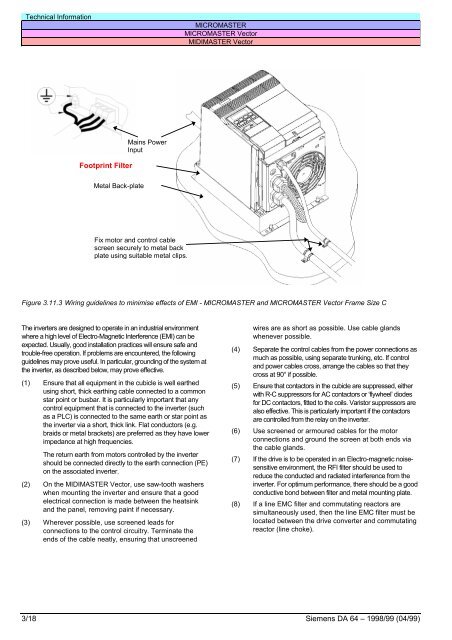
Technical InformationMICROMASTERMICROMASTER VectorMIDIMASTER VectorFootprint FilterMains PowerInputMetal Back-plateFix motor and control cablescreen securely to metal backplate using suitable metal clips.Figure 3.11.3 Wiring guidelines to minimise effects of EMI - MICROMASTER and MICROMASTER Vector Frame Size CThe inverters are designed to operate in an industrial environmentwhere a high level of Electro-Magnetic Interference (EMI) can beexpected. Usually, good installation practices will ensure safe andtrouble-free operation. If problems are encountered, the followingguidelines may prove useful. In particular, grounding of the system atthe inverter, as described below, may prove effective.(1) Ensure that all equipment in the cubicle is well earthedusing short, thick earthing cable connected to a commonstar point or busbar. It is particularly important that anycontrol equipment that is connected to the inverter (suchas a PLC) is connected to the same earth or star point asthe inverter via a short, thick link. Flat conductors (e.g.braids or metal brackets) are preferred as they have lowerimpedance at high frequencies.The return earth from motors controlled by the invertershould be connected directly to the earth connection (PE)on the associated inverter.(2) On the MIDIMASTER Vector, use saw-tooth washerswhen mounting the inverter and ensure that a goodelectrical connection is made between the heatsinkand the panel, removing paint if necessary.(3) Wherever possible, use screened leads forconnections to the control circuitry. Terminate theends of the cable neatly, ensuring that unscreenedwires are as short as possible. Use cable glandswhenever possible.(4) Separate the control cables from the power connections asmuch as possible, using separate trunking, etc. If controland power cables cross, arrange the cables so that theycross at 90° if possible.(5) Ensure that contactors in the cubicle are suppressed, eitherwith R-C suppressors for AC contactors or ‘flywheel’ diodesfor DC contactors, fitted to the coils. Varistor suppressors arealso effective. This is particularly important if the contactorsare controlled from the relay on the inverter.(6) Use screened or armoured cables for the motorconnections and ground the screen at both ends viathe cable glands.(7) If the drive is to be operated in an Electro-magnetic noisesensitiveenvironment, the RFI filter should be used toreduce the conducted and radiated interference from theinverter. For optimum performance, there should be a goodconductive bond between filter and metal mounting plate.(8) If a line EMC filter and commutating reactors aresimultaneously used, then the line EMC filter must belocated between the drive converter and commutatingreactor (line choke).3/18 Siemens DA 64 – 1998/99 (04/99)


