MicroMaster 6SE92 - ECT Sales & Service
MicroMaster 6SE92 - ECT Sales & Service
MicroMaster 6SE92 - ECT Sales & Service

You also want an ePaper? Increase the reach of your titles
YUMPU automatically turns print PDFs into web optimized ePapers that Google loves.
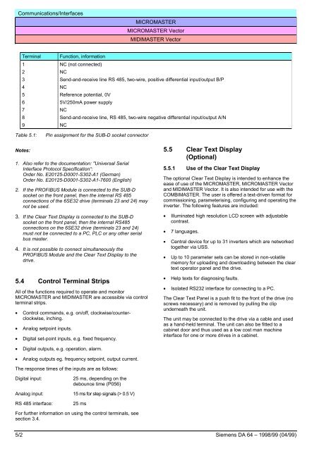
Communications/InterfacesMICROMASTERMICROMASTER VectorMIDIMASTER VectorTerminal Function, information1 NC (not connected)2 NC3 Send-and-receive line RS 485, two-wire, positive differential input/output B/P4 NC5 Reference potential, 0V6 5V/250mA power supply7 NC8 Send-and-receive line, RS 485, two-wire negative differential input/output A/N9 NCTable 5.1:Pin assignment for the SUB-D socket connectorNotes:1. Also refer to the documentation: "Universal SerialInterface Protocol Specification“:Order No. E20125-D0001-S302-A1 (German)Order No. E20125-D0001-S302-A1-7600 (English)2. If the PROFIBUS Module is connected to the SUB-Dsocket on the front panel, then the internal RS 485connections of the 6SE32 drive (terminals 23 and 24) maynot be used.3. If the Clear Text Display is connected to the SUB-Dsocket on the front panel, then the internal RS485connections on the 6SE32 drive (terminals 23 and 24)must not be connected to a PC, PLC or any other serialbus master.4. It is not possible to connect simultaneously thePROFIBUS Module and the Clear Text Display to thedrive.5.4 Control Terminal StripsAll of the functions required to operate and monitorMICROMASTER and MIDIMASTER are accessible via controlterminal strips.• Control commands, e.g. on/off, clockwise/counterclockwise,inching.• Analog setpoint inputs.• Digital set-point inputs, e.g. fixed frequency.5.5 Clear Text Display(Optional)5.5.1 Use of the Clear Text DisplayThe optional Clear Text Display is intended to enhance theease of use of the MICROMASTER, MICROMASTER Vectorand MIDIMASTER Vector. It is also intended for use with theCOMBIMASTER. The user is offered a text-driven format forcommissioning, parameterising, configuring and operating theinverter. The following features are included:• Illuminated high resolution LCD screen with adjustablecontrast.• 7 languages.• Central device for up to 31 inverters which are networkedtogether via USS.• Up to 10 parameter sets can be stored in non-volatilememory for uploading and downloading between the cleartext operator panel and the drive.• Help texts for diagnosing faults.• Isolated RS232 interface for connecting to a PC.The Clear Text Panel is a push fit to the front of the drive (noscrews necessary) and is removed by pulling the clipunderneath the unit.The unit may be connected to the drive via a cable and usedas a hand-held terminal. The unit can also be fitted to acabinet door and thus used as a low cost man machineinterface for one or more drives in a cabinet.• Digital outputs, e.g. operation, alarm.• Analog outputs eg. frequency setpoint, output current.The response times of the inputs are as follows:Digital input:25 ms, depending on thedebounce time (P056)Analog input: 15 ms for step signals (> 0.5 V)RS 485 interface:25 msFor further information on using the control terminals, seesection 3.4.5/2 Siemens DA 64 – 1998/99 (04/99)