MicroMaster 6SE92 - ECT Sales & Service
MicroMaster 6SE92 - ECT Sales & Service
MicroMaster 6SE92 - ECT Sales & Service

You also want an ePaper? Increase the reach of your titles
YUMPU automatically turns print PDFs into web optimized ePapers that Google loves.
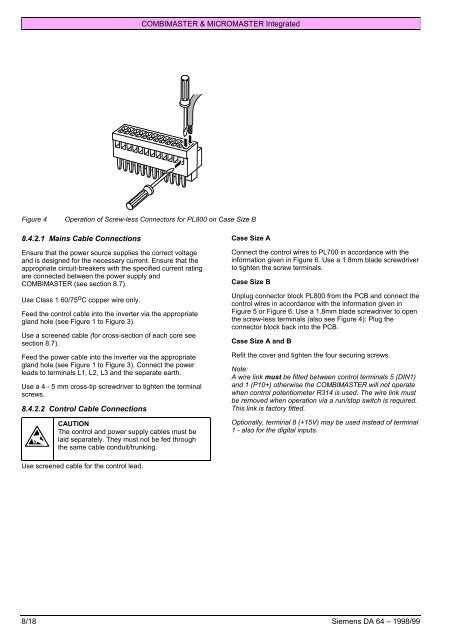
COMBIMASTER & MICROMASTER IntegratedFigure 4Operation of Screw-less Connectors for PL800 on Case Size B8.4.2.1 Mains Cable ConnectionsEnsure that the power source supplies the correct voltageand is designed for the necessary current. Ensure that theappropriate circuit-breakers with the specified current ratingare connected between the power supply andCOMBIMASTER (see section 8.7).Use Class 1 60/75 o C copper wire only.Feed the control cable into the inverter via the appropriategland hole (see Figure 1 to Figure 3).Use a screened cable (for cross-section of each core seesection 8.7).Feed the power cable into the inverter via the appropriategland hole (see Figure 1 to Figure 3). Connect the powerleads to terminals L1, L2, L3 and the separate earth.Use a 4 - 5 mm cross-tip screwdriver to tighten the terminalscrews.8.4.2.2 Control Cable ConnectionsCAUTIONThe control and power supply cables must belaid separately. They must not be fed throughthe same cable conduit/trunking.Case Size AConnect the control wires to PL700 in accordance with theinformation given in Figure 6. Use a 1.8mm blade screwdriverto tighten the screw terminals.Case Size BUnplug connector block PL800 from the PCB and connect thecontrol wires in accordance with the information given inFigure 5 or Figure 6. Use a 1.8mm blade screwdriver to openthe screw-less terminals (also see Figure 4): Plug theconnector block back into the PCB.Case Size A and BRefit the cover and tighten the four securing screws.Note:A wire link must be fitted between control terminals 5 (DIN1)and 1 (P10+) otherwise the COMBIMASTER will not operatewhen control potentiometer R314 is used. The wire link mustbe removed when operation via a run/stop switch is required.This link is factory fitted.Optionally, terminal 8 (+15V) may be used instead of terminal1 - also for the digital inputs.Use screened cable for the control lead.8/18 Siemens DA 64 – 1998/99