MicroMaster 6SE92 - ECT Sales & Service
MicroMaster 6SE92 - ECT Sales & Service
MicroMaster 6SE92 - ECT Sales & Service

Create successful ePaper yourself
Turn your PDF publications into a flip-book with our unique Google optimized e-Paper software.
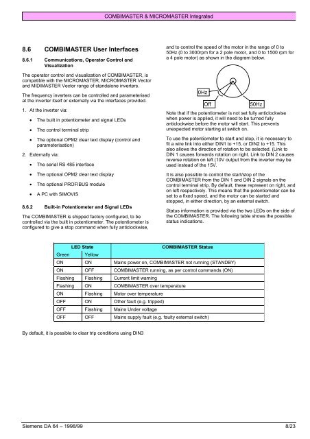
COMBIMASTER & MICROMASTER Integrated8.6 COMBIMASTER User Interfaces8.6.1 Communications, Operator Control andVisualizationThe operator control and visualization of COMBIMASTER, iscompatible with the MICROMASTER, MICROMASTER Vectorand MIDIMASTER Vector range of standalone inverters.The frequency inverters can be controlled and parameterisedat the inverter itself or externally via the interfaces provided.1. At the inverter via:• The built in potentiometer and signal LEDs• The control terminal strip• The optional OPM2 clear text display (control andparameterisation)2. Externally via:• The serial RS 485 interface• The optional OPM2 clear text display• The optional PROFIBUS module• A PC with SIMOVIS8.6.2 Built-in Potentiometer and Signal LEDsThe COMBIMASTER is shipped factory configured, to becontrolled via the built in potentiometer. The potentiometer isconfigured to give a stop command when fully anticlockwise,and to control the speed of the motor in the range of 0 to50Hz (0 to 3000rpm for a 2 pole motor, and 0 to 1500 rpm fora 4 pole motor) as shown in the diagram below.0HzOff50HzNote that if the potentiometer is not set fully anticlockwisewhen power is applied, it will need to be turned fullyanticlockwise before the motor will start. This preventsunexpected motor starting at switch on.To use the potentiometer to start and stop, it is necessary tofit a wire link into either DIN1 to +15, or DIN2 to +15. Thisalso allows the direction of rotation to be selected. (Link toDIN 1 causes forwards rotation on right. Link to DIN 2 causesreverse rotation on left (10V output from the inverter may beused instead of the 15V.It is also possible to control the start/stop of theCOMBIMASTER from the DIN 1 and DIN 2 signals on thecontrol terminal strip. By default, these represent on right, andon left respectively. This means that the potentiometer can beset to a fixed speed, and the motor can be started andstopped, in either direction, by an external switch.Status information is provided via the two LEDs on the side ofthe COMBIMASTER. The following table shows the possiblestatus indications.LED StateCOMBIMASTER StatusGreen YellowON ON Mains power on, COMBIMASTER not running (STANDBY)ON OFF COMBIMASTER running, as per control commands (ON)Flashing Flashing Current limit warningFlashing ON COMBIMASTER over temperatureON Flashing Motor over temperatureOFF ON Other fault (e.g. tripped)OFF Flashing Mains Under voltageOFF OFF Mains supply fault (e.g. faulty external switch)By default, it is possible to clear trip conditions using DIN3Siemens DA 64 – 1998/99 8/23