MicroMaster 6SE92 - ECT Sales & Service
MicroMaster 6SE92 - ECT Sales & Service
MicroMaster 6SE92 - ECT Sales & Service

You also want an ePaper? Increase the reach of your titles
YUMPU automatically turns print PDFs into web optimized ePapers that Google loves.
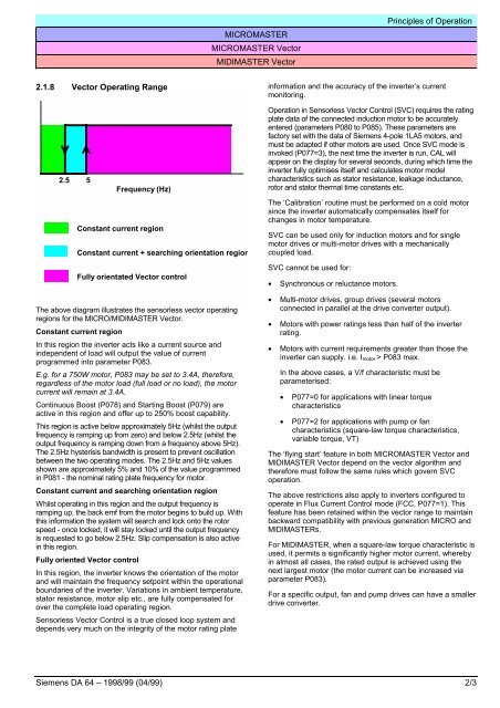
MICROMASTERMICROMASTER VectorMIDIMASTER VectorPrinciples of Operation2.1.8 Vector Operating Rangeinformation and the accuracy of the inverter’s currentmonitoring.2.55Frequency (Hz)Constant current regionConstant current + searching orientation regionFully orientated Vector controlOperation in Sensorless Vector Control (SVC) requires the ratingplate data of the connected induction motor to be accuratelyentered (parameters P080 to P085). These parameters arefactory set with the data of Siemens 4-pole 1LA5 motors, andmust be adapted if other motors are used. Once SVC mode isinvoked (P077=3), the next time the inverter is run, CAL willappear on the display for several seconds, during which time theinverter fully optimises itself and calculates motor modelcharacteristics such as stator resistance, leakage inductance,rotor and stator thermal time constants etc.The ‘Calibration’ routine must be performed on a cold motorsince the inverter automatically compensates itself forchanges in motor temperature.SVC can be used only for induction motors and for singlemotor drives or multi-motor drives with a mechanicallycoupled load.SVC cannot be used for:• Synchronous or reluctance motors.The above diagram illustrates the sensorless vector operatingregions for the MICRO/MIDIMASTER Vector.Constant current regionIn this region the inverter acts like a current source andindependent of load will output the value of currentprogrammed into parameter P083.E.g. for a 750W motor, P083 may be set to 3.4A, therefore,regardless of the motor load (full load or no load), the motorcurrent will remain at 3.4A.Continuous Boost (P078) and Starting Boost (P079) areactive in this region and offer up to 250% boost capability.This region is active below approximately 5Hz (whilst the outputfrequency is ramping up from zero) and below 2.5Hz (whilst theoutput frequency is ramping down from a frequency above 5Hz).The 2.5Hz hysterisis bandwidth is present to prevent oscillationbetween the two operating modes. The 2.5Hz and 5Hz valuesshown are approximately 5% and 10% of the value programmedin P081 - the nominal rating plate frequency for motor.Constant current and searching orientation regionWhilst operating in this region and the output frequency isramping up, the back emf from the motor begins to build up. Withthis information the system will search and lock onto the rotorspeed - once locked, it will stay locked until the output frequencyis requested to go below 2.5Hz. Slip compensation is also activein this region.Fully oriented Vector controlIn this region, the inverter knows the orientation of the motorand will maintain the frequency setpoint within the operationalboundaries of the inverter. Variations in ambient temperature,stator resistance, motor slip etc., are fully compensated forover the complete load operating region.Sensorless Vector Control is a true closed loop system anddepends very much on the integrity of the motor rating plate• Multi-motor drives, group drives (several motorsconnected in parallel at the drive converter output).• Motors with power ratings less than half of the inverterrating.• Motors with current requirements greater than those theinverter can supply. i.e. I motor > P083 max.In the above cases, a V/f characteristic must beparameterised:• P077=0 for applications with linear torquecharacteristics• P077=2 for applications with pump or fancharacteristics (square-law torque characteristics,variable torque, VT)The ‘flying start’ feature in both MICROMASTER Vector andMIDIMASTER Vector depend on the vector algorithm andtherefore must follow the same rules which govern SVCoperation.The above restrictions also apply to inverters configured tooperate in Flux Current Control mode (FCC, P077=1). Thisfeature has been retained within the vector range to maintainbackward compatibility with previous generation MICRO andMIDIMASTERs.For MIDIMASTER, when a square-law torque characteristic isused, it permits a significantly higher motor current, wherebyin almost all cases, the rated output is achieved using thenext largest motor (the motor current can be increased viaparameter P083).For a specific output, fan and pump drives can have a smallerdrive converter.Siemens DA 64 – 1998/99 (04/99) 2/3