MicroMaster 6SE92 - ECT Sales & Service
MicroMaster 6SE92 - ECT Sales & Service
MicroMaster 6SE92 - ECT Sales & Service

Create successful ePaper yourself
Turn your PDF publications into a flip-book with our unique Google optimized e-Paper software.
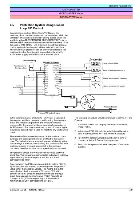
MICROMASTERMICROMASTER VectorMIDIMASTER VectorStandard Applications4.5 Ventilation System Using ClosedLoop PID ControlIn applications such as Clean Room Ventilators, it isnecessary for a constant pressure to be maintained within theventilator. This can be achieved by driving the fan within theventilator with a MICROMASTER, MICROMASTER Vector orMIDIMASTER Vector which have built-in PID controllers (PI inthe case of MICROMASTER) allowing a closed loop processcontrol system to be designed without external controllers.The actual value processor can be directly connected to theanalogue input of the drive and powered directly from the+15V power supply available from the terminal block.Potentiometer forflow rate settingThree Phase415V Mains inputEarthL1L2L3Panel MountingMIDIMASTER Vector1+10V20V3Ain1+4Ain1-10Ain2+11Ain2-5Din16Din27Din38Din416Din517Din69+15VPEL/L1N/L2L3Dout1 NCDout1 NODout1 ComDout2 NODout2 comPTC1PTC2Aout2+Aout2-PEUVWDC+ DC-181920212212Aout1+13Aout1-24RS485P25RS485N1415Panel MountingLamp indicating faultLamp indicating drive runningGauge showing motor frequencyGauge showing motor currentFanPressure SensorAnalogue PID feedback signalIn the example shown, a MIDIMASTER Vector is used andthe required ventilator pressure is set by using the analogueinput. The feedback signal from the pressure sensor isconnected to the second analogue input which is configuredfor PID control. The drive is switched on and off via the digitalinput and a second input is used for resetting any faults whichoccur.The drive itself is mounted within the cabinet and the controlswitches and speed potentiometer are fitted to the cabinetdoor. Two indicator lamps are used, connected directly to theoutput relays to indicate drive running and fault occurred. Twoanalogue gauges are used, connected to the analogueoutputs of the drive, to show motor speed and motor current.The following procedure should be followed to set the P, I andD terms:1. If possible, select fast ramp up and ramp down times(P002, P003).2. In this case P211 (0% setpoint value) should be set to25% to correspond to the 1 Bar minimum pressure.3. P212 (100% setpoint value) should be set to 50% tocorrespond to the 2 Bar maximum pressure.4. Switch on the system and allow the speed of the fan tostabilise.The pressure across the ventilator can be varied between 1and 2 Bar. The pressure sensor selected outputs a 4 to 20mAsignal whereby 4mA corresponds to 0 Bar and 20mAcorresponds to 4 Bar.Note that when the PID mode is enabled (by setting P201 to1) the setpoints are referred to percentages of the processvalue rather than absolute values. This means that in theexample described, a setpoint of 50 means 50% whichequates to 5 Bar. Since the setpoint is from the analogueinput, the analogue maximum value (P022) needs to bechanged to 50 (50% corresponding to 8 Bar) and theminimum to 25 (25% corresponding to 4 Bar).Siemens DA 64 – 1998/99 (04/99) 4/9