MicroMaster 6SE92 - ECT Sales & Service
MicroMaster 6SE92 - ECT Sales & Service
MicroMaster 6SE92 - ECT Sales & Service

Create successful ePaper yourself
Turn your PDF publications into a flip-book with our unique Google optimized e-Paper software.
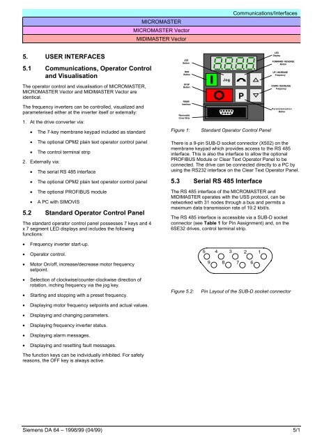
MICROMASTERMICROMASTER VectorMIDIMASTER VectorCommunications/Interfaces5. USER INTERFACES5.1 Communications, Operator Controland VisualisationThe operator control and visualisation of MICROMASTER,MICROMASTER Vector and MIDIMASTER Vector areidentical.The frequency inverters can be controlled, visualized andparameterised either at the inverter itself or externally:1. At the drive converter via:• The 7-key membrane keypad included as standardJOGButtonRUNButtonSTOPButtonRS485InterfaceRemovableCover StripFigure 1:JogPStandard Operator Control PanelLEDDisplayFORWARD / REVERSEButtonUP / INCREASEFrequencyDOWN / DECREASEFrequencyParameterisationButton• The optional OPM2 plain text operator control panel• The control terminal strip2. Externally via:• The serial RS 485 interface• The optional OPM2 plain text operator control panel• The optional PROFIBUS module• A PC with SIMOVIS5.2 Standard Operator Control PanelThe standard operator control panel possesses 7 keys and 4x 7 segment LED displays and includes the followingfunctions:There is a 9-pin SUB-D socket connector (X502) on themembrane keypad which provides access to the RS 485interface. This is also the interface to allow the optionalPROFIBUS Module or Clear Text Operator Panel to beconnected. The drive can be connected directly to a PC byusing the RS232 interface on the Clear Text Operator Panel.5.3 Serial RS 485 InterfaceThe RS 485 interface of the MICROMASTER andMIDIMASTER operates with the USS protocol, can benetworked with 31 nodes through a bus and permits amaximum data transmission rate of 19.2 kbit/s.The RS 485 interface is accessible via a SUB-D socketconnector (see Table 1 for Pin Assignment) and, on the6SE32 drives, control terminal strip.• Frequency inverter start-up.• Operator control.54321• Motor On/off, increase/decrease motor frequencysetpoint.9876• Selection of clockwise/counter-clockwise direction ofrotation, inching frequency via the jog key.• Starting and stopping with a preset frequency.• Displaying motor frequency setpoints and actual values.• Displaying and changing parameters.• Displaying frequency inverter status.• Displaying alarm messages.• Displaying and resetting fault messages.The function keys can be individually inhibited. For safetyreasons, the OFF key is always active.Figure 5.2:Pin Layout of the SUB-D socket connectorSiemens DA 64 – 1998/99 (04/99) 5/1