State of the Art Hydraulic Systems for Movable Bridges
State of the Art Hydraulic Systems for Movable Bridges
State of the Art Hydraulic Systems for Movable Bridges
Create successful ePaper yourself
Turn your PDF publications into a flip-book with our unique Google optimized e-Paper software.
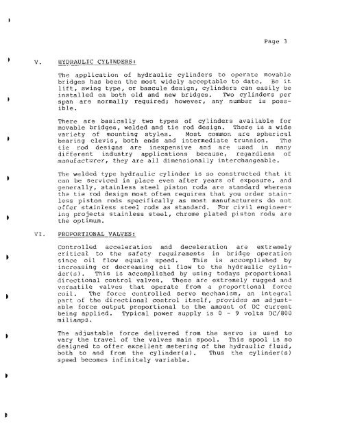
Page 3HYDRAULIC CYLINDERS:The application <strong>of</strong> hydraulic cylinders to operate movablebridges has been <strong>the</strong> most widely acceptable to date. Be itlift, swing type, or bascule design, cylinders can easily beinstalled on both old and new bridges. Two cylinders perspan are normally required; however, any number is possible.There are basically two types <strong>of</strong> cylinders available <strong>for</strong>movable bridges, welded and tie rod design. There is a widevariety <strong>of</strong> mounting styles. Most common are sphericalbearing clevis, both ends and intermediate trunnion. Thetie rod designs are inexpensive and are used in manydifferent industry applications because, regardless <strong>of</strong>manufacturer, <strong>the</strong>y are all dimensionally interchangeable.The welded type hydraulic cylinder is so constructed that itcan be serviced in place even after years <strong>of</strong> exposure, andgenerally, stainless steel piston rods are standard whereas<strong>the</strong> tie rod design most <strong>of</strong>ten requires that you order stainlesspiston rods speciEically as most manufacturers do not<strong>of</strong>fer stainless steel rods as standard. For civil engineeringprojects stainless steel, chrome plated piston rods are<strong>the</strong> optimum.'$1.PROPORTIONAL VALVES:Controlled acceleration and deceleration are extremelycritical to <strong>the</strong> safety requirements in bridge operationsince oil flow equals speed. This is accomplished byincreasing or decreasing oil flow to <strong>the</strong> hydraulic cylinder(~).This is accomplished by using todays proportionaldirectional control valves. These are extremely rugged andversatile valves that operate from a proportional <strong>for</strong>cecoil. The <strong>for</strong>ce controlled servo mechanism, an int.egra1part <strong>of</strong> <strong>the</strong> directional control itself, provides an adjustable<strong>for</strong>ce output proportional to <strong>the</strong> amount oE DC currentbeing applied. Typical power supply is 0 - 9 volts DC/800miliamps.The adjustable <strong>for</strong>ce delivered from <strong>the</strong> servo is used tovary <strong>the</strong> travel <strong>of</strong> <strong>the</strong> valves main spool. This spool is sodesigned to <strong>of</strong>fer excellent metering <strong>of</strong> <strong>the</strong> hydraulic flu~d,both to and from <strong>the</strong> cylinder(s). Thus <strong>the</strong> cylinder(s)speed becomes infinitely variable.


