

Introduction to Autodesk Inventor for F1 in Schools
Introduction to Autodesk Inventor for F1 in Schools
Introduction to Autodesk Inventor for F1 in Schools

You also want an ePaper? Increase the reach of your titles
YUMPU automatically turns print PDFs into web optimized ePapers that Google loves.
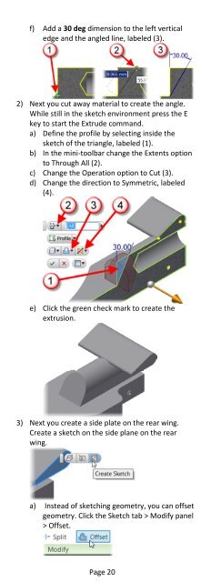
f) Add a 30 deg dimension <strong>to</strong> the left verticaledge and the angled l<strong>in</strong>e, labeled (3).2) Next you cut away material <strong>to</strong> create the angle.While still <strong>in</strong> the sketch environment press the Ekey <strong>to</strong> start the Extrude command.a) Def<strong>in</strong>e the profile by select<strong>in</strong>g <strong>in</strong>side thesketch of the triangle, labeled (1).b) In the m<strong>in</strong>i-<strong>to</strong>olbar change the Extents option<strong>to</strong> Through All (2).c) Change the Operation option <strong>to</strong> Cut (3).d) Change the direction <strong>to</strong> Symmetric, labeled(4).e) Click the green check mark <strong>to</strong> create theextrusion.3) Next you create a side plate on the rear w<strong>in</strong>g.Create a sketch on the side plane on the rearw<strong>in</strong>g.a) Instead of sketch<strong>in</strong>g geometry, you can offsetgeometry. Click the Sketch tab > Modify panel> Offset.Page 20