PolyChain® GT Timing Belts - Walther Flender
PolyChain® GT Timing Belts - Walther Flender
PolyChain® GT Timing Belts - Walther Flender

Create successful ePaper yourself
Turn your PDF publications into a flip-book with our unique Google optimized e-Paper software.
<strong>Walther</strong> <strong>Flender</strong> Gruppe<br />
PolyChain ® <strong>GT</strong> <strong>Timing</strong> <strong>Belts</strong> PAGE 27<br />
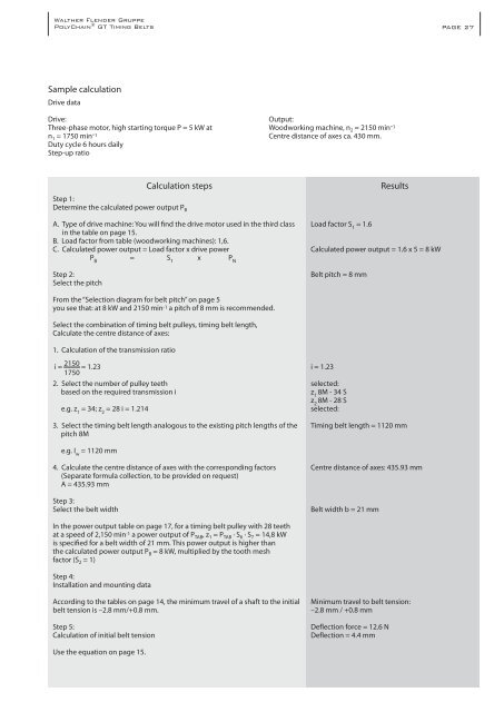
Sample calculation<br />
Drive data<br />
Drive:<br />
Three-phase motor, high starting torque P = 5 kW at<br />
n 1 = 1750 min-1<br />
Duty cycle 6 hours daily<br />
Step-up ratio<br />
Step 1:<br />
Determine the calculated power output P B<br />
Output:<br />
Woodworking machine, n 2 = 2150 min-1<br />
Centre distance of axes ca. 430 mm.<br />
Calculation steps Results<br />
A. Type of drive machine: You will find the drive motor used in the third class<br />
in the table on page 15.<br />
B. Load factor from table (woodworking machines): 1,6.<br />
C. Calculated power output = Load factor x drive power<br />
P B = S 1 x P N<br />
Step 2:<br />
Select the pitch<br />
From the “Selection diagram for belt pitch” on page 5<br />
you see that: at 8 kW and 2150 min -1 a pitch of 8 mm is recommended.<br />
Select the combination of timing belt pulleys, timing belt length,<br />
Calculate the centre distance of axes:<br />
1. Calculation of the transmission ratio<br />
i = 2150 = 1.23<br />
1750<br />
2. Select the number of pulley teeth<br />
based on the required transmission i<br />
e.g. z 1 = 34; z 2 = 28 i = 1.214<br />
3. Select the timing belt length analogous to the existing pitch lengths of the<br />
pitch 8M<br />
e.g. I w = 1120 mm<br />
4. Calculate the centre distance of axes with the corresponding factors<br />
(Separate formula collection, to be provided on request)<br />
A = 435.93 mm<br />
Step 3:<br />
Select the belt width<br />
In the power output table on page 17, for a timing belt pulley with 28 teeth<br />
at a speed of 2,150 min -1 a power output of P TAB, z 1 = P TAB · S 6 · S 7 = 14,8 kW<br />
is specified for a belt width of 21 mm. This power output is higher than<br />
the calculated power output P B = 8 kW, multiplied by the tooth mesh<br />
factor (S 2 = 1)<br />
Step 4:<br />
Installation and mounting data<br />
According to the tables on page 14, the minimum travel of a shaft to the initial<br />
belt tension is –2.8 mm/+0.8 mm.<br />
Step 5:<br />
Calculation of initial belt tension<br />
Use the equation on page 15.<br />
Load factor S 1 = 1.6<br />
Calculated power output = 1.6 x 5 = 8 kW<br />
Belt pitch = 8 mm<br />
i = 1.23<br />
selected:<br />
z 1 8M - 34 S<br />
z 2 8M - 28 S<br />
selected:<br />
<strong>Timing</strong> belt length = 1120 mm<br />
Centre distance of axes: 435.93 mm<br />
Belt width b = 21 mm<br />
Minimum travel to belt tension:<br />
–2.8 mm / +0.8 mm<br />
Deflection force = 12.6 N<br />
Deflection = 4.4 mm