download LR pdf - Kabk
download LR pdf - Kabk
download LR pdf - Kabk

Create successful ePaper yourself
Turn your PDF publications into a flip-book with our unique Google optimized e-Paper software.
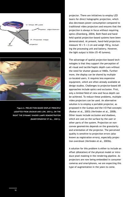
Figure 6. Projection-based display principle(adapted from (Raskar and Low, 2001)), on theright the dynamic shader lamps demonstration(Bandyopadhyay et al., 2001)).projector. There are initiatives to employ LEDlasers for direct holographic projection, whichalso decreases power consumption compared totraditional video projectors and ensures that theprojection is always in focus without requiringoptics (Eisenberg, 2004). Both fixed and handheldspatial projection-based systems have beendemonstrated. At present, hand-held projectorsmeasure 10 × 5 × 2 cm and weigh 150 g, includingthe processing unit and battery. However,the light output is little (15–45 lumens).The advantage of spatial projection-based technologiesis that they support the perception ofall visual and tactile/haptic depth cues withoutthe need for shutter glasses or HMDs. Furthermore,the display can be shared by multipleco-located users. It requires less expensiveequipment, which are often already available atdesign studios. Challenges to projector-based ARapproaches include optics and occlusion. First,only a limited field of view and focus depth canbe achieved. To reduce these problems, multiplevideo projectors can be used. An alternativeso lution is to employ a portable projector, asproposed in the iLamps and the I/O Pad concepts(Raskar et al., 2003) (Verlinden et al., 2008).Other issues include occlusion and shadows,which are cast on the surface by the user orother parts of the system. Projection on nonconvexgeometries depends on the granularityand orientation of the projector. The perceivedquality is sensitive to projection errors (alsoknown as registration errors), especially projectionovershoot (Verlinden et al., 2003b).A solution for this problem is either to include anoffset (dilatation) of the physical model or introducepixel masking in the rendering pipeline. Asprojectors are now being embedded in consumercameras and smartphones, we are expecting thistype of augmentation in the years to come.3. Input TechnologiesIn order to merge the digital and physical, positionand orientation tracking of the physicalcomponents is required. Here, we will discusstwo different types of input technologies: trackingand event sensing. Furthermore, we willbriefly discuss other input modalities.3.1 Position trackingWelch and Foxlin (2002) presented a comprehensiveoverview of the tracking principlesthat are currently available. In the ideal case,the measurement should be as unobtrusive andinvisible as possible while still offering accurateand rapid data. They concluded that there iscurrently no ideal solution (‘silver bullet’) forposition tracking in general, but some respectablealternatives are available. Table 2 summarisesthe most important characteristics ofthese tracking methods for Augmented Realitypurposes. The data have been gathered fromcommercially available equipment (the AscensionFlock of Birds, ARToolkit, Optotrack,Tracking typeSize oftracker(mm)Magnetic 16x16x16 2OpticalpassiveOpticalactive80x80x0.01 >1010x10x5 >10Ultrasound 20x20x10 1MechanicallinkageLaserscanningdefined byworkingenvelopenoneTypicalnumber oftrackers1infiniteLogitech 3D Tracker, Microscribe and Minolta VI-900). All these should be considered for objecttracking in Augmented prototyping scenarios.There are significant differences in the tracker/marker size, action radius and accuracy. Asthe physical model might consist of a numberof parts or a global shape and some additionalcomponents (e.g., buttons), the number of itemsto be tracked is also of importance. For simpletracking scenarios, either magnetic or passiveoptical technologies are often used.In some experiments we found out that a projectorcould not be equipped with a standard Flockof Birds 3D magnetic tracker due to interference.Other tracking techniques should be usedfor this paradigm. For example, the ARToolkitemploys complex patterns and a regular webcamerato determine the position, orientationand identification of the marker. This is done bymeasuring the size, 2D position and perspectivedistortion of a known rectangular marker, cf.Figure 7 (Kato and Billinghurst, 1999).Passive markers enable a relatively untetheredsystem, as no wiring is necessary. The opticalmarkers are obtrusive when markers are visibleto the user while handling the object. Althoughcomputationally intensive, marker-less opticalActionradius/accuracy1.5 m(1 mm)3 m(1 mm)3 m(0.5 mm)1 m(3 mm)0.7 m(0.1 mm)2 m( 0.2mm)DOFIssues6 Ferro-magnetic interference6 line of sight3 line of sight, wired connections6 line of sight56limited degrees of freedom,inertialine of sight, frequency, objectrecognition50Table 2. Summary of tracking technologies.51