BM31 - BEKO TECHNOLOGIES GmbH
BM31 - BEKO TECHNOLOGIES GmbH
BM31 - BEKO TECHNOLOGIES GmbH

Create successful ePaper yourself
Turn your PDF publications into a flip-book with our unique Google optimized e-Paper software.
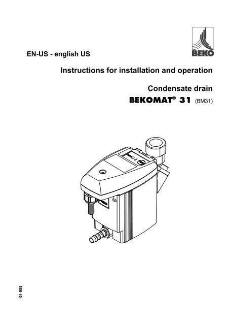
EN-US - english USInstructions for installation and operationCondensate drain<strong>BEKO</strong>MAT ® 31 (<strong>BM31</strong>)01-988
Dear customer,Thank you for deciding in favor of the <strong>BEKO</strong>MAT ® 31 condensate drain. Please read the installation andoperating instructions carefully before mounting and starting up the <strong>BEKO</strong>MAT ® 31, and follow our directions.Perfect functioning of the <strong>BEKO</strong>MAT ® 31, and thus reliable condensate discharge, can only be guaranteedwhen the provisions and notes stipulated here are strictly adhered to.2 <strong>BEKO</strong>MAT® 31
1 Pictograms and symbols ........................................................................................................................42 Safety instructions ..................................................................................................................................43 Proper use..............................................................................................................................................54 Exclusion from the scope of application.................................................................................................65 Technical data ........................................................................................................................................76 Dimension drawing.................................................................................................................................87 Function..................................................................................................................................................98 Installation ............................................................................................................................................109 Electrical installation.............................................................................................................................1310 Control and maintenance .....................................................................................................................1611 Troubleshooting and fault elimination ..................................................................................................1912 Elements and components...................................................................................................................2013 Recommended spare parts..................................................................................................................2114 Accessories ..........................................................................................................................................2115 Declaration of conformity .....................................................................................................................22<strong>BEKO</strong>MAT® 31 3
Pos: 2 /Beko Technische Dokumentati on/Pi ktogramme/Anl eitung beachten blau @ 0\mod_1213268300255_15098.doc @ 15193 @ @ 1Pos: 3 /Beko Technische Dokumentati on/Pi ktogramme/Anl eitung beachten s/w T ypenschild @ 1\mod_1290772180142_15098.doc @ 20492 @ @ 1Pos: 4 /Beko Technische Dokumentati on/Pi ktogramme/Gefahr Warnung Vorsicht s/w @ 0\mod_1213265685174_15098.doc @ 15189 @ @ 1Pos: 5 /Beko Technische Dokumentati on/Pi ktogramme/G+W+ V N etzspannung s/w @ 0\mod_1213266193701_15098.doc @ 15191 @ @ 1Pos: 7 /Beko Technische Dokumentati on/Gl obal e T exte/Allgemei ner Hi nweis BM @ 0\mod_1183615737313_15098.doc @ 15099 @ @ 1Pos: 8 /Beko Technische Dokumentati on/Sicherheit/Hi nweis Anlei tung <strong>BEKO</strong> U SA @ 1\mod_1251202926517_15098.doc @ 15906 @ @ 1Pos: 9 /Beko Technische Dokumentati on/Sicherheit/Gefahr Druckluft @ 0\mod_1184148143854_15098.doc @ 15121 @ @ 1Pos: 10 /Beko T echnische D okumentati on/Sicher hei t/Maßnahmen Druckluft BM @ 0\mod_1184148284291_15098.doc @ 15123 @ @ 1Pos: 11 /Beko T echnische D okumentati on/Sicher hei t/Gefahr Netzspannung @ 0\mod_1184148186948_15098.doc @ 15122 @ @ 1Pictograms and symbolsPos: 1 /Beko Technische Dokumentati on/Ü berschriften/1/Pi ktogramme und Symbol e @ 1\mod_1290773595840_15098.doc @ 20525 @ 11 @ 11 Pictograms and symbolsObserve the installation and operating instructionsObserve the installation and operating instructions(on the type plate)General danger symbol (danger, warning, caution)General danger symbol (danger, warning, caution) for supply voltage and supply voltagecarryingplants componentsPos: 6 /Beko Technische Dokumentati on/Ü berschriften/1/Sicherheitshinweise @ 0\mod_1183637609261_15098.doc @ 15102 @ 1 @ 12 Safety instructionsPlease check whether or not these instructions correspond to the device type.Adhere to all advice given in these operating instructions. They include essential informationwhich must be observed during the installation, operation and maintenance. Therefore it isimperative for the service technician and the responsible operator / technical staff to read theseoperating instructions prior to installation, start-up and maintenance.The operating instructions must be accessible at any time at the place of application of the<strong>BEKO</strong>MAT ® 31.In addition to these operating instructions, local or national regulations must be complied with,if necessary.Make sure that the <strong>BEKO</strong>MAT ® 31 is operated only within the permissible limit values indicatedon the ID plate. Any deviation involves a risk for persons and materials, and may result in malfunctionand service failures.If you have any queries regarding these installation- and operating instructions, please contact<strong>BEKO</strong> <strong>TECHNOLOGIES</strong> CORP.Measures:Danger!Compressed air!Risk of serious injury or death through contact with quickly or suddenly escaping compressedair or through bursting plant components or plant components which are notsecured.• Do not exceed the maximum operating pressure (see type plate).• Only carry out service measures when the system is pressure less.• Use pressure-resistant installation material only.• The feed pipe must be tubed firmly. Discharge pipe: short, fixed pressure hose onto pressure-resistantpipe.• Make sure that persons or objects cannot be hit by condensate or escaping compressed air.4 <strong>BEKO</strong>MAT® 31
Pos: 20 /Beko T echnische D okumentati on/Besti mmungsgemäß e Ver wendung/<strong>BEKO</strong>M AT/Ausschl uß Anwendung BM 31/32/33 @ 0\mod_1236003837511_15098.doc @ 15309 @ @ 1Pos: 21 /Beko T echnische D okumentati on/Besti mmungsgemäß e Ver wendung/<strong>BEKO</strong>M AT/Ausschl uß Anwendung BM nicht für frostgefähr dete Bereiche (Zusatz) @ 0\mod_1216106439206_15098.doc @ 15249 @ @ 1Pos: 22 /Beko T echnische D okumentati on/Besti mmungsgemäß e Ver wendung/<strong>BEKO</strong>M AT/Ausschl uß Anwendung BM 31/32 nicht fürC O2- Anwendg. @ 0\mod_1242828696240_15098.doc @ 15316 @ @ 1Pos: 23 /---- Seitenumbr uch ---- @ 0\mod_1157028099015_0.doc @ 15320 @ @ 1Exclusion from the scope of application• It is the task of the operator to ensure that the indicated conditions are met during the entire operatingtime.Pos: 19 /Beko T echnische D okumentati on/Überschriften/1/Ausschluss vom Anwendungsber eich @ 0\mod_1236003439359_15098.doc @ 15308 @ 11 @ 14 Exclusion from the scope of application• The <strong>BEKO</strong>MAT as a condensate drain alone cannot guarantee a defined compressed-air quality, forthis purpose, other additional technical devices are required.• <strong>BEKO</strong>MAT 31 is not suitable for use in plants carrying vacuum or atmospheric ambient pressure or inex-areas.• The <strong>BEKO</strong>MAT must not be exposed to permanent direct solar or thermal radiation.• The <strong>BEKO</strong>MAT 31 must not be installed and operated in areas with an aggressive atmosphere.• The <strong>BEKO</strong>MAT 31 is not heatable and, therefore, not suitable for the use in areas where frost is likely tooccur.• The <strong>BEKO</strong>MAT 31 is not suitable for CO 2 plants.6 <strong>BEKO</strong>MAT® 31
Pos: 25 /Beko T echnische D okumentati on/Technische D aten/<strong>BEKO</strong>M AT/T echn. D aten BM Standard + Zert. (o.Leistg., nicht Ex) @ 0\mod_1183725405008_15098.doc @ 15117 @ @ 1Pos: 26 /Beko T echnische D okumentati on/Technische D aten/<strong>BEKO</strong>M AT/Leistung BM PeakU SA @ 1\mod_1250085963108_15098.doc @ 15437 @ @ 1Pos: 27 /Beko T echnische D okumentati on/El ektrische Daten/<strong>BEKO</strong>M AT/Elektrische D aten BM Standard (ohne pot.fr.Kontakt) @ 0\mod_1214579922470_15098.doc @ 15239 @ @ 1Pos: 28 /---- Seitenumbr uch ---- @ 0\mod_1157028099015_0.doc @ 15320 @ @ 1Technical dataPos: 24 /Beko T echnische D okumentati on/Überschriften/1/T echni sche D aten @ 0\mod_1184329570967_15098.doc @ 15131 @ 11 @ 15 Technical datamin./max. operating pressuremin./max. temperatureCondensate inflowCondensate outflowCondensateHousingWeight (empty)0,8...16 bar (12...230 psi)+1...+60 °C (+34...+140 °F)NPT ½ (½") internalmax. screw-in depth 13,5 mm (½")G ¼ (¼") Ø 8 ... 10 mm hose connectoroil-contaminated + oil-freealuminium + plastic, glass fibre-reinforced0,8 kg (1.8 lbs)This product has been tested to the requirements of CAN/CSA-C22.2 No. 61010-1, second edition, includingAmendment 1, or a later version of the same standard incorporation the same level of testing requirements.Peak compressor performancePeak refrig. dryer performance(only with pre-separation)Peak filter performance(behind dryer)100 scfm200 scfm1000 scfmSupply voltage(see type plate)Power consumptionFusingRecommendedcable-jacket diameterRecommendedwire cross-sectionRecommendedstripping of cable jacketRecommendedlength of the wire end tubeProtection class IP 54VAC = V alternating currentVDC = V direct current230 / 115 /.../ 24 VAC ± 10 %, 50...60 Hz / 24 VDC ± 10 %P < 3,0 VA (W)recommended for AC: 1 A slowstipulated for DC: 1 A slowØ 5,8...8,5 mm (0.23"...0.34")3 x 0,75...1,5 mm² (AWG 18...20)PE: approx. 60 mm (2.36") L/N: approx. 50 mm (1.97")~ 6 mm (~ 0.24 inch)<strong>BEKO</strong>MAT® 31 7
Pos: 30 /Beko T echnische D okumentati on/Technische D aten/M asszeichnung @ 0\mod_1184569815280_15098.doc @ 15135 @ 1 @ 1Pos: 31 /---- Seitenumbr uch ---- @ 0\mod_1157028099015_0.doc @ 15320 @ 1 @ 1Dimension drawingPos: 29 /Beko T echnische D okumentati on/Überschriften/1/M aßzeichnung @ 0\mod_1183638072605_15098.doc @ 15109 @ 1 @ 16 Dimension drawing8 <strong>BEKO</strong>MAT® 31
Pos: 33 /Beko T echnische D okumentati on/Funkti on/<strong>BEKO</strong>MAT/BM Ablei tfunktion @ 0\mod_1183618031702_15098.doc @ 15101 @ @ 1Pos: 34 /Beko T echnische D okumentati on/Funkti on/<strong>BEKO</strong>MAT/BM 31 LED-T aster-Funkti on @ 0\mod_1184160373511_15098.doc @ 15125 @ 1 @ 1Pos: 35 /---- Seitenumbr uch ---- @ 0\mod_1157028099015_0.doc @ 15320 @ 11 @ 1FunctionPos: 32 /Beko T echnische D okumentati on/Überschriften/1/F unkti on @ 0\mod_1183637775808_15098.doc @ 15104 @ 11 @ 17 FunctionVia the inlet line (1) the condensate flows into the<strong>BEKO</strong>MAT 31 and accumulates in the housing (2).A capacitive functioning sensor (3) continuously registersthe filling level and relays a signal to the electroniccontrol as soon as the container is filled.The pilot valve (4) is activated and the membrane (5)opens the outlet line to discharge the condensate (6).When the <strong>BEKO</strong>MAT is empty, the outlet line is reclosedtightly in time before unnecessary compressedairlosses occur.The power LED is lit green when supply voltage isapplied.Ready to operate, voltage is applied.In the event that the condensate discharge is disturbed,the valve opens after a time cycle (approx.every two seconds), to eliminate the malfunctionautomatically.Test of the valve function (manual drainage):Press the button for approx. 2 seconds.At a longer activation, the valve will oscillate open.Do not use for permanent drainage.<strong>BEKO</strong>MAT® 31 9
Pos: 37 /Beko T echnische D okumentati on/Sicher hei t/Gefahr Druckl uft @ 0\mod_1184148143854_15098.doc @ 15121 @ @ 1Pos: 38 /Beko T echnische D okumentati on/Sicher hei t/Maßnahmen Druckluft BM @ 0\mod_1184148284291_15098.doc @ 15123 @ @ 1Pos: 39 /Beko T echnische D okumentati on/Sicher hei t/Vorsicht F ehlfunktion @ 0\mod_1214378096290_15098.doc @ 15237 @ 1 @ 1Pos: 40 /Beko T echnische D okumentati on/Sicher hei t/Maßnahmen F ehl funkti onen BM @ 0\mod_1214378434025_15098.doc @ 15238 @ @ 1rPos: 41 /Beko T echnische D okumentati on/Sicher hei t/Hinweis Install ati on und Wartung @ 0\mod_1233239666823_15098.doc @ 15301 @ @ 1Pos: 42 /Beko T echnische D okumentati on/Installati on/<strong>BEKO</strong>MAT /BM 31/32/33 ( nicht Vario) Installati onshi nweise @ 0\mod_1184161640511_15098.doc @ 15126 @ 1 @ 1InstallationPos: 36 /Beko T echnische D okumentati on/Überschriften/1/Install ati on @ 0\mod_1183637835418_15098.doc @ 15105 @ 1 @ 18 InstallationMeasures:Danger!Compressed air!Risk of serious injury or death through contact with quickly or suddenly escaping compressedair or through bursting plant components or plant components which are notsecured.• Do not exceed the maximum operating pressure (see type plate).• Only carry out service measures when the system is pressure less.• Use pressure-resistant installation material only.• The feed pipe must be tubed firmly. Discharge pipe: short, fixed pressure hose onto pressure-resistantpipe.• Make sure that persons or objects cannot be hit by condensate or escaping compressed air.Measures:Caution!Malfunction during operation!Through incorrect installation and poor maintenance, malfunction may occur at the<strong>BEKO</strong>MAT.Condensate which is not discharged may cause damage to plants and in productionprocesses.• Condensate drainage which is reliable in performance directly optimizes the compressed-air quality.• To prevent damage and breakdowns, it is imperative to observe the following:• Exact compliance with the specifications of use and with the performance parameters of the<strong>BEKO</strong>MAT, in connection with the case of application (see "Proper use" section)• Exact compliance with the installation- and operation instructions in this manual• Regular maintenance and control of the <strong>BEKO</strong>MAT in accordance with the instructions in this operatingmanualNoteIt is imperative to observe all hazard statements and warnings listed here.Please also observe all regulations and notes regarding industrial safety and fire prevention at the place ofinstallation.As a matter of principle, only use suitable and appropriate tools and materials in a proper condition.Do not use aggressive cleaners and improper devices such as high-pressure cleaners.Please note that condensates may contain aggressive or harmful components. Therefore, skin contactshould be avoided.Condensate is subject to mandatory waste disposal. As such, it must be collected in suitable containers, anddisposed of or processed properly.10 <strong>BEKO</strong>MAT® 31
InstallationInstallation instructions:• Only the displayed installation position of the<strong>BEKO</strong>MAT (3) is permissible. Never install in a horizontalor any other tilted position.• Feed pipe (1) and ball valve (2) at least ½”.• No filter or screen in the inlet line.• Slope in the inlet line >1%.• Use ball valves (2) only.• Operating pressure: min. 12 psi, max. 230 psi.• Short pressure hose (4) fixed on a pressureresistantpipe.• The required minimum pressure increases by0.44 psi per foot gradient in the discharge pipe (5).• Discharge pipe (5) rising by max. 16.4 feet.• Install manifold (7) ½" with a slope of 1%.• Insert the discharge pipe (6) from the top into themanifold (7).• Prior to the start-up, always carry out a leak testand verify the correct engagement of the controlunit.<strong>BEKO</strong>MAT® 31 11
Pos: 45 /Beko T echnische D okumentati on/Sicher hei t/Gefahr Netzspannung @ 0\mod_1184148186948_15098.doc @ 15122 @ @ 1Pos: 46 /Beko T echnische D okumentati on/Sicher hei t/Maßnahmen N etzspannung BM 31/32/33 @ 0\mod_1216898430699_15098.doc @ 15250 @ @ 1Pos: 47 /Beko T echnische D okumentati on/Installati on/<strong>BEKO</strong>MAT /El ektrInstallation Hi nweise <strong>BM31</strong> allg. @ 0\mod_1184228454108_15098.doc @ 15129 @ 1 @ 1Pos: 48 /Beko T echnische D okumentati on/Installati on/<strong>BEKO</strong>MAT /Kl emmenbel egung BM 31 @ 0\mod_1184249465135_15098.doc @ 15130 @ @ 1Electrical installationPos: 44 /Beko T echnische D okumentati on/Überschriften/1/Elektrische Install ati on @ 0\mod_1183638507355_15098.doc @ 15116 @ 1 @ 19 Electrical installationMeasures:Danger!Supply voltage!There is the risk of an electric shock involving injury or death when coming into contactwith non-insulated components carrying supply voltage.• During electric installations, all regulations in force need to be adhered to (e.g. VDE 0100/ IEC 60364).• Service measures must only be undertaken when the system is deactivated.• The removed control unit has no IP degree of protection.• All types of electrical works must be carried out by authorized and qualified personnel only.Note:1. Read the permissible mains voltage on the type plateand make sure this voltage is observed.2. At an AC supply, a reliably accessible separator mustbe provided close-by (e.g. power plug or switch),which separates all current-carrying conductors.3. At a DC supply, only use a protective extra-lowvoltage(PELV) in accordance with IEC 60364-4-41.4. Carry out installation in accordance with VDE 0100 /IEC 60364.5. Observe the terminal assignment.6. Do not install when the device is energised.7. Unscrew the screw (1) and remove the upper part ofthe cover (2).8. Unscrew the threaded cable connection (3), removethe plug (if there is one) and lead the cable (4) for thesupply voltage through.9. Connect the cable (4) with terminals KL1 (1.1 ... 1.3)(5).10.Install the cables as shown (see also terminal assignment).11.Tighten the threaded cable connection (3) with aslightly sealing effect.12.Put on the upper part of the cover (2) and tighten thescrew (1) fingertight.13.Between the earth conductor/PE connection and thepiping, a potential difference is not admissible. If required,potential equalisation in accordance with IEC60364 / VDE 0100 must be provided for.<strong>BEKO</strong>MAT® 31 13
Pos: 49 /Beko T echnische D okumentati on/Installati on/<strong>BEKO</strong>MAT /E- Schema @ 0\mod_1233758178163_15098.doc @ 15305 @ 1 @ 1Electrical installationTerminal assignment AC versionKL 11 2 3• KL 1.1 PE mains connection• KL 1.2 N or L mains connection• KL 1.3 L or N mains connectionearth/groundneutral/phasephase/neutralL = Outer conductorN = Neutral conductorPE = Protective earth conductor1.11.21.3Terminal assignment DC versionKL 11 2 3• KL 1.1 PE mains connection• KL 1.2 0 V• KL 1.3 + 24 V1.11.21.3earth/groundneutral 0 V+ 24 VNote:Between terminals KL 1.1 and 1.3. of the VCD devices and housings or condensate connections, there isno galvanic isolation.As regards tests, for example protective conductor tests in accordance with VDE 0701-0702 / IEC85/361/CD, it must be observed that there is only a connection for the establishment of a functional earthingbetween the touchable conductive parts of the device and the protective conductor base, and no protectiveconnection capable of carrying current.The provided 24 VDC voltage must comply with the requirements for protective extra-low voltages (PELV)in accordance with IEC 60364-4-41.Tighten the threaded cable connection with a slightly sealing effect.14 <strong>BEKO</strong>MAT® 31
Pos: 50 /---- Seitenumbr uch ---- @ 0\mod_1157028099015_0.doc @ 15320 @ 1 @ 1Electrical installationElectric diagram<strong>BEKO</strong>MAT® 31 15
Pos: 52 /Beko T echnische D okumentati on/Sicher hei t/Gefahr Druckl uft @ 0\mod_1184148143854_15098.doc @ 15121 @ @ 1Pos: 53 /Beko T echnische D okumentati on/Sicher hei t/Maßnahmen Druckluft BM @ 0\mod_1184148284291_15098.doc @ 15123 @ @ 1Pos: 54 /Beko T echnische D okumentati on/Sicher hei t/Gefahr Netzspannung @ 0\mod_1184148186948_15098.doc @ 15122 @ 1 @ 1Pos: 55 /Beko T echnische D okumentati on/Sicher hei t/Maßnahmen N etzspannung BM 31/32/33 @ 0\mod_1216898430699_15098.doc @ 15250 @ @ 1Pos: 56 /Beko T echnische D okumentati on/Sicher hei t/Vorsicht F ehlfunktion @ 0\mod_1214378096290_15098.doc @ 15237 @ @ 1Pos: 57 /Beko T echnische D okumentati on/Sicher hei t/Maßnahmen F ehl funkti onen BM @ 0\mod_1214378434025_15098.doc @ 15238 @ @ 1rPos: 58 /Beko T echnische D okumentati on/Sicher hei t/Hinweis Install ati on und Wartung @ 0\mod_1233239666823_15098.doc @ 15301 @ @ 1Control and maintenancePos: 51 /Beko T echnische D okumentati on/Überschriften/1/Kontr olle und Wartung @ 0\mod_1183637885371_15098.doc @ 15106 @ 1 @ 110 Control and maintenanceMeasures:Danger!Compressed air!Risk of serious injury or death through contact with quickly or suddenly escaping compressedair or through bursting plant components or plant components which are notsecured.• Do not exceed the maximum operating pressure (see type plate).• Only carry out service measures when the system is pressure less.• Use pressure-resistant installation material only.• The feed pipe must be tubed firmly. Discharge pipe: short, fixed pressure hose onto pressure-resistantpipe.• Make sure that persons or objects cannot be hit by condensate or escaping compressed air.Measures:Danger!Supply voltage!There is the risk of an electric shock involving injury or death when coming into contactwith non-insulated components carrying supply voltage.• During electric installations, all regulations in force need to be adhered to (e.g. VDE 0100/ IEC 60364).• Service measures must only be undertaken when the system is deactivated.• The removed control unit has no IP degree of protection.• All types of electrical works must be carried out by authorized and qualified personnel only.Measures:Caution!Malfunction during operation!Through incorrect installation and poor maintenance, malfunction may occur at the<strong>BEKO</strong>MAT.Condensate which is not discharged may cause damage to plants and in productionprocesses.• Condensate drainage which is reliable in performance directly optimizes the compressed-air quality.• To prevent damage and breakdowns, it is imperative to observe the following:• Exact compliance with the specifications of use and with the performance parameters of the<strong>BEKO</strong>MAT, in connection with the case of application (see "Proper use" section)• Exact compliance with the installation- and operation instructions in this manual• Regular maintenance and control of the <strong>BEKO</strong>MAT in accordance with the instructions in this operatingmanualNoteIt is imperative to observe all hazard statements and warnings listed here.Please also observe all regulations and notes regarding industrial safety and fire prevention at the place ofinstallation.As a matter of principle, only use suitable and appropriate tools and materials in a proper condition.Do not use aggressive cleaners and improper devices such as high-pressure cleaners.Please note that condensates may contain aggressive or harmful components. Therefore, skin contact16 <strong>BEKO</strong>MAT® 31
Pos: 59 /Beko T echnische D okumentati on/Wartung/<strong>BEKO</strong>M AT/Wartung BM 31/32 stand-alone @ 0\mod_1184332609733_15098.doc @ 15132 @ 1 @ 1Control and maintenanceshould be avoided.Condensate is subject to mandatory waste disposal. As such, it must be collected in suitable containers, anddisposed of or processed properly.Maintenance recommendation:Replace the service unit (5) after 6,400 operatinghours or max. two years:1. Remove the control unit (1) by pressing the arrestinghook (2)2. Unfasten <strong>BEKO</strong>MAT 31 from the outlet (3)3. Remove the design shell (4) (where available)using a screwdriver (10)4. Detach the service unit (5) from the tubing at theinlet by removing the union nut5. or remove screws (6) from the elbow hose connector(7)6. or unscrew screws (8) at the intermediate adapter(9) and remove the latter from the service unit bypulling it in a downward direction7. Check whether or not the new service unit (5) goeswith the control unit (1)(model designation and color of the arrestinghook (2))8. Installation of the new service unit (5) in reverseorder. Please consider the starting torque for thescrews (8) with 4...5 Nm.Installation of the control unit on the service unit:1. Check whether or not the service unit (5) goes withthe control unit (1) (model designation and color ofthe arresting hook)2. Check whether or not the sensor tube plate (14)with contact springs (13) is clean, dry and free fromimpurities3. Introduce the sensor (12) into the sensor tube plate(14)4. Hang the hook (15) of the control unit (1) in thesensor tube plate (14)5. Press the control unit (1) against the service unit(5) and snap into place<strong>BEKO</strong>MAT® 31 17
Pos: 60 /---- Seitenumbr uch ---- @ 0\mod_1157028099015_0.doc @ 15320 @ 1 @ 1Control and maintenanceStart-up subsequent to maintenance:Always carry out prior to the start-up:• Leak test of the screwed connector• Control of the electrical connections• Check of the correct engagement of the control unit18 <strong>BEKO</strong>MAT® 31
Pos: 62 /Beko T echnische D okumentati on/Fehlersuche/<strong>BEKO</strong>MAT /Fehl ersuche BM 31/32/32V @ 0\mod_1184336279123_15098.doc @ 15133 @ @ 1Pos: 63 /---- Seitenumbr uch ---- @ 0\mod_1157028099015_0.doc @ 15320 @ @ 1Troubleshooting and fault eliminationPos: 61 /Beko T echnische D okumentati on/Überschriften/1/F ehlersuche und Fehl erbehebung @ 0\mod_1183637945027_15098.doc @ 15107 @ 1 @ 111 Troubleshooting and fault eliminationSymptoms Possible reasons MeasuresLED does not light upTest button pressed,but no condensatedischargeCondensate dischargeonly when the test buttonis pressedSupply voltage incorrectCircuit board defectiveFeed pipe and/or discharge pipeblocked or obstructedWear and tearCircuit board defectiveService unit defectiveMinimum pressure not reachedMaximum pressure exceededFeed pipe without sufficient slopeCross section not large enoughCondensate accumulation too high(surge)Service unit extremely dirtyService unit defective or dirtyCheck voltage on the type plateCheck the connections and the supplyvoltageCheck the circuit boards for possibledamageCheck feed and discharge pipeCheck whether or not the valve opensaudibly (press the test button severaltimes for > 2 seconds)Check the circuit board for possibledamageCheck the operating pressureInstall feed pipe with a slopeReplace the service unitReplace the service unitDevice blows off continuously<strong>BEKO</strong>MAT® 31 19
Pos: 68 /Beko T echnische D okumentati on/Ersatzteile Zubehör/<strong>BEKO</strong>M AT/Ersatzteile <strong>BEKO</strong>MAT 31 @ 0\mod_1184577746030_15098.doc @ 15137 @ @ 1Pos: 70 /Beko T echnische D okumentati on/Ersatzteile Zubehör/<strong>BEKO</strong>M AT/H altewinkel BM 31/32 SA @ 0\mod_1232368058757_15098.doc @ 15294 @ 1 @ 1Pos: 71 /Beko T echnische D okumentati on/Ersatzteile Zubehör/<strong>BEKO</strong>M AT/Abl auf-Set <strong>BEKO</strong>MAT 31/32 @ 0\mod_1232623241656_15098.doc @ 15300 @ @ 1Recommended spare partsPos: 67 /Beko T echnische D okumentati on/Überschriften/1/Empfohl ene Ersatzteile @ 0\mod_1183638186183_15098.doc @ 15111 @ 11 @ 113 Recommended spare partsAvailable sets of spare parts Contents Order numberService unit 9, 11* XE KA31 101Gasket kit 3, 8, 11*, 14* XE KA31 002Design shell* 16* XE KA31 011Connection adapter* 11, 12, 13, 14, 15 XE KA31 001* Not for <strong>BEKO</strong>MAT 31 built-inPos: 69 /Beko T echnische D okumentati on/Überschriften/1/Z ubehör @ 0\mod_1232362905455_15098.doc @ 15293 @ 1 @ 114 AccessoriesAvailable accessory sets Contents Order numberMounting bracketsfor wall and base1 Mounting bracket2 Extension G ½ 20 longXZ KA31 002SAP no. 4010105Available accessory sets Contents Order numberOutlet setWith a hose andinstallation materialTubing piece 10x3x800Grommet 9-G½ MsHose clamp 12-22/9 A2XZ KA10 003SAP no. 2000045<strong>BEKO</strong>MAT® 31 21
Pos: 72 /---- Seitenumbr uch ---- @ 0\mod_1157028099015_0.doc @ 15320 @ 1 @ 1Pos: 74 /Beko T echnische D okumentati on/Zertifi kate/Er klär ung en/<strong>BEKO</strong>MAT 31-33-EG-Konfor mScan @ 0\mod_1184578256233_15098.doc @ 15138 @ @ 1Pos: 75 /---- Seitenumbr uch ---- @ 0\mod_1157028099015_0.doc @ 15320 @ @ 1Declaration of conformityPos: 73 /Beko T echnische D okumentati on/Überschriften/1/Konfor mitätser klär ung @ 0\mod_1210752269256_15098.doc @ 15184 @ 1 @ 115 Declaration of conformity22 <strong>BEKO</strong>MAT® 31
Pos: 76 /Beko T echnische D okumentati on/Zertifi kate/Er klär ung en/<strong>BEKO</strong>MAT 31-33-EG-Konfor mWord @ 0\mod_1232550307641_15098.doc @ 15297 @ 1 @ 1Pos: 77 /Beko T echnische D okumentati on/Globale Texte/Hinweis Ü bersetzg. d. Orig.anl eitg. @ 1\mod_1260433478358_15098.doc @ 17131 @ @ 1Pos: 78 /Beko T echnische D okumentati on/Globale Texte/Hinweis Original anl eitung @ 1\mod_1260433346280_15098.doc @ 17097 @ @ 1Pos: 79 /Beko T echnische D okumentati on/Globale Texte/Vorbehaltsklausel @ 0\mod_1213704033153_15098.doc @ 15236 @ @ 1=== Ende der Liste für T extmar ke Inhalt ===Declaration of conformity<strong>BEKO</strong> <strong>TECHNOLOGIES</strong> GMBH41468 Neuss, GERMANYTel: +49 2131 988-0www.beko.deEC Declaration of ConformityWe hereby declare that the products indicated hereafter, in the delivered performance, comply with the stipulationsof the relevant standards. This declaration only refers to products in the condition in which they havebeen placed into circulation. Parts which have not been installed by the manufacturer and / or modificationswhich have been implemented subsequently remain unconsidered.Product designation:Condensate drainTypes: <strong>BEKO</strong>MAT 31, 32, 33Voltage options:24VAC, 24VDC, 100VAC, 115VAC, 200VAC, 230VACPressure options:0.8 - 16 bar operating pressureProduct description and function:Condensate drain for the electronically level-controlleddischarge of condensate in the compressed-air system.Low-Voltage Directive 2006/95/ECHarmonised standards applied: EN 61010-1:2001 + Corrigendum 1:2002Year of CE labelling: 06 (<strong>BEKO</strong>MAT 31, 32)09 (<strong>BEKO</strong>MAT 33)The devices with a supply voltage of 24VDC do not come under the scope of application of the Low-VoltageDirective.EMC Directive 2004/108/ECHarmonised standards applied: EN 55011:2007 + A2:2007, Group 1, Class B;EN 61326-1:2006:Neuss, 9 May 2011<strong>BEKO</strong> <strong>TECHNOLOGIES</strong> GMBHp.p. Christian RiedelQuality manager.<strong>BEKO</strong>MAT® 31 23
AAccessories.........................................................21Accessory sets....................................................21Angle adapter......................................................20BBlows off .............................................................19CCircuit board........................................................20Components........................................................20Condensate discharge disturbed........................19Control ................................................................16Control unit..........................................................17DDanger compressed air ........................... 4, 10, 16Danger supply voltage ............................. 5, 13, 16Data ......................................................................7Declaration of conformity ....................................22Deflector area .....................................................12Degree of protection ................................ 5, 13, 16Design shell ........................................................20Dimension drawing ...............................................8Dimensions ...........................................................8EElbow hose connector ........................................17Electric diagram ..................................................15Electrical data .......................................................7Electrical installation ...........................................13Elements .............................................................20Exclusion from the scope of application ...............6Exclusion of a field of application..........................6FFailure .................................................................19Fault clearance ...................................................19Fault diagnosis....................................................19Fault elimination..................................................19Feed pipe ............................................................12Field of application................................................5Filling level ............................................................9Function ................................................................9HHose connector...................................................20IInlet line.................................................................9Installation...........................................................10Installation and operating instructions ..................4Installations- und Betriebsanleitung......................4Instructions, safety instructions............................ 4Intermediate adapter.................................... 17, 20LLED does not light up......................................... 19Lower part of the cover ...................................... 20MMaintenance....................................................... 16Maintenance recommendation........................... 17Malfunction......................................................... 19Membrane ............................................................ 9Mounting ............................................................ 10NNo condensate discharge .................................. 19OOrder number..................................................... 21Outlet line ............................................................. 9PPiktogramme........................................................ 4Pilot valve............................................................. 9Pressure differences .......................................... 12Proper use............................................................ 5QQualified personnel .................................. 5, 13, 16RRecommended spare parts................................ 21SSafety extra-low voltages................................... 14Safety instructions................................................ 4Sensor................................................................ 20Sensor tube plate............................................... 17Service measures .................................... 4, 10, 16Service unit .................................................. 17, 20Sets of spare parts............................................. 21Slope .................................................................. 12Spare parts..................................................... 5, 21Symbole ............................................................... 4TTechnical data...................................................... 7Troubleshooting ................................................. 19UUpper part of the cover ...................................... 20VVenting line ........................................................ 1224 <strong>BEKO</strong>MAT® 31
WWater pocket.......................................................12<strong>BEKO</strong>MAT® 31 25
26 <strong>BEKO</strong>MAT® 31
<strong>BEKO</strong>MAT® 31 27
Headquarter :Deutschland / Germany<strong>BEKO</strong> <strong>TECHNOLOGIES</strong> GMBHIm Taubental 7D-41468 NeussTel.: +49 (0)2131 988 0beko@beko.de中 华 人 民 共 和 国 / China<strong>BEKO</strong> <strong>TECHNOLOGIES</strong> (Shanghai) Co.Ltd.Rm.606 Tomson Commercial Building710 Dongfang Rd.Pudong Shanghai ChinaP.C. 200122Tel. +86 21 508 158 85beko@beko.cnFrance<strong>BEKO</strong> <strong>TECHNOLOGIES</strong> S.à.r.l.Zone Industrielle1 Rue des Frères RémyF- 57200 SarregueminesTél. +33 387 283 800Info.fr@beko.deIndia<strong>BEKO</strong> COMPRESSED AIR<strong>TECHNOLOGIES</strong> Pvt. Ltd.Plot No.43/1, CIEEP, Gandhi Nagar,Balanagar, Hyderabad - 500 037, INDIATel +91 40 23080275eric.purushotham@bekoindia.comItalia / Italy<strong>BEKO</strong> <strong>TECHNOLOGIES</strong> S.r.lVia Peano 86/88I - 10040 Leinì (TO)Tel. +39 011 4500 576info.it@beko.de日 本 / Japan<strong>BEKO</strong> <strong>TECHNOLOGIES</strong> K.KKEIHIN THINK 8 Floor1-1 Minamiwatarida-machiKawasaki-ku, Kawasaki-shiJP-210-0855Tel. +81 44 328 76 01info@beko-technologies.co.jpBenelux<strong>BEKO</strong> <strong>TECHNOLOGIES</strong> B.V.Veenen 12NL - 4703 RB RoosendaalTel. +31 165 320 300info@beko.nlPolska / Poland<strong>BEKO</strong> <strong>TECHNOLOGIES</strong> Sp. z o.o.ul. Chłapowskiego 47PL-02-787 WarszawaTel +48 (0)22 855 30 95info.pl@beko.deScandinavia<strong>BEKO</strong> <strong>TECHNOLOGIES</strong> ABIndustrivägen 39S-43361 SävedalenTel +46 31 26 35 00aleksander.suven@beko.deEspaña / Spain<strong>BEKO</strong> Tecnológica España S.L.Polígono Industrial "Armenteres"C./Primer de Maig, no.6E-08980 Sant Feliu de LlobregatTel. +34 93 632 76 68info.es@beko.deSouth East Asia<strong>BEKO</strong> <strong>TECHNOLOGIES</strong> S.E.Asia (Thailand)Ltd.75/323 Romklao RoadSansab, MinburiBangkok 10510ThailandTel. +66 (0) 2-918-2477<strong>BEKO</strong>-info@beko-seasia.com臺 灣 / Taiwan<strong>BEKO</strong> <strong>TECHNOLOGIES</strong> Co.,Ltd16F.-5, No.79, Sec. 1,Xintai 5th Rd., Xizhi Dist.,New Taipei City 221,Taiwan (R.O.C.)Tel. +886 2 8698 3998info@beko.com.twČeská Republika / Czech Republic<strong>BEKO</strong> <strong>TECHNOLOGIES</strong> s.r.o.Mlýnská 1392CZ - 562 01 Usti nad OrliciTel. +420 465 52 12 51info.cz@beko.deUnited Kingdom<strong>BEKO</strong> <strong>TECHNOLOGIES</strong> LTD.2 West CourtBuntsford Park RoadBromsgroveGB-Worcestershire B60 3DXTel. +44 1527 575 778Info.uk@beko.deUSA<strong>BEKO</strong> <strong>TECHNOLOGIES</strong> CORP.900 Great SW ParkwayUS - Atlanta, GA 30336Tel. +1 (404) 924-6900beko@bekousa.comTranslation of the original manual/instructions.Original instructions are in GermanSubject to technical modifications without notice / errors accepted.<strong>BM31</strong>_uc_manual_en-USA_2011_06Printed in Germany<strong>BEKO</strong>MAT® 31

![Technische Daten [PDF 161 KB] - BEKO TECHNOLOGIES GmbH](https://img.yumpu.com/52473456/1/184x260/technische-daten-pdf-161-kb-beko-technologies-gmbh.jpg?quality=85)