ANLEITUNG FÃR EINBAU, BEDIENUNG UND WARTUNG KESSEL ...
ANLEITUNG FÃR EINBAU, BEDIENUNG UND WARTUNG KESSEL ...
ANLEITUNG FÃR EINBAU, BEDIENUNG UND WARTUNG KESSEL ...

Create successful ePaper yourself
Turn your PDF publications into a flip-book with our unique Google optimized e-Paper software.
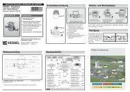
2. Einbau2.3 Einbauvorschlag Version „G“Abbildung zeigt NS 0,252.4 Maßzeichnung Version „G“ NS 0,5NS0,250,51LW400400800DN5050100l57012001630b5205201020V Fett [l]102040V Schlammfang [l]2550100h1 Ablauf [mm]525525457h2 Einlauf575575507h700700960Gewicht ca. [kg]918657
2. Einbau2.5 Einbauvorschlag Version „D“EntlüftungFettabscheiderAbbildung zeigt NS 22.6 Maßzeichnung Version „D“ NS 1 / 2Nenngröße12DN100100a10551355b10201300b112001500h110201136h211201236h3650750h4690790h513951595AbwasserinhaltSchlammfang Abscheider160 l 290 l315 l 550 lGewicht ca. kg110 kg160 kg8
3. Inbetriebnahme3.1 Anlage in Betriebsbereitschaft setzenDie Anlage ist vor der Zuführung von fetthaltigem Abwasser➤ vollständig zu reinigen' (einschließlich Zu- und Abläufe); Fest- und Grobstoffesind zu entfernen.➤ Die gereinigte Anlage ist bis zum Anlagenüberlauf mitkaltem Wasser zu füllen (dies entfällt natürlich, wenndie Behälter vorher dichtgeprüft wurden und das Wassernicht abgepumpt wurde).3.2 Einweisung / ÜbergabeDie Inbetriebnahme und Einweisung wird in der Regel vonei nem Installateur durchgeführt, kann aber auch aufWunsch gegen Berechnung von einem <strong>KESSEL</strong>-Beauftragtendurchgeführt werden.1. Folgende Personen sollten bei der Übergabe anwesendsein:➤ Abnahmeberechtigter des Bauherrn➤ SanitärinstallateurFerner empfehlen wir die Teilnahme des➤ Bedienungspersonals➤ Entsorgungsunternehmens2. Vorbereitung einer Einweisung und Übergabe:➤ Sanitärinstallationen müssen durchgeführt sein➤ betriebsbereite Wasserfüllung der Anlage (siehe Punkt3.1)3. Einweisung:➤ Kontrolle der Anlage auf Dichtheit, Transport- und Montageschädensowie Prüfung der Leitungsverbindungen➤ Information zur Entleerung (Absaugung)➤ Praktische Vorführung der Bedienungsmöglichkeiten4. Übergabe der Einbau- und Bedienungsanleitung5. Erstellung des Übergabeprotokolls.Nach Beendigung der Einweisung ist die Anlage wieder inbetriebsbereiten Zustand zu setzen.3.3 Übergabeprotokoll(siehe Seite 12)3.4 EntsorgungBei Version G muß das Fett täglich abgeschöpt werdenEntleerungsintervalle:Die Fettabscheideranlagen sind wöchentlich zu entleerenund zu reinigen.Achtung: Nur eine rechtzeitige Entsorgung der Anlagege währleistet eine richtige Funktion.Bei Version D ist die erste Entsorgung innerhalb von 2-3Wochen durchführen.Entleerungsintervalle:Gemäß DIN 4040 je nach Anfall 14-tägig, mindestensjedoch einmal pro Monat zu entleeren, wobei das Fettschichtfassungsvermögender Anlage der Norm entsprechend160 mm beträgt.Achtung: Nur eine rechtzeitige Entsorgung der Anlagegewährleistet eine richtige Funktion.Deshalb sollte mit einem fachkundigen Unternehmen eineEntsorgungsvertrag abgeschlossen werden. Die Entsorgungsarbeitensind möglichst während der Zeiten durchzuführen,in denen der Betrieb ruht. Bei geöffnetem Abscheidebehälterist mit einer Geruchsbelästigung zu rechnen.Durchführung der Entsorgung➤ Spannring lösen und Deckel abnehmen➤ Behälterwände reinigen, Fettreste entsorgen➤ Behälter mit Wasser vollfüllen➤ Deckeldichtung säubern und prüfen (falls notwendigerneuern)➤ Deckel mit Spannring verschließenEine Nachrüstung von Zubehör ist in der Regel möglich. Wirbitten Sie, dazu Ihre Anfrage an unsere Verkaufsabteilung zurichten.4. Zubehör9
5. Wartung und Überprüfung (Generalinspektion)Das Kapitel Sicherheitshinweise ist zu beachten!8.1 Wartung● Die Abscheideranlage ist jährlich durch einen Sachkundigen1) zu warten.Neben den Maßnahmen der Entsorgung sind dabei folgendeArbeiten durchzuführen:- Kontrolle der Innenwandflächen des Schlammfanges unddes Fettabscheiders,- Funktionskontrolle der elektrischen Einrichtungen undInstallationen, sofern vorhanden.- Die Feststellungen und durchgeführten Arbeiten sind imBetriebstagebuch zu erfassen und zu bewerten.● Sofern vorhanden, sind die elektromechanischen Baugruppen,wie Pumpen, Ventile, Absperrorgane usw. zweimalim Jahr nach den Herstellerangaben zu warten.8.2 Überprüfung (Generalinspektion)Vor der Inbetriebnahme und danach in regelmäßigenAbständen von nicht länger als 5 Jahren ist die Abscheideranlage,nach vorheriger vollständiger Entleerung und Reinigung,durch einen Fachkundigen 2) auf ihren ordnungsgemäßenZustand und sachgemäßen Betrieb zu prüfen.Es müssen dabei mindestens folgende Punkte geprüft bzw.erfasst werden:- Bemessung der Abscheideranlage- baulicher Zustand und Dichtheit der Abscheideranlage- Zustand der Innenwandflächen der Einbauteile und derelektrischen Einrichtungen, falls vorhanden- Ausführung der Zulaufleitung der Abscheideranlage alsLüftungsleitung über Dach- Vollständigkeit und Plausibilität der Aufzeichnungen imBetriebstagebuch- Nachweis der ordnungsgemäßen Entsorgung der entnommenenInhaltsstoffe der Abscheideranlage- Vorhandensein und Vollständigkeit erforderlicher Zulassungenund Unterlagen (Genehmigungen, Entwässerungspläne,Bedienungs- und WartungsanleitungenÜber die durchgeführte Überprüfung ist ein Prüfberichtunter Angabe eventueller Mängel zu erstellen. WurdenMängel festgestellt, sind diese unverzüglich zu beseitigen.1) Als „sachkundig“ werden Personen des Betreibers oderbeauftragter Dritter angesehen, die auf Grund ihrer Ausbildung,ihrer Kenntnisse und ihrer durch praktische Tätigkeitgewonnenen Erfahrungen sicherstellen, dass sie Bewertungenoder Prüfungen im jeweiligen Sachgebiet sachgerechtdurchführen.Die sachkundige Person kann die Sachkunde für Betriebund Wartung von Abscheideranlagen auf einem Lehrgangmit nachfolgender Vororteinweisung erwerben, den z. B. dieeinschlägigen Hersteller, Berufsverbände, Handwerkskammernsowie die auf dem Gebiet der Abscheidertechnik tätigenSachverständigenorganisationen anbieten.2) Fachkundige Personen sind Mitarbeiter betreiberunabhängigerBetriebe, Sachverständige oder sonstige Institutionen,die nachweislich über die erforderlichen Fachkenntnissefür Betrieb, Wartung und Überprüfung von Abscheideranlagenverfügen. Im Einzelfall können diese Prüfungenbei größeren Betriebseinheiten auch von intern unabhängigen,bezüglich ihres Aufgabengebietes nicht weisungsgebundenenenFachkundigen des Betreibers mit gleicherQualifikation und gerätetechnischer Ausstattung durchgeführtwerden.ArtikelBest.Nr.Generalinspektion Fettabscheider 917 411Betriebstagebuch Fettabscheider 917 409Dichtheit der Rohrstränge 917 41710
6. Gewährleistung1. Ist eine Lieferung oder Leistung mangelhaft, so hat <strong>KESSEL</strong>nach Ihrer Wahl den Mangel durch Nachbesserung zu beseitigenoder eine mangelfreie Sache zu liefern. Schlägt die Nachbesserungzweimal fehl oder ist sie wirtschaftlich nicht vertretbar,so hat der Käufer/Auftraggeber das Recht, vom Vertragzurückzutreten oder seine Zahlungspflicht entsprechend zumindern. Die Feststellung von offensichtlichen Mängeln mussunverzüglich, bei nicht erkennbaren oder verdeckten Mängelnunverzüglich nach ihrer Erkennbarkeit schriftlich mitgeteilt werden.Für Nachbesserungen und Nachlieferungen haftet KES-SEL in gleichem Umfang wie für den ursprünglichen Vertragsgegenstand.Für Neulieferungen beginnt die Gewährleis-tungsfristneu zu laufen, jedoch nur im Umfang der Neulieferung.Es wird nur für neu hergestellte Sachen eine Gewährleistungübernommen.Die Gewährleistungsfrist beträgt 24 Monate ab Auslieferung anunseren Vertragspartner.§ 377 HGB findet weiterhin Anwendung.Über die gesetzliche Regelung hinaus erhöht die <strong>KESSEL</strong> AGdie Gewährleistungsfrist für Leichtflüssigkeitsabscheider, Fettabscheider,Schächte, Kleinkläranlagen und Regenwasserzisternenauf 20 Jahre bezüglich Behälter. Dies bezieht sich aufdie Dichtheit, Gebrauchstauglichkeit und statische Sicherheit.Voraussetzung hierfür ist eine fachmännische Montage sowieein bestimmungsgemäßer Betrieb entsprechend den aktuellgültigen Einbau- und Bedienungsanleitungen und den gültigenNormen.2. <strong>KESSEL</strong> stellt ausdrücklich klar, dass Verschleiß kein Mangelist. Gleiches gilt für Fehler, die aufgrund mangelhafter Wartungauftreten.Hinweis: Das Öffnen von versiegelten Komponenten oder Verschraubungendarf nur durch den Hersteller erfolgen. Andernfallskönnen Gewährleistungsansprüche ausgeschlossen sein.Stand 01. 06. 201011
Anlagenpaß / WerksabnahmeMat. Bez.Mat.Nr./Auftr.-Nr./Fert. DatumRev.Std./Werkstoff/GewichtNorm/ZulasssungMaßeVolumenDichteBezeichnung 1Bezeichnung 2Die Anlage wurde vor Verlassen des Werks auf Vollständigkeit und Dichtheit überprüft.Datum Name des Prüfers12
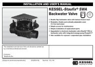
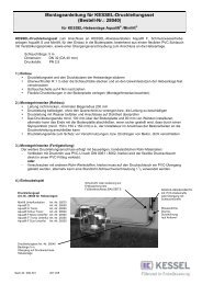
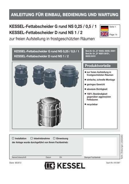
INSTALLATION AND OPERATING INSTRUCTIONS<strong>KESSEL</strong>-Grease Separator G round NS 0,25 / 0,5 / 1<strong>KESSEL</strong>-Grease Separator D round NS 1 / 2for free-standing set-up in frost-protected rooms<strong>KESSEL</strong>-Grease Separator G round NS 0,25 / 0,5 / 1<strong>KESSEL</strong>-Grease Separator D round NS 1 / 2Art.# „G“ 93025, 93050, 93001Art.# „D“ 98201.00/D1, 98202.00/D1Product advantagesfor free-standing set-up infrost-protected roomsQuick and easy assemblyCompact / lightAbsolutely airtight100% resistance againstaggressive greaseand soil acidsCan be recycledInstallation ServiceCommissioningThe installation and service of this unit should be carriedout by a licensed professional servicerCompany / Telephone number Date OrtStamp Companysubject to technical amendmentsEdition 08/2013Number 010-067EN
Safety InstructionsPersonnel used for installation, assembly, operation, maintenance and repair must havethe corresponding qualifications for such work. Areas of responsibility and the supervisionof personnel must be clearly specified by the operator.The operating safety of the system supplied is only ensured in the event of proper use.The limit values specified in the technical data must not be exceeded under any circumstances.Accident prevention regulations and the applicable standards and directives must beobserved at all times during installation, assembly, operation, maintenance and repair ofthe system!These include:• Accident prevention regulations- Construction work, BGV C22- Waste water systems, GUV-V C5• Safety regulations for work in enclosed areas of waste water systems, GUV-R 126• Handling of biological materials in waste water systems, GUV-R 145• Directives for work in tanks and restricted areas, BGR 117• Standards- Construction pits and ditches - Embankments, shoring, working area widths, DIN 4124- Laying and testing of waste water pipes and channels, DIN EN 1610• Work aids for safety and health protection in waste water systems.ACCESS:NO SMOKING! Smoking is strictly prohibited near or around the separator at all times !All sources of ignition or sparks are prohibited near or around the separator at all times !SLIPPERY WHEN WET! Take caution when standing / walking near the separator.During disposal, cleaning and maintenance the surrounding area can become extremelyslippery due to spilled oil / fuel.WARNING !• Dangers from gases and vapours such as the danger of suffocation,poisoning or explosion• Danger of falling• Danger of drowning• Fecal pollution in waste water containing faeces• High physical and psychic stresses of work in deep, restricted or dark areas• and othersFailure to observe these operating instructions may result in substantial material damage,physical injuries or fatal accidents.The system constitutes one component of an overall system. The operating instructionsof the overall system and the individual components must therefore also be observed.During all assembly, maintenance, inspection and repair to any of the components, theoverall system must be shut down and secured against restarting.Conversion or modifications to the system must only be made after consultation with themanufacturer. Original spare parts and accessories approved by the manufacturer mustbe used in order to ensure safety. The use of other parts may invalidate liability for theresulting consequences.15
Table of contentsSafety instructions ................................................................................. Page 151. General 1.1 Use............................................................................ Page 171.2 System description.................................................... Page 172. Installation 2.1 Installation and fitting ................................................ Page 172.2 Set-up ....................................................................... Page 182.3 Installation suggestion version “G”............................ Page 202.4 Dimensional drawing version “G” NS 0.5.................. Page 202.5 Installation suggestion version “D”............................ Page 212.6 Dimensional drawing version „D“ .............................. Page 213. Initial operation 3.1 Getting the system ready for operation..................... Page 223.2 Instruction / handover ............................................... Page 223.3 Handover certificate .................................................. Page 223.4 Entsorgung................................................................ Page 224. Accessories ............................................................................................... Page 225. Maintenance ............................................................................................... Page 236. Warranty ............................................................................................... Page 247. Separator charateristics ............................................................................................... Page 25DOP Declaration of performance ............................................................................................... Page 2616
1. General1.1 UseAnimal and vegetable oils and fats must not be dischargedinto public disposal systems and into bodies of water, sincethey can cause narrowing of cross-sections and blockagesin the disposal pipes when they set. In addition, fatty acidsare produced after a short decomposing time, leading tounpleasant odours and corroding pipes and constructionalelements of the draining systems. The solidified greaselayer on the surface of the water also hinders the necessaryoxygen supply to bodies of water and sewage treatmentplants.DIN EN 12056 requires harmful substances to be trapped.For these reasons, grease separator systems must be plannedwhich use corresponding means of disposal.Version „G“:This is a grease separator for mobile washing systemswhere the grease has to be skimmed off daily. Completeemptying and cleaning must be carried out once a week.Version „D“:Thanks to the direct disposal device, disposal from thegrease separator can take place with almost no odour pollution,since the system is sealed odour-proof and only hasto be opened for the subsequent check and for any cleaning.The hose from the disposal vehicle can be connected tothe permanently installed disposal pipe which is routed toan easily accessible spot (e.g. outside wall of building). Theseparated greases are drawn off directly into the disposalvehicle. This saves the time-consuming and unhygienicrouting of disposal hoses through usable and store rooms(e.g. food areas). In addition, there is no odour pollution.1.2 System descriptionThe <strong>KESSEL</strong> round grease separator systems of the versionsG and D of the nominal sizes 0.25 / 0.5 / 1 / 2 aremade up of the grease separator itself and an integratedsludge trap. Depending on the nominal size, the systemcomprises one or two tanks.The tanks and components are made of polyethylene (PE-HD). Thanks to the smooth, wax-like surface of the PE-HDmaterial, no additional coating is necessary. The systemcover hoods are made of polypropylene.Grease separator systems have been designed for freestandingset-up in buildings, i.e. in frost-free rooms.The technical data can be found on the system type plateand in the system pass on the last page of these operatinginstructions.2. Installation2.1 Installation and fittingThe <strong>KESSEL</strong> grease separator system is delivered readyfor operation. Each tank is packed separately on a pallet.Set-up material and accessories are included on the pallets,and can sometimes also be in the tanks.Please heed the instructions on the packaging! Examinethe system for transport damage before installation!During installation, the pertinent regulations in DIN 4040and EN 12056 must be heeded.1. The system must be set up horizontally on a level surfacein a frost-free room.2. Inlet and outlet pipes must be connected on site.3. A stilling section of at least 1 m in length with a gradient ofat least 1:50 must be upstream from drainpipes on theinlet side. The transition from the drainpipe to the stillingsection should be executed with two 45° bends (seeinstallation suggestion).This reduces➤ the danger of siphons and odour traps being suctioneddry➤ the oxygen added, and thus odour development➤ foam formation in the separator4. If the grease separator system is installed below thelocally specified backwater level, a lifting station must beinstalled downstream in accordance with DIN 1986 andDIN 4040, unless local regulations specify otherwise.5. In accordance with DIN 4040 Part 2, grease separatorsystems and their inlet and outlet pipes must be sufficientlyventilated and vented. This means the inlet pipemust be routed to above the roof as a ventilation pipe. Allconnection pipes longer than 5 m must be vented separately.If the inlet pipe is longer than 10 m and there is noseparately vented connection pipe available, the inletpipe must be equipped with an additional venting pipenear the separator.6. For cleaning purposes, we recommend the installation ofa hose with hot water connection in the room where thegrease separator is set up.7. DIN 1988, DVGW work sheet and local requirements ofthe authorities must be heeded when connecting the fillingand rinsing pipes.Connection with <strong>KESSEL</strong> filling device (included):- Fix the filling device in the filling and rinsing connectionscrews and using pipe brackets.- Bring the filling and rinsing pipes together and connectthem together to the R1 inner thread of the filling device.Connection with other separator systems- Filling and rinsing device to filling and rinsing connectionConnect (R 111/2 inner thread).17
2. Installation2.2 Set-upThe grease separator is screwed together when delivered.If it is not possible to move the system in the designatedroom in one piece, it can be dismantled.The individual parts are easy to transport and fit throughany standard door.The system is then set up again as follows.Grease separator version “G”, NS 0.25 / 0.5 / 11. Set up the base section and align horizontally.2. Insert the profile seal cleanly in the sealing groove. Lubricatethe upper half of the seal.3. Set the upper section onto the lower section.5. Check the correct fit of the profile seal and correct ifnecessary.4. Then tighten the screws cross-wise to fix the upper sectionto the lower section.5. The outlet must be inserted from the top through the openingin the cover. Then it is inserted through the previouslylubricated pipe duct seal from the inside.6. We recommend carrying out a leak test before the greaseseparator is connected up on site. For this purpose, thesystem should be set up where it is to be put into operation(making the pumping off of water after the test andfurther transport of the tank unnecessary). The tank is filledup to about 10 mm below the outlet with water andchecked for leaks. If water escapes, check the screwconnection first and tighten this if necessary. If this doesnot solve the problem, make sure the profiled seal is fittedcorrectly, check for soiling or damage and replace ifnecessary.7. Grease the seal and insert it into the groove of the coverattachment. Fit the cover and fix in place with the aid ofthe clamping ring.8. Connect the inlet and outlet of the grease separatorsystem.Grease separator version “D”, NS 1 / 21. Set up the base section and align horizontally (seeFigure 1).2. Insert the profile seal cleanly into the seal groove. Lubricatethe upper half of the seal. There is a spare sealincluded in case the seal gets damage during dismantling(see Figure 2).3. Set the upper section onto the lower section. Make surethat the partition wall in the upper section of the tank correspondsto the partition wall in the lower section (seeFig. 3). Check the correct fit of the profile seal and correctif necessary.4. Then screw the upper section to the lower section crosswiseas shown (see Fig. 4a/b/c).5. The submersible pipe must be inserted through the openingin the cover and fitted into the bracket on the basesection. Then it is pushed onto the lubricated drain pipefrom the inside (see Fig. 5).6. Connect the bottom riser pipe using a clamping muff andfix in place using the two pipe clamps as shown (see Fig.7). Care must be taken that the loose flange is betweenthe connection collar of the riser pipe and the upper pipeclamp. Connect the disposal flange to the disposal piperouted on site. (Flange connection DN 65, PN 10, DIN2501, hole pattern 145 mm).At the end of the disposal pipe, the Storz-B coupling (R 21/2" inner thread) must be mounted in a position easilyaccessible for the disposal vehicle. Any compensatorsnecessary to prevent sound transmission must be insertedin the disposal pipe.7. We recommend carrying out a leak test before the greaseseparator is connected up on site. For this purpose, thesystem should be set up where it is to be put into operation(making the pumping off of water after the test andfurther transport of the tank unnecessary). The tank is filledup to about 10 mm below the outlet with water andchecked for leaks. If water escapes, check the screwconnection first and tighten this if necessary. If this doesnot solve the problem, make sure the profiled seal is fittedcorrectly, check for soiling or damage and replace ifnecessary.8. Grease the seal and insert it into the groove of the coverattachment. Fit the cover and fix in place with the aid ofthe clamping ring (see Fig. 6).9. Connect the inlet and outlet of the grease separatorsystem.18
2. InstallationFigure shows Version „D“19
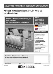
2. Installation2.3 Installation suggestion version “G”Figure shows NS 0,252.4 Dimensional drawing version “G” NS 0.5NS0,250,51LW400400800DN5050100l57012001630b5205201020V Grease [l]102040V Sludge trap [l]2550100h1 Outlet[mm]525525457h2 Inlet575575507h700700960Weight approx. [kg]9186520
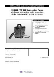
2. Installation2.5 Installation suggestion version “D”Venting thegrease separatorInletVenting via the roofConnectionfor disposalvehiclePavementSewer connection➀ <strong>KESSEL</strong> Grease SeparatorD NS 2➁ Sampling equipment➂ Filling equipment forflushing/filling connection➃ Shut-off valve➄ Water connection➅ Disposal pipe➆ A backwater flap mustbe planned for disposalvehicles withoutreflux protection➇ Storz-B coupling➈ “Universal” basementdrain with backwatervalve➉ Dirt trap Solenoid valve Lifting stationfigure shows NS 22.6 Dimensional drawing version „D“ NS 1 / 2➀ Inlet➁ Outlet➂ Sludge trap➃ Separating chamber➄ Cover with snapclosure➅ Disposal connectionNominalSize12DN100100a10551355b10201300b112001500h110201136h211201236h3650750h4690790h513951595Waste water contentsSludge trap Separator160 l 290 l315 l 550 lWeight appr. kg110 kg160 kg21
3. Initial operation3.1 Getting the system ready for operationBefore greasy waste water is filled into the system➤ it must be cleaned completely (including inlets and outlets);solids and coarse materials must be removed.➤ The cleaned system must be filled with cold water up tothe overflow (this is not relevant, of course, if the tankshave been checked for airtightness and the water hasnot been pumped out).3.2 Instruction / handoverInitial operation and instruction are generally carried out by afitter, but they can also be carried out by someone sent by<strong>KESSEL</strong> on request and for an extra charge.1. The following persons should be present for the handover:➤ Person authorised to perform the acceptance on behalfof the building owner➤ Sanitary fitterIn addition, we recommend the participation of➤ Operating staff➤ Disposal company2. Preparation of instruction and handover:➤ Sanitary installations must have been completed➤ The system must be ready to be filled with water (seesection 3.1)3. Instruction:➤ Check the system for airtightness, transport and installationdamage and check the pipe connections➤ Information about emptying (extraction)➤ Practical demonstration of the operating possibilities4. Handover of installation and operating instructionsOnce the instruction has been completed, the system mustbe made ready for operation again.3.3 Handover certificate(see page 12)3.4 DisposalWith version G, the grease must be skimmed off daily.Emptying intervals:Grease separator systems must be emptied and cleanedonce a week.Caution: Correct function can only be guaranteed if thesystem content is disposed of in good time.With version D, initial disposal must be carried out within 2-3 weeks.Emptying intervals:According to DIN 4040, grease separators must be emptieddepending on quantities every 14 days, but at least onceper month, whereby the grease layer capacity of the systemis 160 mm in compliance with the standard.Caution: Correct function can only be guaranteed if thesystem content is disposed of in good time.A disposal contract should therefore be concluded with aprofessional company. If possible, disposal work should becarried out outside business hours. When the separatortank is opened, odour pollution must be expected.Performing the disposal➤ Loosen the clamping ring and take the cover off➤ Clean the tank walls, dispose of residue grease➤ Fill tanks with water➤ Clean and check cover seal (renew if necessary)➤ Close the cover with the clamping ring5. Drawing up the handover certificate.Accessories can usually be retrofitted. Please address anyqueries you may have to our sales department4. Accessories22
5. MaintenanceThe chapter "Safety instructions" must be heeded!5.1 Servicing● The separator system must be serviced once a year by aqualified person 1)Alongside disposal measures, the following jobs mustbe carried out:- Check on the inner walls of the sludge trap and thegrease separator- Functional check on the electrical devices and installations,as appropriate.- Records of the findings and work carried out must bekept in the operating log and evaluated.● If present, the electro-mechanical assemblies such aspumps, valves, shut-off devices etc. must be servicedaccording to the manufacturer’s instructions twice ayear.5.2 Review (general inspection)Before initial operation and then at regular intervals of notlonger than 5 years, the separator system must be checkedfor proper condition and correct operation by a technicalexpert following complete emptying and cleaning. Atleast the following points must be checked and recorded:- Dimensioning of the separator system- State of repair and airtightness of the separator system- Condition of the inner walls of the built-in componentsand electrical devices, if appropriate- Completeness and plausibility of records in the operatinglog- Proof of correct disposal of the contents of the separatorsystem removed- Existence and completeness of the required permits anddocuments (approvals, plan sewer system, operating andservicing instructions)A test report must be drawn up for the inspection carriedout, listing any faults found. If faults are found, they have tobe eliminated without delay.1) The term “qualified” is used to describe employees at theoperators or from third parties who, on account of theirtraining, knowledge and practical experience, can guaranteethat they carry out evaluations or tests in a professionalway in the respective field.The qualified person can gain the knowledge requiredfor operating and servicing separator systems at a trainingcourse with subsequent on-site instruction, such asis offered by respective manufacturers, professionalassociations, chambers of industry and expert organisationsin the field of separator engineering.2) Technical experts are the employees of operator-independentcompanies, experts or other institutions whohave certified specialist knowledge about the operation,servicing and checking of separator systems. In individualcases, these tests can be carried out in larger companyunits by internal experts belonging to the operatorswho are independent with regard to their area of responsibilityand not bound by instructions, providing theyhave the same qualification and technical equipmentavailable.23
6. Warranty1. In the case that a <strong>KESSEL</strong> product is defective, <strong>KESSEL</strong>has the option of repairing or replacing the product. If theproduct remains defective after the second attempt torepair or replace the product or it is economically unfeasibleto repair or replace the product, the customer has the rightto cancel the order / contract or reduce payment accordingly.<strong>KESSEL</strong> must be notified immediately in writing ofdefects in a product. In the case that the defect is not visibleor difficult to detect, <strong>KESSEL</strong> must be notified immediatelyin writing of the defect as soon as it is discovered. If theproduct is repaired or replaced, the newly repaired or replacedproduct shall receive a new warranty identical to thatwhich the original (defective) product was granted. The termdefective product refers only to the product or part needingrepair or replacement and not necessarily to the entire productor unit. <strong>KESSEL</strong> products are warranted for a period of24 month. This warranty period begins on the day the productis shipped form <strong>KESSEL</strong> to its customer. The warrantyonly applies to newly manufactured products. Additionalinformation can be found in section 377 of the HGB.In addition to the standard warranty, <strong>KESSEL</strong> offers anadditional 20 year warranty on the polymer bodies of class I/ II fuel separators, grease separators, inspection chambers,wastewater treatment systems and rainwater storage tanks.This additional warranty applies to the watertightness, usabilityand structural soundness of the product.A requirement of this additional warranty is that the productis properly installed and operated in accordance with thevalid installation and user's manual as well as the correspondingnorms / regulations.2. Wear and tear on a product will not be considered a defect.Problems with products resulting from improper installation,handling or maintenance will also be considered a defect.Note: Only the manufacturer may open sealed componentsor screw connections. Otherwise, the warranty may becomenull and void01.06.201024
Separator characteristicsMat.-DescriptionMat.-No./Order-No./Prod. DateRef.No./Material/WeightEN/ApprovalDimensionsVolumeDensityDescription 1Description 2This unit has been checked for watertightness to be sure that it is fully operational before leaving the factory.Date Name of examiner25 16
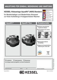
Leading in Drainage6 4Private homes withoutpublic sewage connection1 2 3 4 5Public buildings(e.g. hospital)1 2 3 4 5Public buildings(e.g. leisure facility)1 2 3 4 5Commercial buildings(e.g. hotel)4 5Commercial buildings(e.g. industrial / manufacturingfacilities)2 3 5Commercial buildings(e.g. gas/petrol station)1 2 3 4Private homes/multifamilyapartments/flats1 Backwater valves 2 Wastewater Lifting system 3 Lifting stations4 Drains and Channels 5 Separators 6 Septic Systems