ANLEITUNG FÃR EINBAU, BEDIENUNG UND WARTUNG KESSEL ...
ANLEITUNG FÃR EINBAU, BEDIENUNG UND WARTUNG KESSEL ...
ANLEITUNG FÃR EINBAU, BEDIENUNG UND WARTUNG KESSEL ...

You also want an ePaper? Increase the reach of your titles
YUMPU automatically turns print PDFs into web optimized ePapers that Google loves.
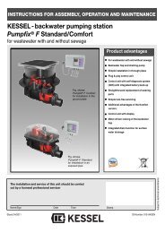
2. Installation2.2 Set-upThe grease separator is screwed together when delivered.If it is not possible to move the system in the designatedroom in one piece, it can be dismantled.The individual parts are easy to transport and fit throughany standard door.The system is then set up again as follows.Grease separator version “G”, NS 0.25 / 0.5 / 11. Set up the base section and align horizontally.2. Insert the profile seal cleanly in the sealing groove. Lubricatethe upper half of the seal.3. Set the upper section onto the lower section.5. Check the correct fit of the profile seal and correct ifnecessary.4. Then tighten the screws cross-wise to fix the upper sectionto the lower section.5. The outlet must be inserted from the top through the openingin the cover. Then it is inserted through the previouslylubricated pipe duct seal from the inside.6. We recommend carrying out a leak test before the greaseseparator is connected up on site. For this purpose, thesystem should be set up where it is to be put into operation(making the pumping off of water after the test andfurther transport of the tank unnecessary). The tank is filledup to about 10 mm below the outlet with water andchecked for leaks. If water escapes, check the screwconnection first and tighten this if necessary. If this doesnot solve the problem, make sure the profiled seal is fittedcorrectly, check for soiling or damage and replace ifnecessary.7. Grease the seal and insert it into the groove of the coverattachment. Fit the cover and fix in place with the aid ofthe clamping ring.8. Connect the inlet and outlet of the grease separatorsystem.Grease separator version “D”, NS 1 / 21. Set up the base section and align horizontally (seeFigure 1).2. Insert the profile seal cleanly into the seal groove. Lubricatethe upper half of the seal. There is a spare sealincluded in case the seal gets damage during dismantling(see Figure 2).3. Set the upper section onto the lower section. Make surethat the partition wall in the upper section of the tank correspondsto the partition wall in the lower section (seeFig. 3). Check the correct fit of the profile seal and correctif necessary.4. Then screw the upper section to the lower section crosswiseas shown (see Fig. 4a/b/c).5. The submersible pipe must be inserted through the openingin the cover and fitted into the bracket on the basesection. Then it is pushed onto the lubricated drain pipefrom the inside (see Fig. 5).6. Connect the bottom riser pipe using a clamping muff andfix in place using the two pipe clamps as shown (see Fig.7). Care must be taken that the loose flange is betweenthe connection collar of the riser pipe and the upper pipeclamp. Connect the disposal flange to the disposal piperouted on site. (Flange connection DN 65, PN 10, DIN2501, hole pattern 145 mm).At the end of the disposal pipe, the Storz-B coupling (R 21/2" inner thread) must be mounted in a position easilyaccessible for the disposal vehicle. Any compensatorsnecessary to prevent sound transmission must be insertedin the disposal pipe.7. We recommend carrying out a leak test before the greaseseparator is connected up on site. For this purpose, thesystem should be set up where it is to be put into operation(making the pumping off of water after the test andfurther transport of the tank unnecessary). The tank is filledup to about 10 mm below the outlet with water andchecked for leaks. If water escapes, check the screwconnection first and tighten this if necessary. If this doesnot solve the problem, make sure the profiled seal is fittedcorrectly, check for soiling or damage and replace ifnecessary.8. Grease the seal and insert it into the groove of the coverattachment. Fit the cover and fix in place with the aid ofthe clamping ring (see Fig. 6).9. Connect the inlet and outlet of the grease separatorsystem.18