ANLEITUNG FÃR EINBAU, BEDIENUNG UND WARTUNG KESSEL ...
ANLEITUNG FÃR EINBAU, BEDIENUNG UND WARTUNG KESSEL ...
ANLEITUNG FÃR EINBAU, BEDIENUNG UND WARTUNG KESSEL ...

You also want an ePaper? Increase the reach of your titles
YUMPU automatically turns print PDFs into web optimized ePapers that Google loves.
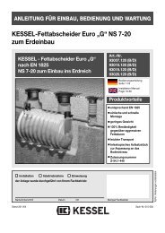
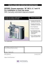
1. General1.1 UseAnimal and vegetable oils and fats must not be dischargedinto public disposal systems and into bodies of water, sincethey can cause narrowing of cross-sections and blockagesin the disposal pipes when they set. In addition, fatty acidsare produced after a short decomposing time, leading tounpleasant odours and corroding pipes and constructionalelements of the draining systems. The solidified greaselayer on the surface of the water also hinders the necessaryoxygen supply to bodies of water and sewage treatmentplants.DIN EN 12056 requires harmful substances to be trapped.For these reasons, grease separator systems must be plannedwhich use corresponding means of disposal.Version „G“:This is a grease separator for mobile washing systemswhere the grease has to be skimmed off daily. Completeemptying and cleaning must be carried out once a week.Version „D“:Thanks to the direct disposal device, disposal from thegrease separator can take place with almost no odour pollution,since the system is sealed odour-proof and only hasto be opened for the subsequent check and for any cleaning.The hose from the disposal vehicle can be connected tothe permanently installed disposal pipe which is routed toan easily accessible spot (e.g. outside wall of building). Theseparated greases are drawn off directly into the disposalvehicle. This saves the time-consuming and unhygienicrouting of disposal hoses through usable and store rooms(e.g. food areas). In addition, there is no odour pollution.1.2 System descriptionThe <strong>KESSEL</strong> round grease separator systems of the versionsG and D of the nominal sizes 0.25 / 0.5 / 1 / 2 aremade up of the grease separator itself and an integratedsludge trap. Depending on the nominal size, the systemcomprises one or two tanks.The tanks and components are made of polyethylene (PE-HD). Thanks to the smooth, wax-like surface of the PE-HDmaterial, no additional coating is necessary. The systemcover hoods are made of polypropylene.Grease separator systems have been designed for freestandingset-up in buildings, i.e. in frost-free rooms.The technical data can be found on the system type plateand in the system pass on the last page of these operatinginstructions.2. Installation2.1 Installation and fittingThe <strong>KESSEL</strong> grease separator system is delivered readyfor operation. Each tank is packed separately on a pallet.Set-up material and accessories are included on the pallets,and can sometimes also be in the tanks.Please heed the instructions on the packaging! Examinethe system for transport damage before installation!During installation, the pertinent regulations in DIN 4040and EN 12056 must be heeded.1. The system must be set up horizontally on a level surfacein a frost-free room.2. Inlet and outlet pipes must be connected on site.3. A stilling section of at least 1 m in length with a gradient ofat least 1:50 must be upstream from drainpipes on theinlet side. The transition from the drainpipe to the stillingsection should be executed with two 45° bends (seeinstallation suggestion).This reduces➤ the danger of siphons and odour traps being suctioneddry➤ the oxygen added, and thus odour development➤ foam formation in the separator4. If the grease separator system is installed below thelocally specified backwater level, a lifting station must beinstalled downstream in accordance with DIN 1986 andDIN 4040, unless local regulations specify otherwise.5. In accordance with DIN 4040 Part 2, grease separatorsystems and their inlet and outlet pipes must be sufficientlyventilated and vented. This means the inlet pipemust be routed to above the roof as a ventilation pipe. Allconnection pipes longer than 5 m must be vented separately.If the inlet pipe is longer than 10 m and there is noseparately vented connection pipe available, the inletpipe must be equipped with an additional venting pipenear the separator.6. For cleaning purposes, we recommend the installation ofa hose with hot water connection in the room where thegrease separator is set up.7. DIN 1988, DVGW work sheet and local requirements ofthe authorities must be heeded when connecting the fillingand rinsing pipes.Connection with <strong>KESSEL</strong> filling device (included):- Fix the filling device in the filling and rinsing connectionscrews and using pipe brackets.- Bring the filling and rinsing pipes together and connectthem together to the R1 inner thread of the filling device.Connection with other separator systems- Filling and rinsing device to filling and rinsing connectionConnect (R 111/2 inner thread).17