CLEAR-COM ECLIPSE I-SERIES INTERCOM PANELS INSTRUCTION MANUAL
I-Series Manual - Clear-Com
I-Series Manual - Clear-Com
- No tags were found...

Create successful ePaper yourself
Turn your PDF publications into a flip-book with our unique Google optimized e-Paper software.
<strong>CLEAR</strong>-<strong>COM</strong> <strong>ECLIPSE</strong>I-<strong>SERIES</strong> INTER<strong>COM</strong> <strong>PANELS</strong><strong>INSTRUCTION</strong> <strong>MANUAL</strong>
CONTENTSOPERATING AN I-<strong>SERIES</strong> INTER<strong>COM</strong> PANEL . . 1-1Features of i-Series Intercom Panels . . . . . . . . . . . . . . . . . . . . . . . . 1-1i-Series Construction . . . . . . . . . . . . . . . . . . . . . . . . . . . . . . . . . . . . 1-2i-Series Module Descriptions . . . . . . . . . . . . . . . . . . . . . . . . . . . . . . 1-2Key Module . . . . . . . . . . . . . . . . . . . . . . . . . . . . . . . . . . . . . . . . . . 1-2Function Key Module . . . . . . . . . . . . . . . . . . . . . . . . . . . . . . . . . . 1-4Mic-Headset Module . . . . . . . . . . . . . . . . . . . . . . . . . . . . . . . . . . . 1-5Level-Control Module . . . . . . . . . . . . . . . . . . . . . . . . . . . . . . . . . . 1-5AUX-101 Auxiliary Options Module. . . . . . . . . . . . . . . . . . . . . . . . 1-5Standard i-Series panel Configurations. . . . . . . . . . . . . . . . . . . . . 1-8Start-Up Sequences . . . . . . . . . . . . . . . . . . . . . . . . . . . . . . . . . . . . . 1-9Non-Display Key Module Start-Up Sequence . . . . . . . . . . . . . . . . 1-9Display Key Module Start-Up Sequence . . . . . . . . . . . . . . . . . . . . 1-9Function Key Module Start-Up Sequence . . . . . . . . . . . . . . . . . . 1-10Front Panel Controls and Lights . . . . . . . . . . . . . . . . . . . . . . . . . . . 1-10A Note About Terminology . . . . . . . . . . . . . . . . . . . . . . . . . . . . . 1-10About Displays . . . . . . . . . . . . . . . . . . . . . . . . . . . . . . . . . . . . . . 1-10About Keys . . . . . . . . . . . . . . . . . . . . . . . . . . . . . . . . . . . . . . . . . 1-11Temporary or Latched Action . . . . . . . . . . . . . . . . . . . . . . . . . 1-11Active and Non-Active Keys . . . . . . . . . . . . . . . . . . . . . . . . . . 1-11About Lights . . . . . . . . . . . . . . . . . . . . . . . . . . . . . . . . . . . . . . . . 1-12Call-Waiting Light. . . . . . . . . . . . . . . . . . . . . . . . . . . . . . . . . . . 1-12In-Use Light . . . . . . . . . . . . . . . . . . . . . . . . . . . . . . . . . . . . . . . 1-13Telephone Off-Hook Light . . . . . . . . . . . . . . . . . . . . . . . . . . . . 1-13Radio-Receiver Active Light . . . . . . . . . . . . . . . . . . . . . . . . . . 1-13Panel Connected Light . . . . . . . . . . . . . . . . . . . . . . . . . . . . . . 1-14Audio-Presence Light . . . . . . . . . . . . . . . . . . . . . . . . . . . . . . . 1-14Incompatible Firmware Light . . . . . . . . . . . . . . . . . . . . . . . . . . 1-14Summary of Key Module Lights . . . . . . . . . . . . . . . . . . . . . . . . . 1-14Answer-Back Feature . . . . . . . . . . . . . . . . . . . . . . . . . . . . . . . . . 1-15Answer-Back and Clear Keys . . . . . . . . . . . . . . . . . . . . . . . . . 1-15Answering a Call with the Answer-Back Key. . . . . . . . . . . . . . 1-16Answering a Second Call from the Answer-Back Stack . . . . . 1-17Summary of Answer-Back and Clear Key Lights . . . . . . . . . . . . 1-18Volume Controls . . . . . . . . . . . . . . . . . . . . . . . . . . . . . . . . . . . . . 1-18Speaker and Headset Volume Controls . . . . . . . . . . . . . . . . . 1-18Adjusting Listen Levels . . . . . . . . . . . . . . . . . . . . . . . . . . . . . . 1-19Clear-Com Communication SystemsI-Series Instruction Manuali
Resetting Listen Levels to the Default Level . . . . . . . . . . . . . . 1-21Panel Upgrade Facility (Eclipse V5.1 or later) . . . . . . . . . . . . . 1-22ACCESSING I-<strong>SERIES</strong> BASIC FUNCTIONS . . . . . 2-1Turning the Gooseneck Microphone On and Off. . . . . . . . . . . . . . 2-1Turning the Headset Microphone On and Off . . . . . . . . . . . . . . . . 2-2Turning the Speaker On and Off . . . . . . . . . . . . . . . . . . . . . . . . . . 2-2Using the “Listen” Key to Access Functions . . . . . . . . . . . . . . . . . 2-2Activating the “Monitor Mode” of a Talk-with-Listen Key . . . . . . 2-3Sending Call Signals . . . . . . . . . . . . . . . . . . . . . . . . . . . . . . . . . 2-4Releasing Remote Telephone Lines . . . . . . . . . . . . . . . . . . . . . 2-5Summary of Function Key Module Lights . . . . . . . . . . . . . . . . . . . 2-7ACCESSING I-<strong>SERIES</strong> ADVANCED FUNCTIONS 3-1Overview of Advanced Features . . . . . . . . . . . . . . . . . . . . . . . . . . 3-2Telephone Dialing from the Keypad (#1 Key) . . . . . . . . . . . . . . . . 3-2Accessing Local Exclusive (#2 Key) . . . . . . . . . . . . . . . . . . . . . . . 3-3Local Page Override (#3 Key). . . . . . . . . . . . . . . . . . . . . . . . . . . . 3-4IFB, Party Line and Fixed Group Assignments (#4 key) . . . . . . . . 3-4Setting Up IFB Sources and Destinations on an i-Series panel 3-5Setting Up Party Line members on an i-Series panel . . . . . . . . 3-5Setting Up Fixed Group members on an i-Series panel . . . . . . 3-6Local Key Assignment (#5 Key) . . . . . . . . . . . . . . . . . . . . . . . . . . 3-6Swap Page (#6 Key) . . . . . . . . . . . . . . . . . . . . . . . . . . . . . . . . . . 3-10Local Preferences (#7 Key). . . . . . . . . . . . . . . . . . . . . . . . . . . . . 3-10Listen Level Reset . . . . . . . . . . . . . . . . . . . . . . . . . . . . . . . . . . 3-11Gooseneck Microphone Volume Level . . . . . . . . . . . . . . . . . . 3-11Headset Microphone Volume Level. . . . . . . . . . . . . . . . . . . . . 3-12Sidetone Volume Level . . . . . . . . . . . . . . . . . . . . . . . . . . . . . . 3-12Exit. . . . . . . . . . . . . . . . . . . . . . . . . . . . . . . . . . . . . . . . . . . . . . 3-13Accessing Port Information (#9 Key). . . . . . . . . . . . . . . . . . . . . . 3-13Clearing the Current Programming . . . . . . . . . . . . . . . . . . . . . . . 3-13Escaping the Current Programming . . . . . . . . . . . . . . . . . . . . . . 3-13Entering the Current Programming . . . . . . . . . . . . . . . . . . . . . . . 3-14Adjusting Background Lighting . . . . . . . . . . . . . . . . . . . . . . . . . . 3-14Selecting a Feature from the Feature Menu . . . . . . . . . . . . . . . . 3-15CONNECTING TO AN <strong>ECLIPSE</strong> MATRIX, TO ACPOWER, AND TO AUDIO OPTIONS . . . . . . . . . . . 4-1Rear-Panel Modules . . . . . . . . . . . . . . . . . . . . . . . . . . . . . . . . . . . . . 4-1AC Power . . . . . . . . . . . . . . . . . . . . . . . . . . . . . . . . . . . . . . . . . . . 4-1iiClear-Com Communication SystemsI-Series Instruction Manual
SPECIFICATIONS . . . . . . . . . . . . . . . . . . . . . . . . . . 8-1GLOSSARY . . . . . . . . . . . . . . . . . . . . . . . . . . . . . . . 9-1Eclipse Manuals . . . . . . . . . . . . . . . . . . . . . . . . . . . . . . . . . . . . . . . . 9-5Software Manuals . . . . . . . . . . . . . . . . . . . . . . . . . . . . . . . . . . . . . 9-5Hardware Manuals . . . . . . . . . . . . . . . . . . . . . . . . . . . . . . . . . . . . 9-5LIMITED WARRANTY . . . . . . . . . . . . . . . . . . . . . . . W-ITECHNICAL SUPPORT & REPAIR POLICY. . . . . W-VTECHNICAL SUPPORT POLICY. . . . . . . . . . . . . . . . . . . . . . . . . . W-vRETURN MATERIAL AUTHORIZATION POLICY . . . . . . . . . . . . . W-viREPAIR POLICY . . . . . . . . . . . . . . . . . . . . . . . . . . . . . . . . . . . . . W-viiiivClear-Com Communication SystemsI-Series Instruction Manual
FIGURESFigure 1-1 Key Modules................................................................... 1-3Figure 1-2 Function Key Modules.................................................... 1-4Figure 1-3 Mic-Headset Module ...................................................... 1-5Figure 1-4 Level-Control Module ..................................................... 1-5Figure 1-5 The Eleven Front-Panel Modules................................... 1-7Figure 1-6 Standard Panels 1.......................................................... 1-8Figure 1-7 Standard Panels 2.......................................................... 1-9Figure 1-8 Key Module .................................................................. 1-10Figure 1-9 Answer-Back and Clear Keys....................................... 1-16Figure 1-10 Answering a Call from an Unassigned Source at the Answer-BackKey............................................................................... 1-17Figure 1-11 Main Volume and Program Volume Controls ............. 1-18Figure 1-12 Adjusting Listen Levels Method 1............................... 1-20Figure 1-13 Adjusting Listen Levels Method 2............................... 1-21Figure 2-1 Basic Function Keys....................................................... 2-1Figure 2-2 Accessing Features from the Listen Key........................ 2-3Figure 2-3 Activating the “Monitor Mode” of a Talk-with-Listen Key 2-4Figure 3-1 Features Accessed by Keys on the Numeric Keypad .... 3-1Figure 3-2 Telephone Dialing from the Function Keypad Module ... 3-3Figure 3-3 Assigning a Remote Destination to a Talk or Talk-with-ListenKey................................................................................................... 3-7Figure 3-4 Assigning a Remote Source to a Listen Key .................. 3-8Figure 3-5 Adjusting Local Preferences......................................... 3-10Figure 3-6 Submenu of Display Contrast Values........................... 3-14Figure 3-7 Submenu of Baud Rate Values .................................... 3-15Figure 3-8 Selecting a Feature from the Feature Menu................. 3-16Figure 4-1 Rear Panel of an i-Series Intercom Panel ...................... 4-1Figure 4-2 Communications Module Connectors ............................ 4-2Figure 4-3 Auxiliary Options Module Connectors ............................ 4-3Figure 4-4 i-Series panel Expansion Panel ................................... 4-12Figure 5-1 v-Station Expansion Panel ............................................. 5-1Figure 5-2 Two v-stations control and display listen levels for one i-Seriespanel ......................................................................................... 5-2Figure 5-3 Connecting two v-stations to an i-Series panel .............. 5-2Figure 5-4 A fully populated configuration of v-stations................... 5-4Figure 5-5 Connecting a fully populated configuration of v-stations 5-5Figure 6-1 Matrix Frame to Panel Wiring...................................... 6-2Figure 6-2 Expansion Out Connector Pinout Diagram .................... 6-4Figure 6-3 RJ-45 to Matrix Connector Pinout Diagram.................... 6-5Figure 6-4 General Purpose Inputs Connector Pinout Diagram ...... 6-6Figure 6-5 Relay Outputs Connector (J3) Pinout Diagram .............. 6-7Figure 6-6 Connector Pinout Diagrams for Speaker-Feed Output andLine-Level Output ............................................................................ 6-8Figure 6-7 Connector Pinout Diagrams for Hot Microphone Output (J8),Program Input (J9), and Auxiliary Microphone Input (J10) .............. 6-9Figure 7-1 Reset the panel if problems occur.................................. 7-1Clear-Com Communication SystemsI-Series Instruction Manuali
Figure 7-1 Analog Block Diagram.................................................... 7-5Figure 7-2 Panel Block Diagram...................................................... 7-6iiClear-Com Communication SystemsI-Series Instruction Manual
IMPORTANT SAFETY<strong>INSTRUCTION</strong>SFor your safety, it is important to read and follow theseinstructions before operating an i-series panel:(1) WARNING: To reduce the risk of fire or electric shock, do notexpose an i-Series panel to rain or moisture. Do not operate ani-Series panel near water, or place objects containing liquid on it. Donot expose an i-Series panel to splashing or dripping water.Please read and followthese instructionsbefore operating ani-Series panel.(2) For proper ventilation, make sure ventilation openings are notblocked. Install the i-Series panel according to the directions in theInstallation Chapter of this manual.(3) Do not install an i-Series panel near a heat source such as aradiator, heat register, stove, or other apparatus (including amplifiers)that produces heat. Do not place naked flame sources such as candleson or near an i-Series panel.(4) Do not defeat the safety purpose of the polarized or grounding-typeplug. A polarized plug has two blades, with one blade wider than theother. A grounding-type plug has two blades and a third groundingprong. The wide blade or the third prong is provided for your safety. Ifthe provided plug does not fit into your outlet, consult an electrician forreplacement of the obsolete outlet.(5) Protect the power plug from being walked on or pinched particularlyat plugs, convenience receptacles, and the point where they exit fromthe i-Series panel’s chassis.(6) Only use attachments/accessories specified by Clear-ComIntercom Systems.(7) Unplug the i-Series panel during lightning storms or when unusedfor long periods of time.(8) Refer all servicing to qualified service personnel. Servicing isrequired when:• The i-Series panel has been damaged in any way, such as whena power-supply cord or plug is damaged.• Liquid has been spilled or objects have fallen into the i-Seriespanel’s chassis.• The i-Series panel has been exposed to rain or moisture.• The i-Series panel does not operate normally.• The i-Series panel has been dropped.Please familiarize yourself with the safety symbols in Figure 1. Whenyou see these symbols on an i-Series panel, they warn you of thepotential danger of electric shock if the i-Series panel is usedClear-Com Communication SystemsI-Series Instruction Manualiii
improperly. They also refer you to important operating andmaintenance instructions in the manual.CAUTIONRISK OF ELECTRIC SHOCKDO NOT OPENThis symbol alerts you to the presence of uninsulated dangerousvoltage within the product's enclosure that might be of sufficientmagnitude to constitute a risk of electric shock. Do not openthe product's case.This symbol informs you that important operating and maintenanceinstructions are included in the literature accompanyingthis product.Figure 1: Safety SymbolsivClear-Com Communication SystemsI-Series Instruction Manual
1OPERATING ANI-<strong>SERIES</strong> INTER<strong>COM</strong>PANELClear-Com i-series intercompanels are designed withconfigurable front and backpanels.The i-series of intercom panels for the Eclipse matrix system representan innovative concept in intercom panel design. Each panel isconstructed from several individual units called modules, which can beadded or removed in the field, giving you exceptional flexibility inplanning a panel’s initial configuration and then easily changing theconfiguration as future operational needs change.FEATURES OF I-<strong>SERIES</strong> INTER<strong>COM</strong><strong>PANELS</strong>The i-series design emphasizes simplicity. No specialized training isrequired to operate an i-series panel. Intuitive lighting indicates thestatus of keys for ease of use. Each key may be programmed as eithera talk, a listen, or a talk-with-listen.Features of the i-Series panels include:• Available in a number of standard configurations with 8, 16 or 32keys.• Up to five expansion panels can be connected to an i-Seriespanel (E-1410E expansion panels) as described in chapter 5 ofthis manual.• Full graphic LED-backlit displays for each key on display panels.• 16-button keypad module for DTMF dialing and panelreprogramming (I-1430E and I-1470E only).• Individual listen level adjust on every panel.• Auto-sensing headset and microphone connectors.• Access to multiple audio sources and multiple speaker andheadset inputs and outputs when an auxiliary options module isinstalled (I-1470E only). The auxiliary options module alsoprovides you with two relays and two GPIs (general-purposeinputs) that can be used either locally or system-wide.• Advanced menu features allow you to assign new destinationsand sources to your panel directly from your panel, to programIFB sources and destinations, to dial telephone interfaces, totransform your panel into an assignment panel, to reset localvolume levels, and more.Clear-Com Communication SystemsI-Series Instruction Manual1-1
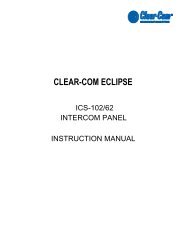
I-<strong>SERIES</strong> CONSTRUCTIONi-Series panels are sturdily constructed from the highest qualitycomponents. Each i-Series panel’s chassis is constructed ofcold-rolled steel. Front-panel modules and removable rack ears arecast from aluminum. All external connectors and switches are made ofthe highest quality components and are structurally reinforced.Keys feature long-life LED illumination. Displays are full-graphic LCDwith long-life LED backlighting.i-Series internal architecture is based on the widely used MotorolaM-Core processor. All audio is digitized by CODECs and routed to aDSP to be controlled as desired by the user.All i-series panels have internal power supplies.I-<strong>SERIES</strong> MODULE DESCRIPTIONSi-Series intercom panels are designed in standardized units calledmodules. Because the panels are designed this way, you can add orremove components, such as keys, in the field without replacing theentire intercom panel. Repairing panels is easier, faster, and lessexpensive. The following sections give you an overview of i-seriesmodules.KEY MODULEThe key module is the basic building block of an i-series intercompanel. A panel can accommodate from one to four key modules whichcan be added or removed as needed.Each key module has eight backlit keys that glow in either green or redto indicate their talk/listen status. Each key has a 5-characteralphanumeric display that shows its currently programmedassignment. The alphanumeric name of an assignment is typicallycalled a “label.”Display panels feature backlit LCD displays with labels that areupdated as you program them from the Eclipse Configuration System.Non-display panels have slots for paper labels. A display andnon-display key module are illustrated in Figure 1-1.1-2Clear-Com Communication SystemsI-Series Instruction Manual
Display Key Modulewith Electronic LabelsNon-Display Key Modulewith Printed Labels+Cams Phone IFB-1 IFB-2+Cams Dir IFB-3 PGM+Cams Phone IFB-1IFB-2+Cams Dir IFB-3 PgmFigure 1-1: Key ModulesClear-Com Communication SystemsI-Series Instruction Manual1-3
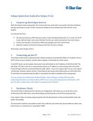
FUNCTION KEY MODULEThe function key module contains the intercom panel’s basic andadvanced controls. There are two types of function key modules in thei-series. The 16-key module has a numeric keypad while the 4-keymodule does not, as illustrated in Figure 1-2.The 4-key module contains the keys that control basic intercomfunctions such as switching between gooseneck/headset speakersand microphones, sending call signals, and adjusting listen levels. Ithas separate volume controls for intercom and program sources. Theoperation of this module is discussed later in the chapter.The 16-key module includes the basic function keys and adds a12-button numeric keypad for dialing telephone interfaces and forprogramming advanced features. Advanced features allow you to:• Temporarily deactivate all latched keys on a panel.• Override the on/off or volume settings at a destination.• Assign new sources and destinations to your panel from yourpanel.• Program IFB sources and destinations.• Reset microphone and sidetone volume levels.• Receive a variety of information about your panel on the panel’sLCD displays.These functions are described in detail later in this chapter.Function Key Module without KeypadFunction Key Module with KeypadGN MICMAINGN MIC1 2 ABC3 DEFMAINHS MICHS MIC4 GHI5 JKL6 MNOSPKR ONVOL / PROGSPKR ON7 PQRS8 TUV9 WXYZVOL / PROGLISTENLISTEN* RED0 CLR#GRNFigure 1-2: Function Key Modules1-4Clear-Com Communication SystemsI-Series Instruction Manual
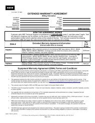
MIC-HEADSET MODULEEvery i-series intercom panel has a mic-headset module equipped withan auto-sensing headset and microphone connector and an integratedloudspeaker.Figure 1-3: Mic-Headset ModuleLEVEL-CONTROL MODULEThe level-control module is used in conjunction with a key module togive you a constant visual read-out of each key’s volume level (thisoption is no longer available for new sales but is supported).The auxiliary options moduleconnects your i-Series panelto a variety of audio andcontrol functions.Figure 1-4: Level-Control ModuleAUX-101 AUXILIARY OPTIONS MODULEThe auxiliary options module connects your i-Series panel to a varietyof audio and control inputs and outputs. It is an optional module thatcan be installed in the factory or in the field, depending on your needs.Located on the rear-panel of the i-Series panel’s chassis, it providesthe following functions:• General purpose inputs• Relay outputs• Speaker-feed output• Line-level output• Hot-microphone output• Balanced-program input• Auxiliary microphone inputClear-Com Communication SystemsI-Series Instruction Manual1-5
The auxiliary option module’s functions are described in detail later inthis chapter.1-6Clear-Com Communication SystemsI-Series Instruction Manual
KEY MODULES+Cams Phone IFB-1 IFB-2+Cams Dir IFB-3 PGM+Cams Phone IFB-1IFB-2+Cams Dir IFB-3 PgmDisplay Key ModuleNon-Display Key Module(No longer sold)Blank Key Module<strong>CLEAR</strong><strong>CLEAR</strong>Phone IFB-1 IFB-2Dir IFB-3 PGMPhone IFB-1IFB-2Dir IFB-3 PgmANSWRANSWRDisplay Key Modulewith Clear and Answer KeysNon-Display Key Modulewith Clear and Answer Keys(No longer available)FUNCTION KEY MODULESGN MIC1 2 ABC3 DEFMAINGN MICMAINHS MIC4 GHI5 JKL6 MNOHS MICSPKR ON7 PQRS8 TUV9 WXYZVOL / PROGSPKR ONVOL / PROGLISTEN* RED0 CLR#GRNFunction Key Module with KeypadLISTENFunction Key Module without KeypadBlank Function Key ModuleMIC-HEADSET MODULESLEVEL-CONTROL MODULEMic-Headset Module Blank Mic-Headset Module Level-Control Module(No longer available)Figure 1-5: The Eleven Front-Panel ModulesClear-Com Communication SystemsI-Series Instruction Manual1-7
STANDARD I-<strong>SERIES</strong> PANEL CONFIGURATIONSBelow are illustrations of the standard i-Series panels.i1430E Intercom Panel4 Display Key ModulesFunction Key Module with Keypadi1470E Intercom Panel4 Display Key ModulesFunction Key Module with KeypadAUX-101 module factory fittedi1110E Intercom Panel1 Display Key ModuleFunction Key Module without Keypadi1410E Intercom Panel4 Display Key ModulesFunction Key Module without KeypadFigure 1-6: Standard Panels 11-8Clear-Com Communication SystemsI-Series Instruction Manual
i1210E Intercom Panel2 Display Key ModulesFunction Key Module without Keypade1410E Key Expansion Panel4 Display Key ModulesFigure 1-7: Standard Panels 2The i-1470E panel is the same as the i-1430E panel with the additionof a AUX-101 option card fitted. The other main panels (but not theexpansion panels) may also have the AUX-101 option card fitted.START-UP SEQUENCESNON-DISPLAY KEY MODULE START-UP SEQUENCEWhen a panel with non-display key modules is connected to power, allkeys on each key module will flash red, then green, and will revert totheir programmed colors (red for talk or talk-with-listen; green forlisten). If there is no communication to the Eclipse matrix, the keys willflash red once per second until communication to the matrix isestablished.DISPLAY KEY MODULE START-UP SEQUENCEWhen a panel with display key modules is connected to power, each ofthe display modules will show the following message:Clear-ComVx.x.x@2000“V.x.x.x” represents the firmware version of the panel. All keys will flashred, then green, and will show their programmed colors and labels ifthere is communication to the matrix.Clear-Com Communication SystemsI-Series Instruction Manual1-9
If there is no communication to the matrix, the display will show themessage “No connection to Eclipse.” The keys will then flash red fourtimes per second until communication to the Eclipse matrix isestablished.FUNCTION KEY MODULE START-UP SEQUENCEWhen an intercom panel is connected to power, all of the keys on thefunction key module will flash red, then green, and will revert to theirprogrammed colors if there is communication to the matrix.If there is no communication to the matrix, the keys will be dark untilcommunication is established.FRONT PANEL CONTROLS AND LIGHTSA NOTE ABOUT TERMINOLOGYIn this manual, the term “source” refers to a device—intercom panel,interface, beltpack, or a variety of other devices—that sends audio toyour intercom panel. It represents a “listen” path to your panel. Theterm “destination” refers to a device to which you send audio. Itrepresents a “talk” path from your intercom panel.The names of these sources and destinations appear in the display ofyour intercom panel and are called “labels.” A label is a 5-characteralphanumeric name that identifies a source, destination, or controlfunction accessed by your intercom panel.ABOUT DISPLAYSThe 5-character name, or “label,” that you assign to a key is displayednext to the key on the key module (Figure 1-8). The labels on the upperrow refer to their corresponding upper-row keys and the labels on thelower row refer to their corresponding lower-row keys.KeysAlphanumeric KeyNames or "Labels"+Cams Phone IFB-1 IFB-2+Cams Dir IFB-3 PGMFigure 1-8: Key Module1-10Clear-Com Communication SystemsI-Series Instruction Manual
Display panels have full-graphic LED-backlit displays that you programfrom the Eclipse Configuration System. Non-display panels have metalgrooves into which paper labels can be inserted. Paper labels can beprinted from the Eclipse Configuration System.ABOUT KEYSEach key on any key module can be assigned as a talk, a listen, or atalk-with-listen from the Eclipse Configuration System. See the EclipseConfiguration System Manual for more information.Temporary or Latched ActionWhen you press a key to talk or listen, the key can be switched oneither temporarily or continuously.When you switch a key on temporarily, it is active for the particularperiod of time you require. Press and hold the key down for the desiredlength of time needed to talk or listen, then release the key to return itto its non-active state. You will only be able to talk or listen while youpress the key.Continuous or “latched” action allows you to lock a key into place, sothat you can talk or listen hands-free. Quickly tap a key to “latch” or“lock” it into place to talk or listen. The key will glow brightly to indicatethat it is active. The key will remain latched until you tap it again toreturn it to its non-active state.Active keys are bright red orgreen. Non-active keys aredim red or green. Keys thatare not assigned are off, withno illumination.Active and Non-Active KeysWhen you activate a key—that is, when you press or latch the key totalk or listen— the key becomes bright red or green. When you pressor latch an assigned talk key, the key lights up bright red while you talkto the destination. When you press or latch an assigned listen key, thekey lights up bright green while you listen to the source.Otherwise, a key that is not active—that is, a key that is not being usedto talk or listen— will be dimmed: dim red for a talk or talk-with-listenkey; dim green for a listen key.Table 1-1 shows the key colors associated with active or non-activetalk, listen, or talk-with-listen keys.Clear-Com Communication SystemsI-Series Instruction Manual1-11
KEY ACTIVE NON-ACTIVETALK A talk key glows brightred when you press orlatch the key to talk.A talk key glows dimred when it is notactive.LISTENTALK-WITH-LISTEN(<strong>COM</strong>BO)Setting up a combokey is described in theECS User Manualunder “PanelProgramming”.ABOUT LIGHTSTable 1-1: Key Colors for Active and Non-Active KeysA key can be programmed to light up in a variety of ways to indicate itsstatus. These options are discussed in the following sections. If youdecide to use one of these options, it must usually first be set up in theEclipse Configuration System. A table summarizing all of the lightoptions is located at the end of the section.Call-Waiting LightA listen key glows brightgreen when you press orlatch the key to listen.A talk-with-listen key(combo key) glowsbright red when youpress or latch the key totalk.When you activate a listen,the talk-with-listenkey will glow brightgreen.A listen key glowsdim green when it isnot active.If in talk mode, atalk-with-listen key(combo key) glowsdim red when notactive.There is nonon-active listenmode. A talk-with-listenkey alwaysreverts to non-activetalk.When a source calls an i-Series panel the ANSWR key will flash brightred at the call waiting rate (four times per second) and the source willbe displayed in the call waiting stack above the ANSWR key. If anyother key on the panel is assigned to the source this key will also flashat the call waiting rate. Audio from the source can be heard at thei-Series panel.When you press the ANSWR key (or another key assigned to thesource and flashing) to talk, the ANSWR key and any other keyassigned to the source stops flashing and becomes bright red toindicate that the call is active. When you release the key pressed totake the call it becomes dim red to indicate that it is not active as wellas any other key associated with the call.If a call is being answered when a second source calls you, theANSWR key will not flash at the call-waiting rate, but will continue toglow solidly bright red to indicate that it is active and the new call willbe added to the call waiting stack on the ANSWR key. If there is a keyon the i-Series panel assigned to the source of the new call this will1-12Clear-Com Communication SystemsI-Series Instruction Manual
flash bright red at the call rate. Audio from the stacked call will not beheard. Further calls will also be added to the answerback stack untilthe limit of eight calls is reached.To answer the second call the first call must be terminated by releasingthe key pressed to answer the first call. The first call will then becleared from the call waiting stack either on the expiry of theAnswerback Auto Clear timeout or when you press the <strong>CLEAR</strong> key.The ANSWR key will then flash at the call waiting rate to signal thenext call is waiting.The Answerback Auto Clear option sets the timeout before the currentcall is removed from the answer-back stack after the call has beenended. The Answerback Auto Clear timeout option is set up in theEclipse Configuration System (ECS) and it can be set to a valuebetween one and sixty seconds or set to off. See the EclipseConfiguration System Manual for more information.In-Use LightA key will double-flash once per second to indicate that a destinationyou are trying to call is in use.The in-use light is a feature that must be set up in the EclipseConfiguration System. For more information, see the EclipseConfiguration System Manual.Telephone Off-Hook LightA key will flash red once per second if a telephone interface isassigned to that key, and the telephone interface is off-hook. Thecentral matrix will cause each key assigned to the telephone interfaceon every panel in the system to flash at the off-hook rate whenever thetelephone interface is active (off-hook) at one or more of the panels.If you press or latch a key that is flashing at the telephone off-hookrate, the key will glow solidly bright red to indicate that the key is active.When you release the key, it will resume flashing at the telephoneoff-hook rate.The telephone off-hook light is set up by default in the EclipseConfiguration System. For more information, see the EclipseConfiguration System Manual.Radio-Receiver Active LightThe light on a key will flash red once per second if a radio receiver isassigned to that key, and the radio receiver is active. The centralmatrix will cause each key assigned to the radio receiver on everypanel in the system to flash at the radio-receiver active rate wheneverthe radio receiver is active at one or more of the panels.If you press or latch a key that is flashing at the radio-receiver activerate, the key will glow solidly red to indicate that the key is active.Clear-Com Communication SystemsI-Series Instruction Manual1-13
When you release the key, it will resume flashing at the radio-receiveractive rate.The radio-receiver active light requires that the radio receiver isconnected via a FOR-22 interface. The radio receiver active lightfeature must be enabled in the Eclipse Configuration System under theAdvanced Settings and Tallies options for the FOR-22 interface. Formore information, see the Eclipse Configuration System Manual.Panel Connected LightWhen the Station Connected Tally option is selected in the EclipseConfiguration System software (under Advanced Settings > GlobalSettings), whenever a destination panel is connected to the Matrixframe its assigned key on your panel will flash red once per second.This option is primarily used when a destination panel is connected tothe Matrix frame via a long-line link that might be active only at certaintimes.The Station Connected Tally is a feature that must be set up in theEclipse Configuration System program. For more information, see theEclipse Configuration System Manual.Audio-Presence LightIf you assign a source to your panel as a listen-only key, the key willflash green once per second if there is audio present at the source.The audio-presence light is a feature that must be set up in the EclipseConfiguration System. For more information, see the EclipseConfiguration System Manual.Incompatible Firmware LightIf the firmware on your panel is incompatible with the matrix, all lightson the panel will blink dim red once per second, and if displays arepresent, they will read: “No connection to Eclipse”.SUMMARY OF KEY MODULE LIGHTSTable 1-2 summarizes the meaning of key colors and blink rates on akey module.1-14Clear-Com Communication SystemsI-Series Instruction Manual
DISPLAY KEYS LED COLOR BLINK RATEKey programmed as listen-only dim green noneKey programmed as talk or dim red nonetalk-with-listenListen key active bright green noneTalk-with-listen key active bright red noneTalk-with-listen key listen-only bright green noneactiveCall Waiting bright red 4x per secondIn Use dim red 2x per secondAudio Presence dim green 1x per second(continued)Panel Connected dim red 1x per secondTelephone Off-Hook dim red 1x per secondRadio Receiver Active dim green 1x per secondIncompatible Firmware bright red 1x per secondTable 1-2: Key Colors and Blink RatesWith the answer-backfeature, you can reply toincoming calls from sourcesnot assigned to keys on yourpanel.ANSWER-BACK FEATUREWith the answer-back feature you can reply to incoming calls fromsources not assigned to keys on your intercom panel. You can also callout to destinations not assigned to keys on your panel.If a second unassigned source calls you while you are speaking to thefirst unassigned source, the second call will be placed in the“answer-back stack,” a group of up to eight waiting calls that areanswered in sequence.Note: All incoming calls can be answered at the answer-backkey—whether from sources with assigned keys on theintercom panel or from sources without assigned keys.Typically, however, only calls from sources withoutassigned keys are answered there.The following sections describe how to use the answer-back feature.You cannot latch an outgoingcall from the answer-backkey. This function ismomentary only.Answer-Back and Clear KeysThe answer-back key is the leftmost lower key on any intercom panel.The clear key is the leftmost upper key on any intercom panel. (SeeFigure 1-9). The keys are labeled “ANSWR” and “<strong>CLEAR</strong>.”Clear-Com Communication SystemsI-Series Instruction Manual1-15
Clear KeyClear KeyAnswer-Back KeyAnswer-Back KeyFigure 1-9: Answer-Back and Clear KeysAnswering a Call with the Answer-Back KeyWhen a source that is not assigned to a key on your panel calls you:When you press the ANSWRkey, you will talk to thedestination whose label is inthe display. To clear thedisplay, and talk to the nextcaller, press the <strong>CLEAR</strong> key.• The calling source’s label appears in the display above theANSWR key.• The ANSWR key flashes bright red to indicate a waiting call.These conditions will continue until you press the ANSWR key to talkor until the answer-back time-out period lapses and the call isautomatically removed from the answer-back stack.Note: The answer-back time-out period is set in the EclipseConfiguration System. It can be set to Off or between 10 and60 seconds. After the time-out period has elapsed, the callwill be removed and will no longer be available to answer.To answer a call from an unassigned source at the answer-backkey:1. Press and hold the ANSWR key to talk to the caller.When you press the ANSWR key, it becomes solid red to indicatethat it is active. Note that the ANSWR key cannot be latched; it is amomentary function.2. When you complete the call, release the ANSWR key.When you release the key, it becomes dim red to indicate that it isinactive.3. Press the <strong>CLEAR</strong> key to remove the caller’s label from the display.Note: The display clears automatically when the answer-backtime-out period elapses after you release the ANSWR key.Figure 1-10 illustrates the steps for answering a call from anunassigned source at the answer-back key.1-16Clear-Com Communication SystemsI-Series Instruction Manual
When you receive a call from a source not assigned to a key on your panel,the ANSWR key will flash red and the name of the source will appear in the display.2To end the call and clear the display for the next call, press <strong>CLEAR</strong>.1To answer, press and hold the ANSWR key.Figure 1-10: Answering a Call from an Unassigned Source at theAnswer-Back KeyAnswering a Second Call from the Answer-BackStackIf a second unassigned source calls you while you are talking to thefirst unassigned source:• The second caller’s audio will come through on your panel’sspeaker.• The second call will be placed in the “answer-back stack” (a calllist of up to eight possible waiting calls). The second caller’s labelwill appear directly above the current caller’s label. The currentcaller’s label appears in the display directly above the ANSWRkey.• The light on the ANSWR key will flash to show that a call iswaiting and that a call is currently in progress—by flashing at thecall-waiting rate to show that a call is waiting; but flashing brightred–dim red instead of the usual bright red–off to show that a callis also currently in progress.To answer a call waiting in the answer-back stack:1. Press and hold the ANSWR key to speak to the caller.The new caller’s label will appear in the position directly above theANSWR key, while the next waiting call (if there is one) will displayin the position directly above it. A total of eight calls can wait in theanswer-back stack. Only the two most recent caller’s labels willappear in the display above the ANSWR key.2. When you complete the call, release the ANSWR key.3. Press the <strong>CLEAR</strong> key to remove the caller’s label from the display.• The next unassigned caller’s label appears in the display abovethe ANSWR key.• The display clears automatically when the answer-back time-outperiod elapses after you release the ANSWR key.Clear-Com Communication SystemsI-Series Instruction Manual1-17
4. When the next caller’s label appears above the ANSWR key, pressthe ANSWR key to talk to the caller.5. Repeat steps 2 and 3 until all the calls in the answer-back stack areanswered.SUMMARY OF ANSWER-BACK AND <strong>CLEAR</strong> KEYLIGHTSTable 1-3 summarizes the meanings of the color and blink rates for theanswer-back and clear keys.ANSWER-BACK KEY KEY COLOR BLINK RATENo calls at answer-back off noneCall received atbright red 4x per secondanswer-backAnswer-back key pressed dim red noneClear key pressed off none<strong>CLEAR</strong> KEY KEY COLOR BLINK RATENo calls at answer-back off noneAnswer-back stack not dim green noneemptyClear key pressed bright green noneTable 1-3: Colors and Blink Rates for Answer-Back and Clear KeysThe volume program knob ismulti-functional. In addition toadjusting the programvolume, it adjusts listenlevels, scrolls through menuitems, and selects menuitems. These functions arediscussed later in thischapter.VOLUME CONTROLSSpeaker and Headset Volume ControlsAdjusting Intercom VolumeYou adjust the master intercom volume on your panel’s speaker andheadset with the main volume knob on the function key module, asshown in Figure 1-11. Turn the knob clockwise to increase the volume,counterclockwise to decrease it.GN MICHS MIC1 2 ABC4 GHI5JKL3DEF6 MNOMAINMain VolumeSPKR ONLISTEN7 PQRS* RED80TUVCLR9 WXYZ#GRNVOL / PROGProgram VolumeFigure 1-11: Main Volume and Program Volume Controls1-18Clear-Com Communication SystemsI-Series Instruction Manual
Adjusting Program Input VolumeThe VOL/PROG knoboperates in two ways. Yourotate the knob clockwise orcounterclockwise to adjustvolume levels or to scrollthrough menu items. Youpress the knob in, as if itwere a key, to select items ina menu.You receive program input at your panel through the auxiliary optionsmodule, so this module must be present before you can adjust theprogram input. If you do not have the auxiliary options module installedon your panel, the VOL/PROG knob on the function keypad will notoperate.You adjust the program input volume on your panel’s speaker andheadset with the program volume knob, labeled “VOL/PROG” on thefunction key module. Turn the knob clockwise to increase the volume,counterclockwise to decrease it.The six LEDs located to the left of the program volume knob indicatethe program volume level. As the volume goes up or down, the numberof LEDs that are illuminated changes. Minimum volume is indicated byone illuminated LED; maximum volume is indicated by six illuminatedLEDs.You control the brightness of the six-segment LED with the DisplayBrightness settings in the Eclipse Configuration System. Refer to theEclipse Configuration System Manual for more information.Note: You can also use the program volume knob to adjust listenlevels, to scroll through menu items, and to select menuitems. These functions are discussed later in this chapter.Adjusting Listen LevelsWhen you need to monitor several incoming sources at once, you canvary the volume of the sources by setting “listen levels.”For example, in a control room you may be listening simultaneously tothe lighting department, the sound department, and the tape editingdepartment, but because you need to cue the director when the showis ready to go on the air, listening to the tape editing department takeshighest priority. You need to adjust the volumes of the monitoredsources so that the tape editing department is louder than the others.To do this, you set listen levels.To adjust the listen level of an incoming source (Method 1):1. Press the desired listen key.The listen key becomes bright green.2. Press and release the VOL/PROG knob.The listen key becomes dim green and flashes.3. Press and release the listen key again.The listen key becomes bright green.4. Rotate the VOL/PROG knob either clockwise to increase thesource’s volume or counterclockwise to decrease the source’svolume.5. When the required volume has been reached, press and release theVOL/PROG knob to accept the setting.Clear-Com Communication SystemsI-Series Instruction Manual1-19
6. Press and release the listen key.The source’s volume is now set at the required level.Note: If you try to push an active listen path higher than themaximum possible volume, you will drive the volume of allother active paths downward, thus putting more emphasison the desired path.The VOL/PROG knoboperates in two ways. Yourotate the knob clockwise orcounterclockwise to adjustvolume levels or to scrollthrough menu items. Youpress the knob in, as if itwere a key, to select items ina menu.1 Press and release the desired listen key.2 Press and release the VOL/PROG knob.3 Press and release the listen key again.6 Press and release the listen key. The newvolume is now set.4 Rotate the VOL/PROG knob clockwise to increase thevolume, and counterclockwise to decrease it.5 When you reach the desired volume, press andrelease the VOL/PROG knob to accept the setting.Figure 1-12: Adjusting Listen Levels Method 1To adjust the listen level of an incoming source (Method 2):The listen level may also be adjusted using the Local Preferencesfacility (requires a 16-button key module).This method works only with a 16-button function key module.1. Press the ENTER key (labeled “#GRN”) on the numeric keypad todisplay a list of menu items.The first two menu items appear in the panel’s leftmost display. (Foran illustration of this procedure, see Figure 11.)2. Scroll to menu item number 7, “Local Preferences,” by rotating theVOL/PROG knob.You can also scroll through the menu items one at a time bypressing the <strong>CLEAR</strong> key to scroll up the menu and the ANSWR keyto scroll down the menu.3. Select item 7 by pressing the VOL/PROG knob in, as if it were a key,when item 7 appears in the display.• Another menu—a submenu—appears in the display.• You can also select item number 7 simply by pressing the 7 key onthe numeric keypad.4. Scroll though the submenu to item number 5, “Listen Level Adjust,”and select it by pressing the VOL/PROG knob in, as if it were a key.• The words “Listen Level” appear in the panel’s leftmost display toindicate that you are in listen-level-adjust mode.1-20Clear-Com Communication SystemsI-Series Instruction Manual
• You can also select submenu item number 5 simply by pressingthe 5 key on the numeric keypad.Note: To quickly enter listen-level-adjust mode, simply pressthree keys in quick succession: the ENTER key (labeled“#GRN”), followed by the 7 key, followed by the 5 key. Thewords “Listen Level” will appear in the panel’s leftmostdisplay to indicate that you have entered the mode foradjusting listen levels. Then proceed forward from step 5below.5. Tap any listen key or talk-with-listen key to select it.The key will glow bright green to indicate that you have selected it.6. Rotate the VOL/PROG knob clockwise to increase the source’svolume or counterclockwise to decrease the source’s volume.7. Continue adjusting listen levels by first tapping a key to select it, andthen rotating the VOL/PROG knob to adjust the source’s volume.8. Press the ESCAPE key (labeled “*RED”) to exit listen-level-adjustmode.You can also exit listen-level-adjust mode by not pressing a key onthe numeric keypad (0–9, *, #) for five seconds. After five secondsthe mode times out.SHORTCUTTo quickly enter listen-level adjust mode, simply press threekeys in quick succession: #GRN, 7, 5. The words "listen level" willappear in the panel's leftmost display. Then proceed from step 5.5 Tap any listen key or talk-with-listen key to select it.6 Rotate the VOL/PROG knob clockwise to increase the source's volumeor counterclockwise to decrease the source's volume.2 Scroll to item #7 "Local Preferences"by rotating the VOL/PROG knob.3 Press the VOL/PROG knob in to select item #7.4 Scroll through the submenu to item #5"Listen Level Adjust" and select it by pressingthe VOL/PROG knob in.1Press the #GRN key.The first two items of a list appear in the panel's leftmost display.Figure 1-13: Adjusting Listen Levels Method 2To adjust the listen level of an incoming source (Method 3):1. To adjust a bright-green lighted key’s listen level, press 1 on thenumeric keypad.2. Rotate the VOL/PROG knob clockwise to increase the source’svolume or counterclockwise to decrease the source’s volume.Resetting Listen Levels to the Default LevelYou can reset all listen levels to the default, which is the highestpossible volume.Clear-Com Communication SystemsI-Series Instruction Manual1-21
2ACCESSING I-<strong>SERIES</strong>BASIC FUNCTIONSThere are four basic functionkeys.The four basic function keys provide convenient one-touch access tosuch basic intercom functions as turning the microphone on and off.Located on the leftmost side of a function key module, the keys arelabeled as follows:• GN MIC (gooseneck microphone on/off)• HS MIC (headset microphone on/off)• SPKR ON (speaker on/off)• LISTEN (listen-only/call signal/remote telephone release)Figure 2-1 illustrates the location and purpose of the basic functionkeys. A more detailed discussion of each key follows.This key turns gooseneck microphone on and off.GN MIC1 2 ABC3DEFMAINThis key turns headset microphone on and off.HS MIC4 GHI5JKL6 MNOThis key functions only when a headset is present.It turns the panel's speaker on and off.SPKR ONLISTEN7 PQRS* RED80TUVCLR9 WXYZ#GRNVOL / PROGFigure 2-1: Basic Function KeysListen Key has three functions.See Listen Level section in textfor more information.TURNING THE GOOSENECK MICROPHONE ON ANDOFFThe gooseneck microphone key, labeled “GN MIC,” turns your panel’sgooseneck microphone on or off. Press once to turn the microphoneon; press again to turn the microphone off.The gooseneck microphone is your panel’s default microphone unlessa headset is plugged in. When a headset is plugged in, anauto-sensing circuit in the panel automatically turns the headsetmicrophone on and turns the gooseneck microphone off. The headsetmicrophone always takes precedence over the gooseneckmicrophone.If you press a talk key while the gooseneck microphone is plugged inbut off, the gooseneck microphone automatically turns on for theClear-Com Communication SystemsI-Series Instruction Manual2-1
duration of the call. The GN MIC key glows dim green whenever thegooseneck microphone is present but off and bright green wheneverthe microphone is present and on. If a gooseneck microphone is notpresent, the GN MIC key will not illuminate. Table 2-1 summarizes thekey colors for active and non-active microphone and speaker keys.TURNING THE HEADSET MICROPHONE ON ANDOFFThe headset microphone key, labeled “HS MIC”, turns your panel’sheadset microphone on and off. Press once to turn the microphone on;press again to turn the microphone off.When a headset is plugged in to the panel, the headset microphoneautomatically becomes active and the gooseneck microphone isswitched off. To switch to the gooseneck microphone, press thegooseneck microphone key, labeled “GN MIC.” When the headset isunplugged, the gooseneck microphone automatically becomes active.The HS MIC key glows dim green whenever a headset microphone ispresent but off, and bright green whenever a headset microphone ispresent and on. When a headset microphone is not present, the keywill not illuminate. Table 2-1 on page 7 summarizes the key colors foractive and non-active microphone and speaker keys.TURNING THE SPEAKER ON AND OFFThe speaker on/off key, labeled “SPKR ON,” functions only when aheadset is plugged into the panel. Pressing the speaker on/off keytoggles the headset speaker on and off. Press the key once to turn theheadset speaker off, and again to turn the headset speaker back on.As the headset speaker turns off, the panel speaker will turn on andvice versa.The key glows dim green whenever the headset speaker is off, andbright green whenever the headset speaker is on.Note: Unlike the microphones, both speakers can never be turnedoff at the same time. The panel loudspeaker is always activeunless a headset or alternative speaker source has replacedit. That is why this key is non-functional when a headset isnot plugged in.USING THE “LISTEN” KEY TO ACCESSFUNCTIONSThe LISTEN key has three functions:• Activates the “monitor mode” of a “talk-with-listen” key• Sends call signals• Releases remote telephone lines2-2Clear-Com Communication SystemsI-Series Instruction Manual
Figure 2-2 summarizes how to access these functions from theLISTEN key. The sections that follow discuss the functions in detail.123MONITOR MODETo activate the "listen" function of a "talk-with-listen" key, press the LISTEN key less than five seconds ("tap" the key)and then tap the desired "talk-with-listen" key. The LISTEN key illuminates bright green.CALL SIGNALTo send a call signal, press the LISTEN key for between 1 and 5 seconds and then press the key of the destination that youwant to send the call signal to. The LISTEN key illuminates bright red.RELEASE A REMOTE TELEPHONE LINETo release a remote telephone line, press the LISTEN key for 5 seconds and continue to hold while you press the desiredtelephone interface key. The LISTEN key turns dim red and flashes on and off.Figure 2-2: Accessing Features from the Listen KeyActivating the “Monitor Mode” of a Talk-with-ListenKeyNote: To avoid confusion, in this manual the LISTEN key on thefunction-key module is referred to in all capital letters. Onyour i-Series panel “LISTEN” is printed on this key in allcapital letters as well. Keys on your panel programmed to“listen” are referred to in this manual in lower-case letters,as in “the listen key glows bright green.”The i-Series panel “monitor mode” allows you to momentarily changethe status of a key from listen-only to talk-with-listen. By pressing andholding the listen-only key, you momentarily change it to atalk-with-listen key.Clear-Com Communication SystemsI-Series Instruction Manual2-3
2 All keys assigned as "talk-with-listen" glow dim green. Tap a key to change it to listen-only.The key glows bright green to indicate that it has changed to listen-only status.3To talk to the source, press and hold the key. It reverts to talk-with-listen status (bright red)only while you hold the key. When you release the key, it reverts back to its liste-only status (bright green).1Tap the LISTEN key for less than 1 second.Figure 2-3: Activating the “Monitor Mode” of a Talk-with-Listen KeyYou can scroll one item at atime through items in adisplayed list by pressing the<strong>CLEAR</strong> key to scroll up andthe ANSWR key to scrolldown.To activate the “monitor mode” of a talk-with-listen key:1. Press the LISTEN key on the function key module for less than onesecond (“tap” the key).• Each key assigned as a talk-with-listen glows dim green toindicate that its “monitor mode” is available for activation.• The LISTEN key on the function key module glows bright greenwhile in this mode.2. Tap a dim-green key to activate it.The key glows bright green to indicate its change to an activelisten-only key.3. To talk to the source, press and hold the key.The key glows bright red to indicate that a talk-with-listen call isactive. When you release the key, it reverts back to its activelisten-only mode (bright green). The talk-with-listen function cannotbe latched; it is only active while you press the key.To cancel the key’s monitor mode and revert back to thetalk-with-listen mode:1. Tap the LISTEN key on the function-key module.2. Tap the desired active listen-only key (bright green).The formerly active listen-only key now glows dim red to indicatethat it has reverted back to its non-active talk-with-listen mode. If youpress the key to talk, it glows bright red.Note: You must tap the LISTEN key on the function key modulefor each key you activate in “monitor mode.”Sending Call SignalsA call signal is an electronic signal that is sent from one panel orinterface to another to get a panel operator’s attention. It can be used2-4Clear-Com Communication SystemsI-Series Instruction Manual
for a variety of more technical purposes as well, such as to activate arelay to open a door, set off an alarm, or activate a public address (PA)system.In order to use this facility the destination panel's Call Signal Tonemust be enabled. This is done in ECS via the Setup Matrix Hardwarefacility using “Advanced Settings” and “Audible Alerts” for thedestination panel or panels. The “Call Signal Tone” option must be setto “True”.To send a call signal:1. Press and hold the LISTEN key for between 1 and 5 seconds. TheLISTEN key turns bright red to indicate that you have entered the“call-signal send” mode.2. Press the key of the destination that you want to send the call signalto.A call signal of three loud beeps is sent to a destination each timethat you press the destination’s key.3. To send a call signal to a new destination, press the newdestination’s key.A call signal is sent to the new destination each time you press thatdestination’s key.4. To exit “call-signal send” mode, tap the LISTEN key and release.• You can also exit “call-signal send” mode by simply not pressing adisplay key for five seconds. The mode will automaticallytime-out.• When you exit “call-signal send” mode, the LISTEN key changesfrom bright red to no illumination.You can send a call signal to any destination with a designated key onyour panel. If more than one destination is assigned to a key, eachdestination will receive the call signal. If the destination is a party line,then every panel listening on the party line will receive the call signal.Note: The call signal is sent at the page-override volume level,which is programmable in the Eclipse ConfigurationSystem. For more information, see the EclipseConfiguration System Manual.Releasing Remote Telephone LinesTo release a telephone interface that has been left off-hook:1. Enable “remote telephone release” for that panel in the EclipseConfiguration System.Often this feature will already be set up in the configuration systemsoftware. For more information, refer to the Eclipse ConfigurationSystem Manual.2. Press and hold the LISTEN key for more than 5 seconds.The LISTEN key turns bright green and flashes on and off.Clear-Com Communication SystemsI-Series Instruction Manual2-5
3. While still holding the LISTEN key, press the desired telephoneinterface key on any key module.The telephone interface will hang up. All audio paths to and from thetelephone interface will be deactivated.4. Release the LISTEN key to exit.2-6Clear-Com Communication SystemsI-Series Instruction Manual
SUMMARY OF FUNCTION KEY MODULE LIGHTSTable 2-1 summarizes the meanings of the colors and blink rates for allthe keys on the function key module.GN MIC KEY KEY COLOR BLINK RATEGooseneck mic off dim green noneGooseneck mic on bright green noneHS MIC KEY KEY COLOR BLINK RATEHeadset not present off noneHeadset present and off dim green noneHeadset present and on bright green noneSPKR ON KEY KEY COLOR BLINK RATESpeaker on dim green noneSpeaker off bright green noneLISTEN KEY KEY COLOR BLINK RATENo function off noneListen-only call mode bright green noneCall-signal send mode bright red noneRemote telephone hang-up bright green 1x per second0–9, *, # KEYS KEY COLOR BLINK RATENo function off noneKey pressed or mode active bright green noneDial mode dim red noneDial mode and key pressed bright red noneTable 2-1: Colors and Blink Rates for Keys on Function Key ModuleClear-Com Communication SystemsI-Series Instruction Manual2-7
2-8Clear-Com Communication SystemsI-Series Instruction Manual
3You access the advancedfeatures from the functionmodule’s numeric keypad orfrom the feature menu.ACCESSING I-<strong>SERIES</strong>ADVANCEDFUNCTIONSi-Series intercom panels have advanced features that you access inone of the following two ways:• By pressing the number key associated with the feature. Forexample, when you press the “1” key on the numeric keypad, youenter “telephone dialing” mode. Figure 3-1 shows the featuresassociated with each number key on the numeric keypad. A fullerdiscussion of each feature follows.• By scrolling through the feature menu. For example, you canscroll through the feature menu, and select “dial” to access the“telephone dialing” mode. The advantage of a menu is that youdo not have to memorize each available key function. See“Selecting Features from the Menu” later in this chapter for moreinformation.Most of the features are available only when a panel is connected tothe matrix, but some are available even when a panel is not connectedto the matrix. The requirements for each feature are given in thefollowing sections. Figure 3-1 and Table 3-1 below lists features andidentify which number keys on the keypad are associated with each.1Dial2Local ExclusiveLocal Key Assignments 5IFB, Party Line,Fixed Group assign4GN MICHS MICSPKR ON1 2 ABC4 GHI7 PQRS5 JKL8 TUV3 DEF6 MNO9 WXYZMAINVOL / PROG6 Shift Page9Port InformationLocal Preferences7LISTEN* RED0 CLR#GRN*0# EnterClearEscape or CancelFigure 3-1: Features Accessed by Keys on the Numeric KeypadClear-Com Communication SystemsI-Series Instruction Manual3-1
OVERVIEW OF ADVANCED FEATURESKEY FUNCTION DESCRIPTION1 Dial Enters telephone dialing mode.2 Local Exclusive Enters mode to temporarily deactivate allkeys except the one being used.3 Local PageOverrideEnters mode to override current on/off andvolume settings at a destination.4 IFB, Party Lineand FixedGroup assignment5 Local KeyAssignmentsEnters the setup mode for IFB, Party Lineand Fixed Group to allow sources to beassigned as IFBs, or to Party Lines or FixedGroups.Enters mode to assign sources and destinationsin the system to keys on yourpanel.6 Swap Page Switches between the panel main page andthe swap page.7 Local PreferencesEnters the setup mode to adjust ListenLevel Reset, Panel Mic Level, Headset MicLevel, Sidetone Level and Listen LevelAdjust.9 Port Information Gives you the panel’s port number, label,associated CPU card, and current firmwareversion number.0 CLR Clear Clears the current display entry and takesyou back to the previous menu.* RED Escape or CancelAbandons all unsaved programming andreturns the panel to normal use.# GRN Enter Saves the current programming changesand reverts the panel to normal use.VOL/PROG Display ContrastAllows you to adjust contrast lighting on dis-KNOBAdjust plays and to adjust the panel’s baud rateBaud RateAdjustTable 3-1: Advanced Key FunctionsTELEPHONE DIALING FROM THE KEYPAD (#1 KEY)You can dial from the keypad on a function key module as if you weredialing from a standard telephone keypad. When you press thenumber keys, standard DTMF tones are generated to all active talk keydestinations. Note that this feature is only available when the centralmatrix is connected and online.3-2Clear-Com Communication SystemsI-Series Instruction Manual
When you complete step 1,the word "dial" appears inthe display.1b 2Press keys on the numeric keypad togenerate DTMF tones to all active talkkey destinations.4 Press the <strong>CLEAR</strong> key to exit dialing mode.1aPress the "1" key onthe numeric keypad toenter dialing mode.Figure 3-2: Telephone Dialing from the Function Keypad ModuleTo select an item with theVOL/PROG knob, press theknob in, as you would press akey, when the desired itemappears in the display.To generate standard DTMF tones to all active talk key destinations:1. Press the “1” key on the keypad to enter dialing mode.• The keypad becomes a telephone touch-tone dialing pad.• The word “dial” appears in the display below the “<strong>CLEAR</strong>” key.• All 12 valid dialing keys on the keypad glow dim red.2. Press keys on the numeric keypad (0–9, *, #) to generate standardDTMF tones to all active talk-key destinations.3. Press the “<strong>CLEAR</strong>” key to exit dialing mode.Dialing mode automatically times out if you do not press a key onthe numeric keypad (0–9, *, #) for five seconds.ACCESSING LOCAL EXCLUSIVE (#2 KEY)When you activate the “local exclusive” feature, all previously latchedkeys on your panel deactivate temporarily while you either talk to onedestination or listen to one source. Note that the “local exclusive”feature is only active when the matrix is connected and online.To activate the local exclusive function:1. Press the “2” key on the keypad to enter “local exclusive” mode.2. Press and release any talk or listen key (even an already latchedkey).• When you press and release a talk or listen key, all previouslylatched keys (both talks and listens) deactivate temporarily, andyou can talk or listen from that key exclusively.• The feature is only active while the key is latched in “localexclusive” mode.• The “2” key on the keypad will glow bright green while this featureis active.Clear-Com Communication SystemsI-Series Instruction Manual3-3
3. To exit “local exclusive” mode press the key you pressed in step 2again to deactivate it.• The previously latched keys will return to their active state.• This feature does not work on the answer-back (ANSWR) key.You can also select this feature from the menu. See “AccessingFeature Menus” later in this chapter for more information.LOCAL PAGE OVERRIDE (#3 KEY)The “local page override” feature allows you to talk to one or moredestination panels regardless of the on/off or volume settings at eachpanel’s speaker. The feature literally “overrides” the current on/off andvolume settings at the destination.You can adjust the local page override’s volume level in the EclipseConfiguration System program. By default, the volume is set up at 5 ona 1–10 scale, but it can be adjusted to any value on the scale.Note that this feature is only active when the Matrix is connected andonline.To activate local page override:1. Press “3” on the keypad to enter “local page override” mode.2. Press any talk key (even an already latched key).• You can talk to all destinations associated with that key. Thecurrent on/off settings and volume levels will be overridden atthose panels’ speakers.• The “3” key on the keypad will glow bright green while this featureis active.• Local page override does not work from the answer-back(ANSWR) key.3. To exit “local page override,” release the pressed talk key.Local page override mode automatically times out if you do notpress a key on the function-key module for five seconds.You can also enter the “local page override” mode by selecting it fromthe feature menu. See “Accessing Feature Menus” later in this chapterfor more information.Note that if a key cannot be page overridden because it is assigned asan interface or party line, there will not be an error message to indicatethat the function is not available on that key.IFB, PARTY LINE AND FIXED GROUP ASSIGNMENTS(#4 KEY)The “4” key allows local assignments to be made for IFBs, Party Linesand Fixed Groups. To access the assignment mode:3-4Clear-Com Communication SystemsI-Series Instruction Manual
• Press the “4” key. The “<strong>CLEAR</strong>” key will illuminate red and “IFB”will be displayed below it.• To access Party Line mode press the “<strong>CLEAR</strong>” key. “PL” will bedisplayed below it.• To access Fixed Group mode press the “<strong>CLEAR</strong>” key again. “FG”will be displayed below it.• Pressing the “<strong>CLEAR</strong>” key again will exit assign mode.Setting Up IFB Sources and Destinations on ani-Series panelOnly Global IFBs with Talk are valid as IFB destinations and onlysources with listen are valid to be assigned to an IFB.1. Press the “4” key so that the “<strong>CLEAR</strong>” key illuminates red and “IFB”is displayed below it.2. All valid IFB destinations will flash red.3. Press the front-panel button for the required IFB destination. Its lightturns solid red, while all valid sources’ lights blink green.4. Press a source’s button to assign it to the destination. Its light turnssolid green. Pressing the button again deactivates the assignment.5. Repeat steps 3 and 4 until all sources are assigned to the IFBdestination.6. Press the “<strong>CLEAR</strong>” button three times to exit IFB mode.Setting Up Party Line members on an i-Series panelOnly Talk and Listen keys are valid as members of a Party Line.1. Press the “4” key so that the “<strong>CLEAR</strong>” key illuminates red and “IFB”is displayed below it.2. Press the “<strong>CLEAR</strong>” key so that “PL” is displayed below it.3. All available Party Lines flash red.4. Press the key for the desired Party Line.5. The key’s light becomes solid red and all available members’ lightsflash green.6. Press a key with the associated flashing green light of an availablemember to add it to the Party Line.7. The light becomes solid green to indicate the member has beenadded to the Party Line.8. To remove a member from the Party Line, press that member’s key.The solid green light associated with that key blinks green toindicate it is now available.9. Repeat steps 6 and 7 until the Party Line contains all desiredmembers.10. Press the “<strong>CLEAR</strong>” key twice to exit Party Line mode.Clear-Com Communication SystemsI-Series Instruction Manual3-5
Setting Up Fixed Group members on an i-SeriespanelOnly Talk and Listen keys are valid as members of a Fixed Groups.1. Press the “4” key so that the “<strong>CLEAR</strong>” key illuminates red and “IFB”is displayed below it.2. Press the “<strong>CLEAR</strong>” key again so that “PL” is displayed below it.3. Press the “<strong>CLEAR</strong>” key again so that “FG” is displayed below it.4. All available Fixed Groups flash red.5. Press the key for the desired Fixed Group.6. The key’s light becomes solid red and all available members’ lightsflash green.7. Press a key with the associated flashing green light of an availablemember to add it to the Fixed Group.8. The light becomes solid green to indicate the member has beenadded to the Fixed Group.9. To remove a member from the Fixed Group, press that member’skey.The solid green light associated with that key blinks green toindicate it is now available.10. Repeat steps 7 and 8 until the Fixed Group contains all desiredmembers.11. Press the “<strong>CLEAR</strong>” key to exit Fixed Group mode.LOCAL KEY ASSIGNMENT (#5 KEY)The “pick list scroll” feature allows you to assign any intercom panel orinterface in the system to a key on your panel directly from your panel.You can assign the panel or interface to your panel as a talk key, alisten key, or a talk-with-listen key.To do this, you first access a list of all panels and interfaces in thesystem on the front-panel display of your i-Series panel. You thenscroll through the list and select the panel or interface that you want toassign to your panel. In other words, you literally “pick” from a “list” thatyou “scroll” through. This feature is only available when the Matrix isconnected and online.Two procedures are described below. The first describes how to assigna remote destination to your panel as a “talk” or “talk-with-listen” key.The second describes how to assign a remote source to your panel asa “listen” key.3-6Clear-Com Communication SystemsI-Series Instruction Manual
A list of current destinations in the system appearsin the leftmost display on the panel. Scroll throughthe list. See the procedure for more information.2 3When the desired destination appears in the display,select it by pressing the VOL/PROG knob in, as if it were a key.4 Assign the selected remote panel or interface to a key on yourpanel by tapping the desired key for less than 1/2 second to assign itas a "talk" or for more than 1/2 second to assign it as a "talk-with-listen."1Press the "5" key onthe numeric keypad.Figure 3-3: Assigning a Remote Destination to a Talk or Talk-with-ListenKeyTo assign a remote destination to a key on your panel as a “talk”or “talk-with-listen”:1. Press the “5” key on the numeric keypad to enter “pick list scroll”mode.• A list of current panels and interfaces in the system that areavailable to assign as “talk” keys (or as “talk-with-listen” keys) isdisplayed starting in leftmost key module’s display window.• The lists are sorted alphanumerically—with symbols first, thennumbers, then letters. You can jump to the desired alphabeticalarea of the list by pressing the corresponding “letter” key on thekeypad. Press the “A” key to jump to the first label that begins withan “A,” press the “B” key to jump to the first label that begins witha “B,” and so on.2. Scroll through the list of current available “talks” and “listens” byrotating the PROG/VOL knob.You can also scroll one horizontal line at a time by pressing the<strong>CLEAR</strong> key to scroll up the list and the ANSWR key to scroll downthe list.3. Select the desired panel or interface when it is highlighted in thedisplay by pressing in and releasing the VOL/PROG knob.4. Assign the selected remote panel or interface to a key on your panelby either tapping or pressing the desired key.• Tap a key for less than 1/2 of a second to assign it as a talk-only.• Press a key for more than 1/2 of a second to assign it as atalk-with-listen key.5. After you have completed assigning keys, exit “pick list scroll” modeby pressing the ESCAPE key (labeled “*RED”). To exit the currentmenu only, and return to the previous menu, press theFUNCTION-<strong>CLEAR</strong> key (labeled “0 CLR”).Clear-Com Communication SystemsI-Series Instruction Manual3-7
Note: If PIN codes are set up in the Eclipse Configuration Systemyou must enter one of the four possible 4-digit PIN codesbefore entering Local Key Assignment mode. The displaywill ask for the PIN code at which time you must enter thecorrect 4-digit code.2 A list of current sources in the system appears 3in the leftmost display on the panel. Scroll throughthe list. See the procedure for more information.When the desired source appears in the display,select it by pressing the VOL/PROG knob in, as if it were a key.4 Assign the selected remote panel or interface to a key on yourpanel by pressing the desired key. The key glows dim green. Thenew label appears in the display.1Press the "5" key onthe numeric keypad.Figure 3-4: Assigning a Remote Source to a Listen KeyTo assign a remote source to a key on your panel as a “listen”:1. Press the “5” key on the numeric keypad to enter “pick list scroll”mode.A list of current panels and interfaces in the system that areavailable to assign as “talk” keys (or as “talk-with-listen” keys) isdisplayed starting in the leftmost key module’s display window.2. Press the LISTEN key to display a list of current panels andinterfaces in the system that are available to assign as “listen” keys.The list is sorted alphanumerically—with symbols first, thennumbers, then letters. You can jump to the desired alphabetical areaof the list by pressing the corresponding “letter” key on the keypad.Press the “A” key to jump to the first label that begins with an “A,”press the “B” key to jump to the first label that begins with a “B,” andso on.3. Scroll through the list of current available “listens” by rotating thePROG/VOL knob.You can also scroll one horizontal line at a time by pressing the<strong>CLEAR</strong> key to scroll up the list and the ANSWR key to scroll downthe list.4. Select the desired panel or interface when it is highlighted in thedisplay by pressing in and releasing the VOL/PROG knob.5. Assign the selected remote panel or interface to a key on your panelby either tapping or pressing the desired key.The key glows green to indicate it is a “listen” and its new labelappears in the display.3-8Clear-Com Communication SystemsI-Series Instruction Manual
6. After you have completed assigning keys, exit “pick list scroll” modeby pressing the ESCAPE key (labeled “*RED”). To exit the currentmenu only, and return to the previous menu, press theFUNCTION-<strong>CLEAR</strong> key (labeled “0 CLR”).Note: If PIN codes are set up in the Eclipse Configuration Systemyou must enter one of the four possible 4-digit PIN codesbefore entering Local Key Assignment mode. The displaywill ask for the PIN code at which time you must enter thecorrect 4-digit code.To clear a key’s “talk” assignment on your panel:1. Press the “5” key on the numeric keypad to enter “pick list scroll”mode.• A list of current talks (destinations) in the system is displayedstarting in the leftmost key module’s display window.• The first item on the talk list is “clear.” It should be highlighted toindicate that it is available to be selected.2. When the word “clear” is highlighted in the display, select it bypressing in and releasing the VOL/PROG knob.The leftmost module’s display window will revert to showingcurrently assigned sources and destinations.3. Tap the key with the talk assignment that you want to clear.You will hear a confirmation tone of two loud beeps to indicate thatthe key’s assignment is cleared. The key’s label will disappear fromthe display and the key itself will not illuminate.To clear a key’s “listen” assignment on your panel:1. Press the “5” key on the numeric keypad to enter “pick list scroll”mode.A list of current talks (destinations) in the system is displayedstarting in the leftmost key module’s display window.2. To display a list of all listens (sources) in the system, press theLISTEN key.A list of current listens (sources) in the system is displayed startingin the leftmost key module’s display window.3. The first item in the listens list is “clear.” It should be highlighted toindicate that it is available to be selected.4. When the word “clear” is highlighted in the display, select it bypressing in and releasing the VOL/PROG knob.The leftmost module’s display window will revert to showingcurrently assigned sources and destinations.5. Tap the key with the listen assignment that you want to clear.You will hear a confirmation tone of two loud beeps to indicate thatthe key’s assignment is cleared. The key’s label will disappear fromthe display and the key itself will not illuminate.Clear-Com Communication SystemsI-Series Instruction Manual3-9
SWAP PAGE (#6 KEY)The “6” key toggles between the main page and the swap page.Pressing the “6” key with the main page displayed (normally the defaultpanel state) causes the main panel assignments to be replaced by theswap page assignments.Pressing the “6” key again reverts to the main page display.LOCAL PREFERENCES (#7 KEY)The “local preferences” feature allows you to adjust your panel’svolume settings, including:• Resetting listen levels to the default• Adjusting the gooseneck microphone volume level• Adjusting the headset microphone volume level• Adjusting the sidetone volume levelThis feature is only active when the Matrix is connected and online. Anillustration and description of how to operate the local preferencesfeature follows. Each local preference is described in its own section.A list of local preferences appears in the display.Scroll through the list. See the procedure for moreinformation on scrolling.2 3When the desired local preference appears inthe display, select it by pressing the VOL/PROGknob in, as if it were a key.4 Follow the instructions in the displayto set local preferences. To exit localpreferences mode, press the # key.1Press and release the "7"key on the numeric keypad.Figure 3-5: Adjusting Local PreferencesTo adjust a “local preference”:1. Press the “7” key on the numeric keypad to enter “local preferences”mode.A list appears in the leftmost display of the panel. You have a choiceof five items: (1) listen level reset, (2) gooseneck mic volume levelreset, (3) HS mic volume level reset, (4) sidetone volume level reset,and (5) exit. These options are described in detail immediatelyfollowing step 5.2. Scroll through the list by rotating the VOL/PROG knob.You can also scroll one item at a time by pressing the <strong>CLEAR</strong> key toscroll up the list and the ANSWR key to scroll down the list.3-10Clear-Com Communication SystemsI-Series Instruction Manual
3. When the desired item appears in the display above the ANSWRkey, select it either by pressing the VOL/PROG knob in, or bypressing the ENTER key (labeled “#GRN”).4. Follow the directions in the display. Additional instructions for settingindividual local preferences are given following step 5. Go to thesection for the individual local preference you are adjusting.5. To exit “local preferences” mode, press the ESCAPE key (labeled“*RED”) on the function keypad module. To return to the previousmenu without saving any changes, press the “0” key (labeled“CLR”). You can also select “exit” from the local preferences menuto exit “local preferences” mode.LOCAL PREFERENCE OPTIONSListen Level ResetWhen you select Listen Level Reset, all listen keys are reset to thedefault level which is the highest possible volume. The leftmost displayon the panel will read: “Listen Level Reset Sent to Matrix” for onesecond. Proceed to step 4 to exit “local preferences” mode.As you scroll throughgooseneck microphone,headset microphone, andsidetone volume levels, youwill be able to hear theincreasing or decreasingvolume levels. To make thechange permanent, however,you must select the desiredvolume level when it appearsin the display by pressing theENTER key or theVOL/PROG knob.Gooseneck Microphone Volume LevelWhen you select this menu item, the leftmost display on the panelshows the current gooseneck microphone volume level, with choicesfor increasing or decreasing it. For example, the display may read:Set Gooseneck Mic Volume Level+2 dB with increase/decrease choices of:(+7,+6,+5,+4,+3,+2,+1,0-1,-2,-3,-4,-5,-6,-7,-8)In this example, the current gooseneck volume level is 2 dB. Toincrease the volume, press the ANSWR key. To decrease the volume,press the <strong>CLEAR</strong> key. Each time you press either the ANSWR key orthe <strong>CLEAR</strong> key, you change the volume level by one increment. Theselected volume level is highlighted in the display. You can alsochange the volume level by rotating the VOL/PROG knob.When you reach the desired volume level, press either the ENTER key(labeled “#GRN”), or press the VOL/PROG knob in, as if it were a key,to save the information. Then exit “local preferences” mode.The default outgoing microphone audio level is the highest possiblelevel of +7 dB.Note: As you scroll through the volume-level scale, you will hearthe gooseneck microphone’s volume level changeaccordingly. To make the change permanent however, youmust select the desired value on the scale by eitherpressing in the VOL/PROG knob or by pressing the ENTERkey (labeled “#GRN”) when the value appears in the display.Clear-Com Communication SystemsI-Series Instruction Manual3-11
Headset Microphone Volume LevelWhen you select Headset Microphone Volume Level from the menu,the leftmost display on the panel shows the current headsetmicrophone volume level, with choices for increasing or decreasing it.For example, the display may read:Set HS Mic Volume Level+2 dB with increase/decrease choices of:(+7,+6,+5,+4,+3,+2,+1,0,-1,-2,-3,-4,-5,-6,-7,-8)In the example above, the current headset volume level is 2 dB. Toincrease the volume, you press the ANSWR key, and to decrease thevolume, you press the <strong>CLEAR</strong> key. Each time you press either theANSWR or <strong>CLEAR</strong> key, you change the volume level by oneincrement. The selected volume level is highlighted in the display. Youcan also change the volume level by rotating the VOL/PROG knob.When you reach the desired volume level, either press the ENTER key(labeled “#GRN”), or press the VOL/PROG knob in, as if it were a key,to save the information. Then exit “local preferences” mode.The default outgoing microphone audio level is the highest possiblelevel of +7 dB.Note: As you scroll through the volume-level scale, you will hearthe headset microphone’s volume level change accordingly.To make the change permanent however, you must selectthe desired value on the scale by either pressing in theVOL/PROG knob or by pressing the ENTER key (labeled“#GRN”) when the value appears in the display.Sidetone Volume LevelWhen you select Sidetone Volume Level from the display, the leftmostdisplay on the panel shows the current sidetone level, with choices forincreasing or decreasing it. For example, the display may read:Set Sidetone Volume Level+10 dB with increase/decrease choices of:(+30, +28, +26, +24, +22, +20, +18, +16, +14, +10, +8, +6,+4, +2, 0)In this example, the current sidetone level is 10 dB. To increase thesidetone, you press the ANSWR key, and to decrease the sidetone,you press the <strong>CLEAR</strong> key. Each time you press either the ANSWR or<strong>CLEAR</strong> key, you increase the sidetone level by one increment. Theselected volume level is highlighted in the display. You can alsochange the sidetone level by rotating the VOL/PROG knob.When you reach the desired volume level, either press the ENTER key(labeled “#GRN”), or press the VOL/PROG knob in, as if it were a key,to save the information. Then exit “local preferences” mode.3-12Clear-Com Communication SystemsI-Series Instruction Manual
Note: As you scroll through the volume-level scale, the sidetonevolume level will change accordingly. To make the changepermanent however, you must select the desired value onthe scale by either pressing in the VOL/PROG knob or bypressing the ENTER key (labeled “#GRN”) when the valueappears in the display.ExitWhen you select the “exit” menu item, you exit “local preferences”mode. To select the item, scroll to it, then press the VOL/PROG knobin or press the ENTER key (labeled “#GRN”).ACCESSING PORT INFORMATION (#9 KEY)The port information feature gives you the following information aboutyour panel:• The panel’s port number at the central matrix• The panel’s label at the central matrix• The panel’s current firmware version numberYour panel must be connected to the central matrix to access all of theport information. If your panel is not connected to the central matrix,only the panel’s current firmware version number will be displayed.To obtain port information:1. Press the “9” key on the numeric keypad to enter “port information”mode.The leftmost display on the panel will show the panel’s currentmatrix port number, matrix label, and firmware version number.2. Press the ESCAPE key (labeled “*RED”) to exit.The display will automatically time out after five seconds.You can also access this feature through the menu. For moreinformation, see “Accessing Feature Menus” later in this chapter.<strong>CLEAR</strong>ING THE CURRENT PROGRAMMINGPress the <strong>CLEAR</strong> key (labeled “0 CLR”) on the numeric keypad toclear the current entry on the leftmost display and take you back to theprevious menu, if any.ESCAPING THE CURRENT PROGRAMMINGPress the ESCAPE key (labeled “*RED”) on the numeric keypad toabandon all unsaved programming and revert the panel to normal use.Clear-Com Communication SystemsI-Series Instruction Manual3-13
ENTERING THE CURRENT PROGRAMMINGPress the ENTER key (labeled “#GRN”) on the numeric keypad tosave the current programming changes and revert the panel to normaluse.ADJUSTING BACKGROUND LIGHTINGYou can adjust the background lighting on front-panel displays directlyfrom your i-Series panel. You can also adjust the panel’s baud ratedirectly from the panel.To adjust background lighting on all front-panel displays on thepanel:1. Press the VOL/PROG knob in, as if it were a key, for three seconds.The panel’s leftmost display shows the first two items in a five-itemlist: (1) Set Baud Rate, (2) Display Contrast, (3) Module Information,(4) panel Information, and (5) Exit.2. Scroll through the list by rotating the VOL/PROG knob.You can also scroll through the list one item at a time by pressingthe”<strong>CLEAR</strong>” key to scroll up the list and the “ANSWR” key to scrolldown the list.3. When the list item “Display Contrast” is highlighted, select it bypressing in and releasing the VOL/PROG knob, as if it were a key.A submenu, as shown in Figure 3-6, appears in the display showingthe current contrast value for the panel’s displays.DisplayCONTRAST 8CurrentContrastValueScroll to increaseor decrease valueFigure 3-6: Submenu of Display Contrast Values4. Scroll through the range of values by rotating the VOL/PROG knob.The values range from the lowest contrast value of 0 to the highestcontrast value of 10.5. When the desired value appears in the display, select it by pressingthe ENTER key (labeled “#GRN”).The selected value goes into effect immediately.6. Exit from the submenu by pressing the ESCAPE key (labeled“*RED”). To escape the submenu and return to the previous menu,press the <strong>CLEAR</strong> key (labeled “CLR”).To change the panel’s baud rate:1. Press the VOL/PROG knob in, as if it were a key, for three seconds.3-14Clear-Com Communication SystemsI-Series Instruction Manual
The panel’s leftmost display shows the first two items of a five itemlist: (1) Set Baud Rate, (2) Display Contrast, (3) Module Information,(4) Panel Information, and (5) Exit.2. Scroll through the list by rotating the VOL/PROG knob.You can also scroll through the list one item at a time by pressingthe <strong>CLEAR</strong> key to scroll up the list and the ANSWR key to scrolldown the list.3. When the list item “Set Baud Rate” is highlighted, select it bypressing in and releasing the VOL/PROG knob, as if it were a key.A submenu, as shown in Figure 3-7, appears in the display showingthe current baud rate.Set Baud Rate19,200 DefaultCurrent baud rateScroll to increaseor decrease valueFigure 3-7: Submenu of Baud Rate Values4. Scroll through the submenu of baud rates by rotating theVOL/PROG knob.The submenu gives you a choice of four baud rates: 19,200(Default), 9600, 4800, and 2400 baud.5. When the desired baud rate appears in the display, select it bypressing the ENTER key (labeled “#GRN”).The selected baud rate goes into effect immediately.6. Exit from the submenu by pressing the ESCAPE key (labeled“*RED”). To escape the submenu and return to the previous menu,press the <strong>CLEAR</strong> key (labeled “0 CLR”).Note: The Eclipse MVX-A16 card does not accept anything otherthan 19k2 baud rate. These baud rates are useful whenused with 3rd party interfaces only).SELECTING A FEATURE FROM THE FEATURE MENUThe advantage of using the menus is that you can see all of theavailable features listed and then select the desired feature simply bypressing the VOL/PROG knob when the feature’s menu item appearsin your panel’s display.Clear-Com Communication SystemsI-Series Instruction Manual3-15
2 The leftmost display on the panel will showthe first two menu items. To scroll through themenu items, either turn the VOL/PROG knob,or press the <strong>CLEAR</strong> key to scroll up the listand the ANSWR key to scroll down the list.3 When you reach the desired menu item,push the VOL/PROG knob in, as if it werea key, to select the item.4 After you select an item from the list, follow theinstructions in the manual to use the feature.1 To access the menu,press the # key.Figure 3-8: Selecting a Feature from the Feature MenuTo select a feature from the feature menu:1. Press the ENTER key (labeled “#GRN”) on the numeric keypad.The leftmost display on the panel will show the first two menu items.2. Scroll through the menu items by pressing the “ANSWR” key toscroll down the list and the “<strong>CLEAR</strong>” key to scroll up the list. Eachtime you press the “ANSWR” key or the “<strong>CLEAR</strong>” key, you scroll oneitem on the list.You can also rotate the VOL/PROG knob to scroll through the menuitems.3. When you reach the desired menu item, press the VOL/PROG knobin, as if it were a key, to select the item.To exit from the menu, press the ESCAPE key (labeled “*RED”).4. After you select a feature, follow the instructions from theappropriate section in this chapter to use the feature.Note: You can also select a menu item simply by first pressingthe ENTER key (labeled “#GRN”), then pressing the numberkey that corresponds to the menu item—for example, the 1key for the first menu item, the 2 key for the second menuitem, and so on. This method is often quite faster thanscrolling through several menu items to select an item. Thesame procedure can be used for submenus.3-16Clear-Com Communication SystemsI-Series Instruction Manual
4CONNECTING TO AN<strong>ECLIPSE</strong> MATRIX, TOAC POWER, AND TOAUDIO OPTIONSREAR-PANEL MODULESYou connect an i-series intercom panel to the central matrix, to audiooptions, and to an expansion panel through the connectors located onthe panel’s rear panel. The connectors are organized into the followingtwo modules:• The communications module, which is standard on all i-seriesintercom panels. This module connects an i-Series panel to thecentral matrix and, if required, to an expansion panel.• The auxiliary options module, which as its name implies, isoptional. This module connects an i-Series panel to a variety ofaudio and control functions. The functions available from thismodule are described later in this chapter.The panel’s rear panel also contains an AC power connector to thepanel’s internal universal AC power supply.Figure 4-1 illustrates the rear panel of an i-series intercom panel.AC - IN90 - 245 VJ5A/GPIHMOPROGJ 8 J 9MICJ 10J 1EXPANSIONOUTJ5B/RELAYSPKRLINEOUTJ 2 TO MATRIX J 3AC POWER CONNECTORJ 6J 7AUXILIARY OPTION MODULE<strong>COM</strong>MUNICATIONS MODULEAC POWERFigure 4-1: Rear Panel of an i-Series Intercom PanelThe leftmost connector in the illustration, labeled “AC PowerConnector,” connects the panel to the internal universal AC powersupply. The power supply operates over a voltage range of 90 to 245VAC and a frequency range of 45 to 65 Hz. The maximum power inputis 60 watts, with 30 watts typical and 30 A (amps) peak inrush.Clear-Com Communication SystemsI-Series Instruction Manual4-1
<strong>COM</strong>MUNICATIONS MODULEThe communications module connects an i-Series panel to the centralmatrix and to an expansion panel. There are three connectors on thecommunications module, labeled J1 through J3, as shown in Figure4-2.J2DB-15 reserved forfuture useJ3RJ-45 connectsto Eclipse frameJ1 RJ-45 connects toexpansion unitEXPANSIONOUTJ 1J 2 TO MATRIX J 3J1Figure 4-2: Communications Module ConnectorsExpansion Out ConnectorThe connector labeled J1 is an RJ-45F that connects the i-Series panelto an expansion panel. Shielded category-5 cable is required.J2DB-15M Connector (Reserved for Future Use)The connector labeled J2 is a DB-15M connector reserved for futureuse.J3To Matrix ConnectorThe connector labeled J3 is an RJ-45F that connects the i-Series panelto an Eclipse matrix frame. Shielded category-5 cable is required.AUX-101 AUXILIARY OPTIONS MODULEThe auxiliary options module connects your i-Series panel to thefollowing audio and control inputs and outputs:• General purpose inputs• Relay outputs• Speaker-feed output• Line-level output• Hot-microphone output• Program input• Auxiliary microphone input4-2Clear-Com Communication SystemsI-Series Instruction Manual
Figure 4-3 shows the location of each connector on the auxiliaryoptions module.General Purpose Inputs DB-15 connectorRelay Outputs DB-15 connectorJ5AJ5BHot-Microphone OutA3M-type connectorJ8External Dynamic MicrophoneA3F-type connectorJ10J5A/GPIHMO PROG MICJ 8 J 9 J 10J5B/RELAYSPKRJ 6LINEOUTJ 7External Speaker InputTip/Ring 1/8-inch mini-connectorLine-Level OutputTip/Ring/Sleeve 1/8-inch mini-connectorJ6J7Program Input J9A3F-type connectorFigure 4-3: Auxiliary Options Module ConnectorsJ5AGeneral Purpose Inputs ConnectorThe DB-15F connector labeled “J5A” connects your i-Series panel totwo local general purpose inputs (GPIs). The remaining six localgeneral purpose inputs are reserved for future use.The general purpose inputs connector is provided so that you canconnect an external logic device—such as an external foot switch, apanel-mounted switch, or the logic output of some other device—toyour panel.When the external logic device is activated, it sends a control signalinto your panel’s microprocessor to perform one of several presetfunctions. such as turning the panel’s microphone off or on, muting themicrophone’s output, or turning the panel’s speaker off. You choosethe function to be performed from the Eclipse Configuration Systemunder “Advanced Settings” in the “Logic Inputs” menu. This allows thelogic inputs to be configured from a drop-down list of items describedbelow.Before wiring a logic device to the GPI connector, you must first selectthe logic device’s function in the Eclipse Configuration System. Formore information, refer to the Eclipse Configuration System Manual.The setting options are:• Microphone On/Off• Mute Mic Output to Frame• Microphone Off (Momentary)• Answerback Talk/Clear• Studio AnnounceClear-Com Communication SystemsI-Series Instruction Manual4-3
With the GPI connector, youcan connect an external logicdevice—such as an externalfoot switch, a panel-mountedswitch, or the logic output ofsome other device—to yourpanel.• Speaker Off• PTT: Activate All Talk Keys• Activate Talk Switch #1• Activate Talk Switch #2• Activate Listen Labels• PTT: Activate Two-Way Radio Talk KeysThese settings are described in detail in the following sections.Microphone On/Off (Toggle)The “Microphone On/Off” function allows you to set up an externallogic device, such as a panel-mounted switch, a foot switch, or thelogic output of some other device, to shut the panel’s microphone on oroff.To use a logic device to turn the panel’s microphone off and on:1. Select the “Microphone On/Off” option in the Eclipse ConfigurationSystem.2. Connect a logic device (such as a foot switch, a panel-mountedswitch, or the logic output of another device) to the i-Series panel’sGPI connector.3. Switch on the logic device to turn the panel’s microphone on. Switchoff the logic device to turn the panel’s microphone off.Mute Microphone Output to FrameThe “Mute Mic Output to Frame” function allows you to set up anexternal logic device, such as a panel-mounted switch, a foot switch,or the logic output of some other device, to shut off the audio goingfrom the panel to the matrix frame.Note that this feature does not turn off the “hot-microphone” outputdescribed later in this chapter. The A3M standard XLR connectorlabeled “J8” on the back of your i-Series panel is the hot-microphoneoutput connector. It provides a line-level output of the selectedmicrophone’s audio (headset or panel) that is always “on” (or “hot”).Only the panel’s microphone on/off key can override this output.To use a logic device to shut off the audio going from the panel tothe frame:1. Select the “Mute Mic Output to Frame” option in the EclipseConfiguration System.2. Connect a logic device (such as a foot switch, a panel-mountedswitch, or the logic output of another device) to the i-Series panel’sGPI connector.3. Switch on the logic device to shut off the audio going from the panelto the frame.Note that the “hot-microphone” output has not been shut off.4-4Clear-Com Communication SystemsI-Series Instruction Manual
Microphone Off (Momentary)The “Microphone Off” function allows you to set up an external logicdevice, such as a panel-mounted switch, a foot switch, or the logicoutput of some other device, to momentarily shut off the panel’smicrophone.While you press and hold the switch on the remote device, themicrophone is shut off, but when you release the switch, themicrophone resumes normal operation.To use a logic device to turn the panel’s microphone off momentarily:1. Select the “Microphone Off (Momentary)” option in the EclipseConfiguration System.2. Connect a logic device (such as a foot switch, a panel-mountedswitch, or the logic output of another device) to the i-Series panel’sGPI connector.3. Switch on the logic device to shut the panel’s microphone offmomentarily.While you press and hold the switch on the logic device, themicrophone is shut off, but when you release the switch, themicrophone resumes normal operation. This function cannot belatched.Answerback Talk/ClearYou can activate all latchedkeys at a panel with anexternal logic device, such asa headset with a push-to-talkswitch.The “Answerback Talk/Clear” function allows you to set up an externallogic device, such as a panel-mounted switch, a foot switch, or thelogic output of some other device, to function as the panel’sanswer-back key.To use a logic device to activate the panel’s answerback key:1. Select the “Answerback Talk/Clear” option in the EclipseConfiguration System.2. Connect a logic device (such as a foot switch, a panel-mountedswitch, or the logic output of another device) to the i-Series panel’sGPI connector.3. Switch on the logic device to activate the panel’s answer-back key.Holding down the switch activates a talk path to the currentdestination in the answer-back stack.Note that the logic switch, like the answer back key itself, cannot belatched. It functions momentarily only.4. To clear the current call, and go to the next call in the answer-backstack, quickly press and release the switch.Studio AnnounceThe “Studio Announce” function momentarily turns off all “talk” pathsleaving the panel and sends the panel’s microphone audio out throughthe Studio Announce output. This function overrides external IFB andISO, interrupting matrix communications to these external systems.To use a logic device to activate studio announce:Clear-Com Communication SystemsI-Series Instruction Manual4-5
1. Select the “Studio Announce” option in the Eclipse ConfigurationSystem.2. Connect a logic device (such as a foot switch, a panel-mountedswitch, or the logic output of another device) to the i-Series panel’sGPI connector.3. Switch on the logic device to activate the panel’s studio announce.Holding down the switch activates a talk path to the studio announceoutput.Note that the logic switch, like studio announce itself, cannot belatched. It functions momentarily only.You can install a logic deviceto activate a key assigned toa 2-way radio.Speaker OffThe “Speaker Off” function allows you to set up an external logicdevice, such as a panel-mounted switch, a foot switch, or the logicoutput of some other device, to shut off the panel’s loudspeaker.To use a logic device to shut off the panel’s loudspeaker:1. Select the “Speaker Off” option in the Eclipse Configuration System.2. Connect a logic device (such as a foot switch, a panel-mountedswitch, or the logic output of another device) to the i-Series panel’sGPI connector.3. Switch on the logic device to shut off the panel’s loudspeaker.PTT: Activate All Talk KeysThe PTT: Activate All Talk Keys function allows you to set up anexternal logic device, such as a panel-mounted switch, a foot switch,or the logic output of some other device, to activate all latched keys atyour panel. When the logic device is not activated, you will not be ableto talk from any latched key at your panel.For example, some headsets are equipped with a push-to-talk switchon their headset cords. The push-to-talk switch can be wired tooperate as a logic device. When an intercom operator wants to talk toany destination with a latched key on his panel, he will only be able todo so if he first pushes the push-to-talk switch on the headset cord.To use a logic device to activate all latched talk keys:1. Select the “PTT: Activate All Talk Keys” option in the EclipseConfiguration System.2. Attach a logic device (such as a foot switch, panel-mounted switch,a push-to-talk headset, and so on) to the i-Series panel’s GPIconnector.3. Switch on the logic device to activate all latched keys at your panel.The logic device will activate keys latched both before and after youenabled this function in the Eclipse Configuration System.Note that the latched keys at your panel may appear to be active, sincetheir talk lights will illuminate, but they actually only activate when youswitch on the connected logic device. Any controls (relays, etc.)4-6Clear-Com Communication SystemsI-Series Instruction Manual
assigned to the keys along with the audio functions are now also onlyactivated when signaled by the remote device.You can, however, activate a talk path on any key by pressing andholding the key in momentary mode while you talk. The PTT: ActivateAll Talk Keys function only affects latched keys.Activate Talk Switch #1The “Activate Talk Switch #1” function allows you to set up an externallogic device, such as a panel-mounted switch, a foot switch, or thelogic output of some other device, to activate the panel’s upperleftmost talk key.To use a logic device to activate the panel’s leftmost talk key:1. Select the “Activate Talk Switch #1” option in the EclipseConfiguration System.2. Connect a logic device (such as a foot switch, a panel-mountedswitch, or the logic output of another device) to the i-Series panel’sGPI connector.3. Switch on the logic device to activate the panel’s upper leftmost talkkey.This feature is momentary only, so that you must press and hold thelogic device’s switch to activate the panel’s talk key. When yourelease the switch, the panel’s talk key is no longer activated. Thepanel’s talk key cannot be latched with the Activate Talk Switch #1option.Activate Talk Switch #2The “Activate Talk Switch #2” function allows you to set up an externallogic device, such as a panel-mounted switch, a foot switch, or thelogic output of some other device, to activate the panel’s second upperleftmost talk key (the key directly to the right of the leftmost upper key).To use a logic device to activate the panel’s second upper leftmosttalk key:1. Select the “Activate Talk Switch #1” option in the EclipseConfiguration System.2. Connect a logic device (such as a foot switch, a panel-mountedswitch, or the logic output of another device) to the i-Series panel’sGPI connector.3. Switch on the logic device to activate the panel’s second upperleftmost talk key.This feature is momentary only, so that you must press and hold thelogic device’s switch to activate the panel’s talk key. When yourelease the switch, the panel’s talk key is no longer activated. Thepanel’s talk key cannot be latched with the Activate Talk Switch #2option.Clear-Com Communication SystemsI-Series Instruction Manual4-7
The relay outputs connectorconnects to three single-poledouble-throw (SPDT) relays.Contact ratings for the relaysare 30 VDC at 1 A.Activate Listen LabelsThe “Activate Listen Labels” function allows you to set up an externallogic device, such as a panel-mounted switch, a foot switch, or thelogic output of some other device, to activate all latched keys tha arelisten keys.To use a logic device to activate the listen keys:1. Select the “Activate Listen Labels” option in the EclipseConfiguration System.2. Connect a logic device (such as a foot switch, a panel-mountedswitch, or the logic output of another device) to the i-Series panel’sGPI connector.3. Switch on the logic device to activate the panel listen keys.PTT: Activate 2-Way Radio Talk KeysThe PTT: Activate 2-Way Radio Talk Keys function allows you to set upan external logic device, such as a panel-mounted switch, a footswitch, or the logic output of some other device, to activate all latchedkeys at your panel that are assigned to a 2-Way Radio Interface. ThePTT: Activate 2-Way Radio Talk Keys function operates similarly to thePTT: Activate All Talk Keys function, except that it only affects latchedkeys assigned to a 2-Way Radio Interface. All other latched keys atyour panel operate normally and are not activated by the logic device.When the logic device is not activated, you will not be able to talk fromany latched key assigned to a 2-way radio at your panel.For example, some headsets are equipped with a push-to-talk switchon their headset cords. In this case, when the intercom operator wantsto talk to a 2-way radio from a latched key, he will only be able to do soif he first pushes the push-to-talk switch on the headset cord.This function is valuable in applications that use 2-way radios becausetypically these systems transmit on only one frequency, and if morethan one person transmits on the same frequency at any one time, theradio waves are interfered with so that no radio operator in the systemcan hear.Using the PTT: Activate 2-Way Radio Talk Keys function allows anoperator to determine precisely when he transmits audio on a 2-wayradio interface.To use a logic device to activate a key assigned to a 2-way radio:1. Select the “PTT: Activate 2-Way Radio Talk Keys” option in theEclipse Configuration System.2. Connect a logic device (such as a foot switch, panel-mountedswitch, a push-to-talk headset, and so on) to the i-Series panel’sGPI connector.3. Switch on the logic device to activate all latched keys assigned to2-way radios at your panel.4-8Clear-Com Communication SystemsI-Series Instruction Manual
The logic device will activate keys latched both before and after youenabled this function in the Eclipse Configuration System.Note that the latched keys assigned to two-way radio keys at yourpanel may appear to be active, since their talk lights will illuminate, butthey are only active when you switch on the connected logic device.Any controls (relays, etc.) assigned to the 2-way radio keys along withthe audio functions now also are only active when signalled by theremote device.You can, however, activate a talk path from any key assigned to a2-way radio by pressing and holding the key in momentary mode whileyou talk. The PTT: Activate 2-Way Radio Keys function only affectslatched keys.J5BRelay Outputs ConnectorThe DB-15F connector labeled “J5B” connects your i-Series panel tothree single-pole double-throw (SPDT) relays with contact ratings of 30VDC (volts direct current) at 1 A (ampere).A relay is a switch that you control remotely. You program the relay inthe Eclipse Configuration System to close a contact whenever anintercom panel’s key is pressed. When the contact is closed itcompletes an electronic circuit’s signal path so that a remote device,such as a light, is powered.You can program a relay to mute a speaker, to turn on an applauselight, to turn on a door lock, or for a variety of other functions. Forexample, to get the attention of a panel operator working in ahigh-noise environment such as a control booth, you can program arelay to switch on a light at his panel each time he receives anincoming call, thus insuring that he will not miss the incoming call.The i-Series panel has three relays: the auxiliary relay, the mute relay,and the studio announce (SA) relay.Mute RelayThe mute relay is controlled by the Eclipse Configuration System. It istypically used to decrease or shut off an externally mountedloudspeaker. When you activate this feature, pressing any talk key onthe panel will decrease or shut off the volume at an externally mountedloudspeaker. This function helps to ensure that noise from the externalloudspeaker does not disrupt the communication at the intercompanel.Both normally open and normally closed contacts are provided. Theyare rated at 30 VDC (volts direct current) at 1 A (ampere). The muterelay is not designed for switching mains AC line voltage. To switch anexternal device running on mains AC line voltage, use an externalrelay (or other switching mechanism) activated by the relay.Clear-Com Communication SystemsI-Series Instruction Manual4-9
Auxiliary RelayThe auxiliary relay is controlled by the Eclipse Configuration System.When you attach the programmable relay to any source ordestination’s label in the intercom system through the EclipseConfiguration System, whenever that label’s key is pressed on anypanel in the system, the relay activates as well.Typically, a relay is used to activate an external device such as anapplause light in a studio, a cue light, or a security door lock. Forexample, you can program a relay so that whenever anyone in theintercom system presses a key to talk to a specific panel, the relay inthat panel will activate and turn on a visual indicator (such as a light) toget the panel operator’s attention.Note: You can activate a relay that is independent of anytalk-or-listen function by creating a “control” label in theEclipse Configuration System. When you activate thecontrol label, only the relay activates. No audio signalactivates in conjunction with the relay.Studio Announce (SA) RelayThe Studio Announce (SA) relay is controlled by the EclipseConfiguration System. The SA relay momentarily turns off all “talk”paths leaving the panel and sends the panel’s microphone audio outthrough the SA output. This function overrides external IFB and ISO,interrupting matrix communications to these external systems.You can program the relay to activate whenever you press adesignated source or destination’s key at the intercom panel.J6External Speaker Input ConnectorThe 1/8-inch tip/sleeve mini-connector labeled “J6” connects to andpowers an external speaker. Its impedance rating is 4–8 Ohms and itspower rating is 1/2 watt at 4 Ohms.Note that when you plug an external speaker into this connector, thefront-panel internal speaker is still active. You can deactivate one orboth speakers through the Eclipse Configuration System.The front-panel’s main-volume knob controls the volume for both therear-panel and front-panel speakers. The volume of both speakers isthe same.J7Line-Level Output ConnectorThe 1/8-inch tip/ring/sleeve mini-connector labeled “J7” is a line-level,transformer-balanced output of all of the audio that comes to the panel4-10Clear-Com Communication SystemsI-Series Instruction Manual
from the central matrix. All of the audio that you would hear at a panel’sspeaker, from all sources, is sent through this connector. The output’svolume is at line level, bypassing the panel’s audio controls.This output is typically connected to an externally powered speaker,amplifier, or ceiling speaker system.The line-level output connector’s output impedance is 600 Ohms andits level is nominally 0 dBu. Frequency response is 50 Hz–15 kHz (± 2dB).J8Hot-Microphone Output ConnectorThe A3M standard XLR connector labeled “J8” provides a line-leveloutput of the selected microphone’s audio (headset or panel) that isalways “on” (or “hot”). Only the panel’s microphone on/off key canoverride this output.This connector’s output impedance is 600 Ohms. Its level is nominally0 dBu. Frequency response is 50 Hz–15 kHz (± 2 dB).A typical application is to permanently wire the panel’s microphoneaudio output to all cameras so that the camera operators can hear thedirector at all times, regardless of what other tasks they areperforming. This audio output can also be connected to many types ofexternal speakers, such as external wall speakers. The purpose of thisoutput is to provide an audio output that is always “on” and cannot beinterrupted by other audio sources.Note: The Eclipse Configuration System’s “listen” or“eavesdropping” function will accomplish the same resultsas the hot-microphone output. See the EclipseConfiguration System Manual for more information.J9Balanced Program Input ConnectorThe A3F standard XLR connector labeled “J9” connects an externalsource of audio to your panel so that you can hear it in addition to theintercom audio at your panel. The external source of audio, or“program” audio, can be heard on your panel’s speaker and headset,but it cannot be heard by other panels in the Eclipse matrix system.J10External Dynamic Microphone Input ConnectorThe A3F standard XLR connector labeled “J10” is a balanced input foran external dynamic microphone. It is not transformer isolated. Its inputlevel is -40 dBu with a gain adjustment range of ± 5 dB. Impedance is200 Ohms.4-11Clear-Com Communication SystemsI-Series Instruction Manual
Note: Dynamic microphones generate their own power whileelectret microphones do not. The J10 connector cannot bemodified for an electret microphone.CONNECTING TO AN I-<strong>SERIES</strong> EXPANSIONPANELAn i-series expansion panel connects to an i-series intercom panel andgives you access to 32 additional keys. Figure 4-4 illustrates ani-series expansion panel. Both the basic and advanced keys on anexpansion panel operate the same as their corresponding keys on ani-Series panel.The expansion panel is available with either five-character LCDdisplays or with areas for paper labels. It connects to an i-Series panelthrough an RJ-45 connector on the rear panel.Figure 4-4: i-Series panel Expansion Panel4-12Clear-Com Communication SystemsI-Series Instruction Manual
OPERATING AV-STATIONThe v-station expansion panel, referred to as the “v-station,” gives youseparate rotary control knobs for adjusting source listen levels, with areal-time visual display of listen levels as you adjust them. Thev-station’s four level-control modules (v-modules) allow you to adjustlisten levels for 16 individual sources. Figure 5-1 illustrates a v-stationexpansion panel.Figure 5-1: v-Station Expansion PanelOne v-station controls the listen levels for the upper row of keyassignments on the i-Series panel or i-Series expansion panel. Asecond v-station controls the listen levels for the lower row of keyassignments on the i-Series panel or i-Series expansion panel, asshown in Figure 5-2.Note that any v-station rotary control knob associated with a “clear” or“answer-back” key on an i-Series panel does not operate, as thosekeys have special functions.A v-station connects to an i-Series panel through RJ-45 connectorslabeled “expansion in” and “expansion out” on the rear of each panel.Figure 5-3 shows how to wire the panels using CAT-5 cable.If you connect two v-stations to an i-Series panel, the v-stationconnected to the i-Series panel’s “expansion out” connector controlsthe volume for the sources assigned to the i-Series panel’s upper rowof keys. The next v-station, which connects to the first v-station’s“expansion out” connector, controls the listen levels for the sourcesassigned to the i-Series panel’s lower row of keys.V-station panels are no longer available to new sales.Clear-Com Communication SystemsI-Series Instruction Manual5-1
90 - 245 V90 - 245 V90 - 245 VThe first connected v-station controls listen levels for sources assigned to the upper row of keyson an i-series.The second v-station controls listen levels for sources assigned to the lower row of keyson an i-seriesFigure 5-2: Two v-stations control and display listen levels for onei-Series panelConnecting an i-Series Panel to two v-Station Expansion Panels ...BAC - INLevel-Control PanelINOUTJ 1 J 21AAC - INJ5A/ GPIJ5B/ RELAYSPKRJ 6LINEOUTJ 7HMOPROGJ 8 J 9OUTMICJ 10J 1J 2 TO MATRIX J 3i-Series Panel2CAC - INLevel-Control PanelINOUTJ 1 J 21. Connect the OUT connector of the main i-Series panel (A) to the IN connector of the first v-station expansion panel (B).2. Connect the OUT connector of the first v-station expansion panel (B) to the IN connector of the second v-station expansion panel (C).*NOTE: The connectors are actually labeled "expansion out" and "expansion in," but have been shortened to IN and OUT on thediagram for clarity.Figure 5-3: Connecting two v-stations to an i-Series panel5-2Clear-Com Communication SystemsI-Series Instruction Manual
ALLOWABLE CONFIGURATIONSYou can connect one i-Series panel expansion panel and up to fourv-stations to an i-series intercom panel. To form a valid configuration,you cannot connect more than two v-stations together in the“daisy-chain.”The following table shows all panel combinations which form a validconfiguration. A configuration starts with the main panel, which is ani-Series panel with four display key modules, and proceeds with thevarious combinations of i-Series panel expansion panels andv-stations. The “expansion out” connector of each panel connects tothe “expansion in” connector of the next panel in the configuration,forming a “daisy-chain.”In the table “main i-Series panel” refers to an i-Series panel with fourdisplay key modules, “i-expansion” refers to an i-Series panelexpansion panel with four display key modules, and “v-station” refersto a v-station expansion panel.FIRST POSITIONSECONDTHIRDFOURTHFIFTHSIXTHPOSITION POSITION POSITION POSITION POSITIONmain i-Series panelmain i-Series panel v-stationmain i-Series panel v-station v-stationmain i-Series panel i-expansionmain i-Series panel v-station i-expansionmain i-Series panel v-station v-station i-expansionmain i-Series panel v-station i-expansion v-stationmain i-Series panel v-station v-station i-expansion v-stationmain i-Series panel v-station i-expansion v-station v-stationmain i-Series panel v-station v-station i-expansion v-station v-stationTable 5-1: All Possible Valid Configurations of v-StationsA FULLY POPULATED CONFIGURATIONFigure 5-4 shows an example of a fully populated configuration, as theconfiguration would appear in an equipment rack. Figure 5-5 showshow to connect the panels together with CAT-5 cable.You can remove any of the v-stations in a fully populated systemwithout affecting the key assignments of the remaining v-stations.Clear-Com Communication SystemsI-Series Instruction Manual5-3
v-StationMain i-Series Panel (4 display key modules)v-Stationv-Stationi-Series Expansion Panelv-StationFigure 5-4: A fully populated configuration of v-stations5-4Clear-Com Communication SystemsI-Series Instruction Manual
v-StationMain i-Series Panel (4 display key modules)v-Stationv-Stationi-Series Expansion Panelv-StationFigure 5-5: Connecting a fully populated configuration of v-stationsClear-Com Communication SystemsI-Series Instruction Manual5-5
5-6Clear-Com Communication SystemsI-Series Instruction Manual
6INSTALLING ANI-<strong>SERIES</strong> INTER<strong>COM</strong>PANELThis chapter describes how to install an i-series intercom panel. It alsogives wiring diagrams for the panel’s rear-panel connectors. Forprogramming information, see the Eclipse Configuration SystemManual.EQUIPMENT PLACEMENTAll i-series intercom panels require one rack unit of space (1 RU) in astandard 19-inch (48.26 cm) rack.Put all intercom panels at a comfortable operational height. Leave atleast 2 inches (5 cm) of clearance at the rear of the panel’s chassis toallow for cable connectors and access to the rear-panel controls. Forproper ventilation, make sure ventilation openings are not blocked.WARNING: To reduce the risk of fire or electric shock, do not exposethe unit to rain or moisture.MAINS AC POWEREach i-Series panel has an internal power supply, with a removable ACpower cord. The power supply is “universal,” operating over a voltagerange of 90 to 245 VAC and 50 to 60 Hz. The maximum dissipation is40 W.ADJUSTMENTSNo initial adjustments are required to set up the panels other than thestandard input level adjustment made through the EclipseConfiguration System.CONFIGURATIONAssign each panel’s name and other parameters by using the EclipseConfiguration System. For instructions, see the Eclipse ConfigurationSystem Manual.Clear-Com Communication SystemsI-Series Instruction Manual6-1
WIRINGi-Series intercom panels use a twisted 4-pair transmission scheme toconnect them to the matrix frame using the industry standard RJ-45connector. Refer to Installing an Eclipse Matrix System: An Overviewfor connector installation and use, and the type of cable needed forconnection between panels and frames.Each pair of the twisted 4-pair wire has the following function:• Pair 1 transmits analog audio from the matrix port to the panel.• Pair 2 transmits digital data from the panel back to the matrix cardport.• Pair 3 transmits audio from the panel to the matrix card port.• Pair 4 transmits digital data from the matrix port back to the panel.ATT-T568B (Modular Jumpers Wired One to One)Matrix Frame EndPanel EndRS-422 Receive +1Pair 21RS-422 Receive -22Audio Receive +3Pair 13Audio Send +44Audio Send -5Pair 35Audio Receive -66RS-422 Send +7Pair 47RS-422 Send -881 2 3 4 5 6 7 8Rear View ofConnectorFigure 6-1:Matrix Frame to Panel Wiring6-2Clear-Com Communication SystemsI-Series Instruction Manual
PINOUT DIAGRAMSThe diagrams on the following pages give you the pinoutconfigurations of the i-Series panel’s rear-panel connectors. Foroperating instructions for each connector’s output or input, refer to theOperation Chapter of this manual.Pinout configurations for the following connectors are included:• Expansion Out Connector (J1)• RJ-45 to Matrix Connector (J3)• General Purpose Inputs Connector (J5A)• Relay Output Connector (J5B)• Speaker-Feed Output Connector (J6)• Line-Level Output Connector (J7)• Hot Microphone Output Connector (J8)• Program Input Connector (J9)• Auxiliary Microphone Input Connector (J10)Clear-Com Communication SystemsI-Series Instruction Manual6-3
EXPANSION OUT CONNECTOR (J1)AC - IN90 - 245 VJ5A/GPIHMOPROGJ 8 J 9MICJ 10J 1EXPANSIONOUTJ5B/RELAYSPKRLINEOUTJ 2 TO MATRIX J 3i-SeriesJ 6J 7AC - IN90 - 245 VEXPANSIONINEXPANSIONOUTJ 1J 2Expansion PanelJ1 EXPANSION INRJ-45 CONNECTORAT EXPANSION PANELJ1 EXPANSION OUTRJ-45 CONNECTORAT STATION8 7 654 3 2 1 Views from8 7 6 5 4 3 2 1front ofconnectorsATT-T568B (Cables wired pin-to-pin)Expansion Panel RJ-45 Pin NumbersRS-422 Input +(into expansion panel)RS-422 Input –(into expansion panel)No connection123Pair 2Pair 1Station RJ-45 Pin Numbers123RS-422 Output +(from station)RS-422 Output –(from station)No connectionNo connection44No connectionNo connection5Pair 35No connectionNo connection66No connectionRS-422 Output +(from expansion panel)RS-422 Output –(from expansion panel)78Pair 478RS-422 Input +(into station)RS-422 Input –(into station)Pair 1 No connectionPair 2 RS-422 data input from station to MatrixPair 3 No connectionPair 4 RS-422 data output from Matrix to stationFigure 6-2: Expansion Out Connector Pinout Diagram6-4Clear-Com Communication SystemsI-Series Instruction Manual
RJ-45 TO MATRIX CONNECTOR (J3)AC - IN90 - 245 VJ5A/GPIHMOPROGJ 8 J 9MICJ 10J 1EXPANSIONOUTJ5B/RELAYSPKRLINEOUTJ 2 TO MATRIX J 3J 6J 7RJ-45 CONNECTORAT MATRIX PORT"TO MATRIX" (J3)RJ-45 CONNECTORAT PANEL8 7 654 3 2 1 Views from8 7 6 5 4 3 2 1front ofconnectorsATT-T568B (Cables wired pin-to-pin)Matrix Frame RJ-45 Pin NumbersRS-422 Input +(into Matrix)1Pair 2Panel RJ-45 Pin Numbers1RS-422 Output +(from panel)RS-422 Input –(into Matrix)Audio Input +(into Matrix)23Pair 123RS-422 Output –(from panel)Audio Output +(from panel)Audio Output +(from Matrix)44Audio Input +(into panel)Audio Output –(from Matrix)5Pair 35Audio Input –(into panel)Audio Input –(into Matrix)RS-422 Output +(from Matrix)67Pair 467Audio Output –(from panel)RS-422 Input +(into panel)RS-422 Output –(from Matrix)88RS-422 Input –(into panel)Pair 1 Audio output from Matrix to panelPair 2 RS-422 data input from panel to MatrixPair 3 Audio input from panel to MatrixPair 4 RS-422 data output from Matrix to panelFigure 6-3: RJ-45 to Matrix Connector Pinout DiagramClear-Com Communication SystemsI-Series Instruction Manual6-5
GENERAL PURPOSE INPUTS CONNECTOR (J5A)AC - IN90 - 245 VJ5A/GPIHMOPROGJ 8 J 9MICJ 10J 1EXPANSIONOUTJ5B/RELAYSPKRLINEOUTJ 2 TO MATRIX J 3AC POWER CONNECTORJ 6J 7AUXILIARY OPTION MODULE<strong>COM</strong>MUNICATIONS MODULEDB-25 Female ConnectorPIN1234-91011121314151617-22232425DESCRIPTION+5 VoltsGPI 1, Pin AGPI 2, Pin AReserved for future use+5 VoltsHeadset GroundHeadset GroundRight Headset OutDigital GroundGPI 1, Pin BGPI 2, Pin BReserved for future useDigital GroundHeadset GroundLeft Headset OutLogic Input 1+5 Volts+5 VoltsHeadset GroundPin APin B12345678910111213141516171819202122232425Digital GroundPin APin BDigital GroundLeft Headset OutRight Headset OutLogic Input 2Figure 6-4: General Purpose Inputs Connector Pinout Diagram6-6Clear-Com Communication SystemsI-Series Instruction Manual
RELAY OUTPUT CONNECTOR (J5B)AC - IN90 - 245 VJ5A/GPIHMOPROGJ 8 J 9MICJ 10J 1EXPANSIONOUTJ5B/RELAYSPKRLINEOUTJ 2 TO MATRIX J 3AC POWER CONNECTORJ 6J 7AUXILIARY OPTIONS MODULE<strong>COM</strong>MUNICATIONS MODULEDB-25 Female ConnectorPIN123456-12131415DESCRIPTIONAUX RELAY Normally Closed PinAUX RELAY Normally Open PinMUTE RELAY Common PinSA RELAY Normally Closed PinSA RELAY Normally Open PinReserved for future useDigital ground pinAUX RELAY Common PinMUTE RELAY Normally Closed Pin16 MUTE RELAY Normally Open Pin17 SA RELAY Common Pin18-25 Reserved for future use30 VDC at 1 AmpereAUX RELAYNormally ClosedCommonNormally OpenSA RELAYNormally ClosedCommonNormally OpenDigital Ground12345678910111213141516171819202122232425MUTE RELAYNormally ClosedCommonNormally OpenFigure 6-5: Relay Outputs Connector (J3) Pinout DiagramClear-Com Communication SystemsI-Series Instruction Manual6-7
SPEAKER-FEED OUTPUT (J6)LINE-LEVEL OUTPUT (J7)AC - IN90 - 245 VJ5A/GPIHMOPROGJ 8 J 9MICJ 10J 1EXPANSIONOUTJ5B/RELAYSPKRLINEOUTJ 2 TO MATRIX J 3J 6J 7LINE LEVEL OUTPUT CONNECTOR (J7)1/8-inch (12.7 mm) tip/ring/sleeve mini-connectorJ7ouput + (tip)output (ring)ground (sleeve)Impedence: 600 OhmsLevel: nominally 0 dBvFrequency Response: 50 Hz 15 kHz (+/- 2 dB)EXTERNAL SPEAKER OUTPUT CONNECTOR (J6)1/8-inch (12.7 mm) tip/sleeve mini-connectorJ6output + (tip)no connection (ring)ground (sleeve)Impedence: 4 8 OhmsPower: 1/2 watt at 4 OhmsFigure 6-6: Connector Pinout Diagrams for Speaker-Feed Output andLine-Level Output6-8Clear-Com Communication SystemsI-Series Instruction Manual
HOT MICROPHONE OUTPUT (J8)PROGRAM INPUT (J9)AUXILIARY MICROPHONE INPUT (J10)AC - IN90 - 245 VJ5A/GPIHMOPROGJ 8 J 9MICJ 10J 1EXPANSIONOUTJ5B/RELAYSPKRLINEOUTJ 2 TO MATRIX J 3J 6J 7Hot Microphone Output (Line Level) Connector (J8) A3 MalePIN123DESCRIPTIONSignal GroundOutput +Output –Signal Ground 1 2 Output +3Output –Program Input (Line Level)Connector (J9) A3 FemalePINDESCRIPTION123Signal GroundInput +Input –Input +231Signal GroundInput –Auxiliary Microphone Input (Mic Level) (J10) A3 FemalePINDESCRIPTION123Signal GroundInput +Input –Input +231Signal GroundInput –Figure 6-7: Connector Pinout Diagrams for Hot Microphone Output (J8), Program Input (J9), and AuxiliaryMicrophone Input (J10)Clear-Com Communication SystemsI-Series Instruction Manual6-9
6-10Clear-Com Communication SystemsI-Series Instruction Manual
7MAINTAINING AN I-<strong>SERIES</strong>INTER<strong>COM</strong> PANELThis chapter provides maintenance information: troubleshooting tips, block diagrams, component layoutdrawings, bills of materials, and schematics.CAUTION: These servicing instructions are for use by qualified personnel only. To reduce the risk ofelectrical shock, do not perform any servicing other than that contained in the operating instructionsunless you are qualified to do so.GENERAL TROUBLESHOOTINGEvery i-Series panel’s microprocessor has a reset button located, as shown in Figure 1, in an unmarkedhole located next to the program volume knob (labeled “VOL/PROG”). If a panel acts erratically, tryresetting it. Often this will clear the problem.To reset a panel, insert a small screwdriver or a piece of wire (such as a bent paper clip) into the holeand push the reset button. Another way to reset the panel is to disconnect and re-connect the AC powercord.Reset ButtonTROUBLESHOOTING TIPSReset ButtonFigure 7-1: Reset the panel if problems occurListed below are some of the more common problems you may experience while using an i-Seriespanel, the possible causes, and suggested solutions.Clear-Com Communication SystemsI-Series Instruction Manual7-1
SYMPTOM CAUSE SOLUTIONThe key has not been assigned inthe Eclipse Configuration System.A key does not light whenpressed.The panel’s displays and keysdo not light.The display shows unexpectedcharacters.Keypad function keys do notoperate, or the panel beepswhen a key is pressed.The panel appears to activatetalk paths, but other panelscan’t hear the panel operator.Power to the panel is off.The function may have been inhibitedfrom the Eclipse ConfigurationSystem.1. Correct microphone may not beselected or on.2. The panel may have beendefined as a nearby panel in theEclipse Configuration System.3. The panel does not have eavesdroppingenabled.1. Ensure that key has a labelassigned to it in the Eclipse ConfigurationSystem. (The key will notlight without an assigned label.)2. Reset the panel.3. Replace the panel.1. Check mains AC power to thepanel.2. Replace the panel.1. Power the panel off and turn itback on.2. Reset the panel’s matrix card inthe matrix frame.3. Replace the panel.1. Check the Eclipse ConfigurationSystem to be sure the function isenabled.2. Reset the panel.3. Replace the panel.1. Check MIC and HS XFR keys toensure the intended microphone isselected and on.2. Check Eclipse ConfigurationSystem to make sure the panel hasnot been defined as a nearbypanel.3. Check Eclipse ConfigurationSystem to make sure eavesdroppingis enabled.4. Test the integrity of the panel’saudio path by temporarily setting aforced listen to it.5. Reset the panel.6. Replace the panel.7-2Clear-Com Communication SystemsI-Series Instruction Manual
SYMPTOM CAUSE SOLUTION1. The matrix frame has just beenpowered up and is still downloadingthe configuration to the matrixcards.2. Cable is disconnected.3. Data paths are corrupted.4. Panel has not been assignedcorrect port type.5. Matrix card type does not matchpanel. Panels with <strong>COM</strong>-10 CommunicationsModules should haveMTX-A8 or MVX-A8. Panels with<strong>COM</strong>-20 Communications Modulesshould have MTX-D8 orMVX-D8.The panel is inoperative andall red keys flash slowly.No audio from the panel’sspeaker.The operator cannot hearanother panel’s page or callsignal tones.Announce tones (eavesdroppingindication, change tones,and so on) are not heard at thepanel.1.Volume knob (labeled VOL) onkeypad module is turned down.2. Speaker key (labeled SPKR) isoff.3. Audio cannot be heard in aheadphone.4. Speaker may have been disabledin Eclipse Configuration System.1. Page volume control needsadjusting in Eclipse ConfigurationSystem.2. Page override is enabled inEclipse Configuration System.Monitoring tones and change tonesare not enabled in Eclipse ConfigurationSystem.1. Wait 60 seconds.2. Make sure the cable to panel andmatrix is plugged in at both ends.3. Check the integrity of the datapaths, especially the polarity forpanels using a <strong>COM</strong>-10 CommunicationsModule.4. Check Eclipse ConfigurationSystem to make sure the panel hasbeen assigned the correct porttype.5. Confirm that the matrix card typematches the panel.6. Reset the panel’s matrix card inthe matrix frame.7. Reset the panel.8. Replace the panel.1. Turn VOL knob up.2. Make sure SPKR key is on.3. Check whether audio can beheard in a headphone.4. Check Eclipse ConfigurationSystem and the panel’s logic inputsto make sure the speaker has notbeen disabled in the software.5. Test the integrity of the panel’saudio path by temporarily setting aforced listen to it.6. Reset the panel’s matrix card inthe matrix frame.7. Replace the panel’s matrix cardin the matrix frame.8. Reset the panel.9. Replace the panel.1. Adjust the panel’s page volumecontrol using Eclipse ConfigurationSystem (refer to the Eclipse ConfigurationSystem Manual for moreinformation.)3. Check the Eclipse ConfigurationSystem to make sure page overrideis not enabled for the panel.4. Reset the panel.5. Replace the panel.Check Eclipse Configuration Systemto make sure monitoring tonesand change tones are enabled.Clear-Com Communication SystemsI-Series Instruction Manual7-3
SYMPTOM CAUSE SOLUTIONNo speaker audio from theexternal program feed.1. Program volume knob (labeledVOL/PROG) is not turned up.1. Turn up VOL/PROG knob.2. Check program source.2. Program source is not producing 3. Reset the panel.audio.4. Replace the panel.The headphone is not receivingaudio from the externalprogram feed.1. Program may have been disabledfor the second program feedin Eclipse Configuration System.1. If the external program feed isaudible in the speaker, checkEclipse Configuration System tomake sure the program was notdisabled for the second earphonefeed.2. Replace the panel.Clear-Com Communication SystemsI-Series Instruction Manual7-4
5544332211ANALOG BLOCK DIAGRAMBOOMMICEQ1L-INCODEC-1A/DDSPDTMFEQIntercomEQD 1R-IND2L-OUTH/S MICN/ CA/DCODEC-2LIMITERMICGAINTRIMS &SWITCHESINTER<strong>COM</strong>VOLUMEANNOUNCE TONEProgramCODEC-2D/ASPEAKERRS-422 <strong>COM</strong> MODULE4-WIRELISTEN4-WIRETALK2L-IN2R-OUTN/ C2R-INA/DA/DD/ALIMITERFRONTPANELCONTROLSPROGRAMVOLUMEIntercomSidetoneProgramIntercomCODEC-1D/A1L-OUTL-H/SPHONEAUXILIARY OPTION MODULEC CSIDETONESidetone1R-OUTAUXMICBALANCEDPROGRAMINPUTEQ3L-IN3R-INCODEC-3A/DA/DPROGRAMSidetoneFIXED/TRACKProgramD/AR-H/SPHONELINE LEVELOUTPUT3L-OUTD/AHOT MICOUTPUT3R-OUTD/AB BL-H/SPHONER-H/SPHONEAUXSPEAKERPAA ACONTROLLEDVOLUME LEVELS &MUTE SWITCHMICROPROCESSOR ORDSP CONTROLLEDAUDIO SWITCH= DIGITAL SERIALINTERFACEFigure 7-1: Analog Block DiagramClear-Com Communication SystemsI-Series Instruction Manual7-5
5544332211PANEL BLOCK DIAGRAMAUDIO OPTION MODULERAMPLAAUX CONTROLCODEC SYNC PULSE X 4PASPEAKERFEEDOUTMCBSP-1D DMICRO-PROCESSORDSPMCBSP-0FPGA<strong>COM</strong> MODULE SLOTFUTURE DIGITAL INTERFACEDNIC 2-WIREINTERFACEINTERNALSPEAKEREQPAN/CSYNC-2CODEC-2SYNC-3CODEC-3HOT MICOUTLINELEVELOUTC CRS-422TOMATRIX-D8LISTENFUTURE OPTIONAL FIBER/OTHER INTERFACEFPGAFIBER/OTHER75uSRIGHTSYNC-1DE-EMPHRS-422 <strong>COM</strong>H/SMODULEDIGITAL I/OB BEXPANSIONPORTINTERFACE75uSPRE-EMPHRS-422TOMATRIX-A8LEFTH/SBOOMMICTALKCODEC-1BALANCEDPROGRAMINPUTAUX MICLEFTH/SRIGHTH/SH/S MICSPI MODULE INTERFACE + DAISY CHAINN/CKEYPADMODULE DISPLAY KEY NON-DISPLAYAUXILIARYMODULEKEY MODULELEVEL MODULEOPTIONINTER<strong>COM</strong>MODULEA APROGRAMFigure 7-2: Panel Block Diagram7-6Clear-Com Communication SystemsI-Series Instruction Manual
8SPECIFICATIONS0 dBu is referenced to 0.775 volts RMSBASIC PANELFront-Panel Controls and ConnectorsTalk/Listen Buttons6 (1 key module)14 (2 key modules)22 (3 key modules)30 (4 key modules)Function Buttons 4Telephone Keypad Buttons (optional)12Answer Back Button 1Clear Button 1Volume ControlsMain, Vol/ProgHeadset ConnectorXLR-4M onlyPanel Mic ConnectorLocking 1/4-in. phone jackRear-Panel ConnectorsTo MatrixExpansion OptionPanel Microphone InputTypeInput LevelGain Adjustment RangeImpedanceDB-15 (for 2-wire interfaces)RJ-45 (for 4-wire interfaces)RJ-45Electret with proprietary phone jack- 40 dBu0 to 20 dB200 OhmsHeadset Microphone InputTypeInput LevelGain Adjustment RangeImpedanceDynamic- 55 dBu0 to 20 dB200 OhmsLine Input/OutputTypeInput ImpedanceOutput ImpedanceLevelFrequency ResponseHeadphone OutputsImpedancePowerTransformer Balanced8k Ohms Bridging150 Ohms0 dBu nominal50 Hz to 15 kHz, ± 2 dB50 to 600 Ohms1/2 W into 50 OhmsClear-Com Communication SystemsI-Series Instruction Manual8-1
TemperatureOperating 0° to 50° C (32° to 125° F)Humidity20% to 90%, noncondensingPowerIn-Line Power Supply, with 3-pin EIA connector, UL approved power supplyVoltage90 to 245 VAC, 50 to 60 Hz, 40 VA max.DimensionsHeightWidthDepth1.75 in. (45 mm)17 3/8 in. (436 mm)8.25 in. (210 mm)Weight7.5 lbs.EXPANSION PANELFront-Panel Controls and ConnectorsTalk/Listen Buttons30 (4 key modules)Rear-Panel ConnectorsExpansion OptionAuxiliary Options ModuleBalanced Program InputTypeInput ImpedanceFrequency ResponseConnectorRJ-45Transformer Balanced8K Ohms Bridging50 Hz to15 KHz, ± 2 dB3-pin XLR femaleAuxiliary Microphone InputTypeInput LevelGain Adjustment RangeImpedanceConnectorDynamic-40 dBu±5 dB (software)200 Ohms3-pin XLR femaleLine Level OutputTypeOutput ImpedanceLevelFrequency ResponseConnectorTransformer Balanced600 Ohms0 dBu nominal50 Hz to 15 kHz, ± 2 dBmini-phone8-2Clear-Com Communication SystemsI-Series Instruction Manual
Hot Microphone OutputTypeOutput ImpedanceLevelFrequency ResponseConnectorSpeaker Feed OutputImpedancePowerConnectorRelay OutputTwo relay outputsSPDTContact RatingConnectorGPI InputTwo GPI inputsConnectorTransformer Balanced600 Ohms0 dBu nominal50 Hz to 15 kHz, ± 2 dB3-pin XLR male4 to 8 Ohms1/2 watt at 4 Ohmsmini-phone30 VDC at 1 ampereDB-25 femaleDB-25 femaleClear-Com Communication SystemsI-Series Instruction Manual8-3
8-4Clear-Com Communication SystemsI-Series Instruction Manual
9GLOSSARYAnalog Port Any of the Eclipse matrix’s analog input/output RJ-45connectors that are used to connect cable from the matrix to panelsand interfaces. Each “port” connects to a separate audio channel in thematrix intercom system.Bus A bus is the channel or path between the components in thematrix along which electrical signals flow to carry information from onecomponent to the next. In the Eclipse matrix the bus is located in theetched surface of the midplane.Call Signal A call signal is an electronic signal sent from one panel orinterface to another. A call signal can be audible and/or visual.Typically a call signal is sent to get the attention of a panel operatorwho may have turned down their intercom speaker’s volume orremoved their headset. It can also be sent to activate an electronicrelay.Category-5 cable EIA/TIA 568 category specification relating tonetwork cabling. Shielded category-5 cabling is required for Eclipsematrix wiring.CellCom Digital wireless communications product. Sold under theCellCom name in USA and as FreeSpeak in Europe and Asia.Central Matrix The term “central matrix” is used to differentiate thecentral hardware and software of the intercom system from theconnected audio devices. The central matrix consists of:1. The metal housing for the circuit cards and power supplies.2. The circuit cards.3. The power supplies.4. The rear panel connectors which connect the matrix’s hardware topanels and interfaces.Destination A device such as an intercom panel, beltpack, or interfaceto which audio signals are sent. The device from which audio signalsare sent is called a “source”.Duplex All real-time communication between individuals talking face toface is full duplex, meaning that they can both talk and listensimultaneously. The Eclipse Omega matrix provides full-duplex audio.ECS Eclipse Configuration System. Software program that guides theoperation of the central matrix circuit cards and connected panels.EMS Element Management System. Software program that is used tomanage the Concert server system resources.Ethernet International standard which describes how information istransmitted across a network. Provides for the efficient organization ofnetwork components.Clear-Com Communication SystemsEclipse Glossary9-1
Fiber-optic Cable A fiber-optic cable consists of a glass core coveredwith a reflective material called “cladding” and several layers of buffercoating to protect the cable from the environment. A laser sends lightpulses through the glass core to the other end of the cable.FreeSpeak Digital wireless communications product. Sold under theFreeSpeak name in Europe and Asia and CellCom in USA.Full Duplex Refers to transmission of signals in two directionssimultaneously.IFB “Interruptible Foldback”. The term “foldback” refers to sending“program” audio, or some other audio mix, back to announcers whilethey are on the air. Doing so allows announcers to monitorthemselves, other announcers, videotapes of commercials, or somemix of sources, while they on the air. This is typically found in televisionnews and live broadcast events.Announcers typically wear a small ear piece so they can hear theselected foldback audio mix. When a director wants to give directionsto an announcer on air, or to announce changes in the program, thedirector must “interrupt” the foldback. To do this, the director uses achannel specifically set up to interrupt the foldback audio.Interface Module A piece of electronic hardware designed to convertthe 4-wire signals of a central matrix port to some other form ofcommunication, such as 2-wire party line, telephone, etc. The interfacemodule is connected to a central matrix port. The external non-4-wiredevice is then connected to the interface module.ISO The ISO function, short for “panel ISOlation”, allows a paneloperator to call a destination and interrupt all of that destination’s otheraudio paths and establish a private conversation. When the call iscompleted the destination’s audio pathways are restored to theiroriginal state before the interruption.IV-R Instant Voice Router. Software that routes digital audio databetween Concert users and between Concert users and Eclipsesystems.Label A label is an alphanumeric name of up to five characters thatidentifies a source, destination, or control function accessed by anintercom panel. Labels appear in the displays of the intercom panel.Labels can identify panels, ports interfaced to other externalequipment, fixed groups, party lines, and special control functions.Mode A term used to describe a light path through a fiber as inmultimode or single mode.Multimode Fiber-optic Cable The glass core of a multimode fiber islarger than the core of a single mode fiber, which causes thetransmitted light beam to disperse as it travels through the core. Singlemode fiber, with its smaller core, concentrates the light beam so that itcarries signals further. Multimode fiber was the first type of fiber offered9-2Clear-Com Communication SystemsEclipse Glossary
y manufacturers. Single-mode fiber evolved as production methodsimproved.Multiplexing The process by which two or more signals aretransmitted over a single communications channel. Examples includetime division and wavelength division multiplexing.Nanometer (nm) Common unit of measure for wavelength. Onebillionth of a meter.Non-volatile Memory Data stored in the CPU’s firmware (ROM) thatis not lost when the power is turned off.Optical Signal A laser at one end of a fiber-optic cable pulses on or offto send a light signal through the glass core of the cable to the otherend of the cable. Because the light signals are binary (on or off), thesignal is digital.Panel Also referred to as “station” in some cases (usually oldermanuals). Any intelligent intercom device connected to the rear-panelanalog ports of the central matrix. This term does not refer to devicesconnected through interface modules.Port Any of the input/output connections (RJ-45 connectors) on theback panel of the central matrix. These connectors and the attachedcables connect the central matrix to remote intercom devices. Theterm “port” emphasizes that the connection is a “portal” between thecentral matrix and the remote intercom devices.Program Any separate audio source that is fed into the intercomchannels. In television applications, for example, “program” audio isthe audio that is broadcast on air.Rack Unit or RU Standardized unit of mounting space on a rack panel.Each rack unit is 1.75 inches (44.45 mm) of vertical mounting space.Therefore 1 RU is 1.75 inches (44.45 mm) of vertical mounting space,2 RU is 3.5 inches (88.9 mm), 3 RU is 5.25 inches (133.35 mm), andso on.Remote Panel Any intelligent intercom device connected to theback-panel ports of the central matrix. This term does not refer todevices connected through interfaces.Sidetone The sound of the panel operator’s own voice heard in theirown earphone as they speak.Single-mode Fiber-optic Cable The glass core of a single-mode fiberis smaller in diameter than the core of a multimode fiber, so that thelight signal transmitted over the core is more concentrated than withmultimode fiber, which allows the signal to travel further. Single-modefiber evolved from multimode fiber as production methods improved.Source In this manual, the term “source” refers to a device—such asan intercom panel, interface, or beltpack —that sends audio into thematrix. The device to which audio is sent is called a “destination”.Clear-Com Communication SystemsEclipse Glossary9-3
VOX In the Eclipse system, when audio at a panel exceeds athreshold, a light switches on at the panel’s port card to visually cue theoperator. The threshold level is set in the Eclipse ConfigurationSoftware.V-Series Communications panels used with Eclipse systems providingadvanced facilities. Available in rack mount and desktop formats.Wavelength-division Multiplexing (WDM) A method of multiplexingoptical signals developed for use on fiber-optic cable. Each signal isassigned a particular wavelength on the light spectrum and thereforemany signals can be transmitted simultaneously without interferingwith each other.9-4Clear-Com Communication SystemsEclipse Glossary
<strong>ECLIPSE</strong> <strong>MANUAL</strong>SThe following manuals are available covering Eclipse products andaccessories.SOFTWARE <strong>MANUAL</strong>SEclipse Configuration System (ECS) Instruction Manual - 810299ZEclipse Logic Maestro Instruction Manual - 810414ZEclipse Production Maestro Quick Start Guide - 810409ZEclipse Production Maestro Installation and User Guide - 810410ZEclipse DECTSync Manual - 810412ZEclipse Host Computer Interface (HCI) Manual - 810413ZHARDWARE <strong>MANUAL</strong>SEclipse Omega Matrix Instruction Manual - 810290ZEclipse Median Matrix Instruction Manual - 810347ZEclipse PiCo Matrix Instruction Manual - 810348ZEclipse-32 Matrix Instruction Manual - 810315ZEclipse Matrix Installation Manual - 810298ZEclipse Upgrade Reference Manual - 810377ZEclipse V-Series Panels User Manual - 810365ZEclipse FOR-22 4-Wire Interface Instruction Manual - 810306ZEclipse CCI-22 Party Line Interface Instruction Manual - 810307ZEclipse TEL-14 Telephone Interface Instruction Manual - 810308ZEclipse GPI-6 General Purpose Inputs Instruction Manual - 810309ZEclipse RLY-6 General Purpose Outputs Instruction Manual - 810310ZDIG-2 Digital Interface Instruction Manual - 810311ZIMF-3, IMF-102, DIF-102 Interface Module Frame Instruction Manual -810313ZEclipse AES-6 Digital Interface Instruction Manual - 810383ZEclipse BAL-8 Isolation Interface Instruction Manual - 810403ZEclipse V-Series AES-3 Option Card Installation Instructions -810388ZEclipse V-Series XLR-7M Upgrade Instructions - 810405ZEclipse V-Series T-Adapter Installation Instructions - 810406ZEclipse FIM-202D Fiber Interface Instruction Manual - 810385ZClear-Com Communication SystemsEclipse Manuals9-5
Eclipse FIM-102 Fiber Interface Instruction Manual - 810319ZEclipse FIM-108 Fiber Interface Instruction Manual - 810291ZEclipse 4000 Series II Panels Installation Guide - STA0530ZEclipse 4000 Series II Panels User Guide - STA0531ZEclipse ICS 1008E/1016E Panels Instruction Manual - 810404ZEclipse ICS 102/62 Panels Instruction Manual - 810302ZEclipse ICS 2003 Panel Instruction Manual 810303ZEclipse ICS 92/52 Panels Instruction Manual - 810301ZEclipse i-Station Instruction Manual - 810305ZEclipse ICS-21 Speaker Panel Instruction Manual - 810263ZEclipse ICS-22 Speaker Panel Instruction Manual - 810264ZEclipse ICS-24 Headset Panel Instruction Manual - 810265ZEclipse Digital Wireless Beltpack Instruction Manual - 810376Z9-6Clear-Com Communication SystemsEclipse Manuals
LIMITED WARRANTYThis document details the Clear-Com Standard Limited Warranty for all new products for sale within allregions with the exception of Military, Aerospace, and Government (MAG).EXCEPT AS SET FORTH HEREIN ("LIMITED WARRANTY"), <strong>CLEAR</strong>-<strong>COM</strong> MAKES NO OTHERWARRANTIES, EXPRESS, IMPLIED OR STATUTORY, INCLUDING WITHOUT LIMITATION ANYWARRANTIES OF MERCHANTABILITY, NONINFRINGEMENT OF THIRD PARTY RIGHTS, ORFITNESS FOR A PARTICULAR PURPOSE, ALL OF WHICH ARE EXPRESSLY DISCLAIMED.1. Standard Limited Warranty. Clear-Com Communication Systems ("Clear-Com") warrants itsproducts, including supplied accessories, against defects in material or workmanship for the timeperiods as set forth below provided it was purchased from an authorized Clear-Com dealer ordistributor.a) Pursuant to this Limited Warranty, Clear-Com will, at its option:i) repair the product using new or refurbished parts, or;ii)replace the product with a new or refurbished product.b) Remedies: In the event of a defect, the rights detailed in 1 (a) are your exclusive remedies. Forpurposes of this Limited Warranty, "refurbished" means a product or part that has been returnedto its original specifications.c) Standard Warranty Period (by Product):i) All Clear-Com brand systems and products, including belt packs, have a Limited Warrantyof two years, with the exception of;(1) Cables, accessories, components & consumable items have a Limited Warranty of 90days.(2) Any Clear-Com product that has been classified as obsolete at the time of sale has aLimited Warranty of 90 days from sales and will be replaced with the same product or asales credit will be issued, at the sole discretion of Clear-Com.(3) Headsets, handsets, microphones, and associated spare parts, as well as UHF wirelessIFB products, have a Limited Warranty of one year.(4) UHF WBS Analog wireless intercom systems have a Limited Warranty of three years.Clear-Com Communication SystemsStandard Limited Warrantyi
(5) All software products, including Concert (Client and Server), ECS, Production Maestroand Logic Maestro are warranted for one year and shall substantially conform topublished specifications. The media on which the Software is furnished is warranted tobe free of defects in material and workmanship (under normal use) for a period of oneyear.(6) Any Clear-Com products that are listed within the last time buy period have the sameLimited Warranty for their type 1.i 1 - 1.i.5 as above.d) Any Clear-Com product that is repaired or supplied as a replacement under the terms of thisLimited Warranty shall inherit the remaining warranty period from the original product.e) Standard Warranty Period Start Datei) Dealer / Distributor Sales: In view of Dealer or Distributor stocking practices, the StandardWarranty Period for products sold through Dealers or Distributors will commence from theClear-Com invoice date and will include an automatic extension of three months. Any validwarranty claim within the Standard Warranty Period as determined by the Clear-Cominvoice date will be covered without further supporting evidence. All warranty claims afterthis date must be supported by the Customer's proof of purchase that demonstrates theproduct is still within the Standard Warranty Period (as detailed in Section 1.c.i above, plusthe automatic three month extension) from their purchase date.ii)Direct Sales: The Standard Warranty Period will commence from the date the product wasshipped from Clear-Com to the Customer. The Standard Warranty Period start date forcontracts that include commissioning will be the date of the Site Acceptance Test (SAT) orone month from conclusion of the commissioning project, whichever is earlier.f) Invalidation of Warrantyi) This Limited Warranty shall be invalidated if the product's outer case has been opened andinternal modifications have been made or damage has occurred, or upon the occurrence ofother damage or failure not attributable to normal wear and tear. Authorized modificationswith Clear-Com's express written permission will not invalidate the warranty.g) Software Updatesi) Software Updates are released periodically to correct discovered program bugs. During theWarranty Period, software updates are available to Customers free of charge.iiClear-Com Communication SystemsStandard Limited Warranty
h) Software Upgradesi) Software Upgrades include new Features and/or Functional Enhancements and are notincluded as part of the Standard Warranty but may be purchased at the published rates.ii)Note: In the absence of a Software Update containing a program correction and noavailable workaround to mitigate the problem, at the discretion of Service, Sales,Engineering, or Product Management, the Customer may be provided a Software Upgradeunder warranty.2. Exclusions. Services do not cover damage or failure caused by any occurrence beyond Clear-Com'sreasonable control, including without limitation acts of God, fire, flooding, earthquake, lightning, failureof electric power or air conditioning, neglect, misuse, improper operation, war, governmentregulations, supply shortages, riots, sabotage, terrorism, unauthorized modifications or repair, strikes,labor disputes or any product failure that Clear-Com determines is not a result of failure in theServices provided by Clear-Com. Further Services excluded from this Agreement include: servicesrequired due to errors or omissions in Customer purchase orders; installation or maintenance ofwiring, circuits, electrical conduits or devices external to the products; replacement or reconditioningof products which, in Clear-Com's opinion cannot be reliably maintained or properly serviced due toexcessive wear or deterioration; Customer's failure to maintain the installation site in accordance withthe environmental specifications of the products; or service on products removed from the locationoriginally specified by Customer and/or reinstalled without the prior written approval of Clear-Com.Customer will pay Clear-Com's then current published charges to restore such Covered Products to acondition eligible for further service under this Agreement. Clear-Com shall be excused from and shallnot be liable for any failure or delay in performance under this Agreement due to the foregoing or anycauses beyond its reasonable control.3. Limitation of Liability. IN NO EVENT WILL <strong>CLEAR</strong>-<strong>COM</strong> BE LIABLE UNDER THIS AGREEMENTFOR ANY INDIRECT, SPECIAL, INCIDENTAL OR CONSEQUENTIAL DAMAGES (INCLUDINGWITHOUT LIMITATION LOST PROFITS), REGARDLESS OF THE FORM OF ACTION, EVEN IFADVISED IN ADVANCE OF THE POSSIBILITY OF SUCH DAMAGES.4. Assignment. Neither party may assign this Agreement or any portion thereof without the prior writtenconsent of the other, except in the event of a merger, sale of all or substantially all of the assets orother corporate reorganization.5. Ownership of replaced parts or product. All replaced parts or products become the property ofClear-Com.6. Entire Agreement. This Agreement constitutes the entire agreement between the parties withrespect to the subject matter hereof, and supersedes all prior or contemporaneous proposals, oral orwritten, and all other communications between them relating to the subject matter of this Agreement.Clear-Com Communication SystemsStandard Limited Warrantyiii
ivClear-Com Communication SystemsStandard Limited Warranty
TECHNICAL SUPPORT & REPAIR POLICYNOVEMBER 1, 2008In order to ensure that your experience with Clear-Com and our World Class products is as beneficial,effective and efficient as possible, we would like to define the policies and share some "best practices"that can accelerate any problem solving processes which we may find necessary and to enhance yourcustomer service experience. Our Technical Support, Return Material Authorization, and Repair Policiesare set forth below. These Policies are subject to revision and constantly evolve in order to address ourCustomers' and the Market's needs. Accordingly these are provided by way of guidance and forinformation only and may be changed at anytime with or without Notice.TECHNICAL SUPPORT POLICYa) Telephone, online, and e-mail technical support will be provided by the Customer Service Centerfree of charge during the Warranty Period.b) Technical support will be provided free of charge for all software products under the followingconditions:i) The application, operating, and embedded software is installed on a product covered byClear-Com's Limited Warranty, and:(1) The software is at the current release level; or,(2) The software is one (1) version removed from current.ii)Older versions of software will receive "best-effort" support, but will not be updated tocorrect reported bugs or add requested functionality.c) For Technical Support:i) North and South America, (inc. Canada, Mexico, and the Caribbean) & US Military:Hours:0800 - 1700 Pacific TimeDays:Monday - FridayTel: +1 510 337 6600Email:CustomerServicesUS@vitecgroup.comii)Europe, the Middle East and Africa:Hours:0800 - midnight Central European TimeClear-Com Communication SystemsTechnical Support & Repair Policyv
Days:Monday - FridayTel: +49 40 853 999 700Email:TechnicalSupportEMEA@vitecgroup.comiii) Asia-Pacific:Hours:0800 - 1700 Pacific TimeDays:Monday - FridayTel: +1 510 337 6600Email:CustomerServicesAPAC@vitecgroup.comd) Email Technical Support is available for all Clear-Com branded products free of charge for the lifeof the product, or two years after a product has been classified as obsolete, whichever comesfirst.e) Support for Distributor and Dealer Salesi) Distributors and Dealers may utilize the Customer Service Centers once a system has beeninstalled and commissioned. Clear-Com Systems and Applications Engineers will providesupport to the Distributor from the pre-sales stage through to satisfactory installation for newsystem purchases. Customers will be encouraged to contact their Dealer or Distributor withtheir installation and technical support enquires rather than using the Customer ServiceCenters directly.f) Support for Direct Salesi) Customers may utilize the Customer Service Centers once a system has been installed andcommissioned by Clear-Com Systems and Applications Engineers, or in the case of projectinstallations, once the Project Team has completed the hand-over to the Support Centers.RETURN MATERIAL AUTHORIZATION POLICYa) Authorizations: All products returned to Clear-Com or a Clear-Com Authorized Service Partnermust be identified by a Return Material Authorization (RMA) number.b) The Customer will be provided with an RMA number upon contacting Clear-Com Sales Supportas instructed below.c) The RMA number must be obtained from Clear-Com via phone or email prior to returning productto the Service Center. Product received by the Service Center without a proper RMA number issubject to return to the Customer at the Customer's expense.viClear-Com Communication SystemsTechnical Support & Repair Policy
d) Damaged equipment will be repaired at the Customer's expense.e) Returns are subject to a 15% restocking fee.f) Advance Warranty Replacements (AWRs);i) During the first 30 days of the Standard Warranty Period: Once the equipment fault hasbeen verified by Clear-Com or its authorized representative, Clear-Com will ship a newreplacement product. The Customer will be provided with an RMA number and be requiredto return the faulty equipment within 14 days of receipt of the replacement or will be invoicedfor the list price of a new product.ii)During days 31-90 of the Standard Warranty Period: Once the equipment fault has beenverified by Clear-Com or its authorized representative, Clear-Com will ship a like-new, fullyrefurbished replacement product. The Customer will be provided with an RMA number andbe required to return the faulty equipment within 14 days of receipt of the replacement or willbe invoiced for the list price of a new product.iii) To obtain an RMA number or request an AWR:(1) North and South America, Asia-Pacific, and US Military:Hours:0800 - 1700 Pacific TimeDays:Monday - FridayTel: +1 510 337 6600Email:SalesSupportUS@vitecgroup.com(2) Europe, the Middle East and Africa:Hours: 0800 - 1700 GMT + 1Days:Monday - FridayTel: + 44 1223 815000Email:SalesSupportEMEA@vitecgroup.comiv) Note: AWRs are not available for UHF WBS Analog wireless intercom systems. UHF WBSAnalog wireless intercom systems out-of-box failures must be returned to Alameda forrepair.v) Note: Out-of-box failures returned after 90 days will be repaired and not replaced unlessapproved by Clear-Com Management.vi) Note: AWRs are not available after 90 days of receipt of product unless an AWR WarrantyExtension is purchased at the time of product purchase.Clear-Com Communication SystemsTechnical Support & Repair Policyvii
vii) Note: Shipping charges, including duties, taxes, and insurance (optional), to Clear-Com'sfactory is the responsibility of the Customer. Shipping AWRs from Clear-Com is atClear-Com's expense (normal ground or international economy delivery). Requests forexpedited shipping (E.g. "Next-Day Air") and insurance are the responsibility of theCustomer.REPAIR POLICYa) Repair Authorizations: All products sent to Clear-Com or a Clear-Com Authorized Service Partnerfor repair must be identified by a Repair Authorization (RA) number (see above).b) The Customer will be provided with an RA number upon contacting Clear-Com CustomerServices as instructed below.c) The RA number must be obtained from Clear-Com via phone or email prior to returning product tothe Service Center. Product received by the Service Center without a proper RA number issubject to return to the Customer at the Customer's expense.d) Return for Repairi) Customers are required to ship equipment at their own cost (including transportation,packing, transit, insurance, taxes and duties) to Clear-Com's designated location for repair.(1) Clear-Com will pay for the equipment to be returned to the Customer when it is repairedunder warranty.(2) Shipping from Clear-Com is normal ground delivery or international economy.Requests for expedited shipping (E.g. "Next-Day Air") and insurance are theresponsibility of the Customer.ii)Clear-Com does not provide temporary replacement equipment ("loaner") during theperiod the product is at the factory for repair. Customers should consider a potentialprolonged outage during the repair cycle, and if required for continuous operationspurchase minimum spare equipment required or purchase an AWR Warranty Extension.iii) No individual parts or subassemblies will be provided under warranty, and warranty repairswill be completed only by Clear-Com or its Authorized Service Partners.iv) Customers requesting a non-warranty repair will be provided an estimate of the total repaircost prior to the return of the equipment. In the event that Clear-Com is unable to estimateviiiClear-Com Communication SystemsTechnical Support & Repair Policy
the cost of repair, the Customer may elect to return the product to the factory for anestimate. The Customer is responsible for shipping costs both to and from the factory in theevent they choose not to accept the estimate.v) The Customer must provide either a purchase order for the repair work, or will be requiredto make an advance payment (as a debit against the Dealer's line of credit, or credit card)prior to the repaired product being returned to the Customer.vi) For requesting a Repair Authorization number:(1) North and South America, Asia-Pacific, and US Military:Hours:0800 - 1700 Pacific TimeDays:Monday - FridayTel: +1 510 337 6600Email:CustomerServicesUS@vitecgroup.com(2) Europe, the Middle East and Africa:Hours:0800 - midnight Central European TimeDays:Monday - FridayTel: +49 40 853 999 700Email:TechnicalSupportEMEA@vitecgroup.comvii) Note: Clear-Com's Limited Warranty does not cover normal wear and tear. The Customerwill be charged the full cost of the repair if their equipment has been tampered with bynon-approved personnel, or has been subject to damage through electrical failure, liquiddamage or mishandling. The Customer Service Center will provide the Customer with acost estimate for any such repairs prior to undertaking the work.Clear-Com Communication SystemsTechnical Support & Repair Policyix