ODU MINI-SNAP®
ODU MINI-SNAP
ODU MINI-SNAP
- No tags were found...

Create successful ePaper yourself
Turn your PDF publications into a flip-book with our unique Google optimized e-Paper software.
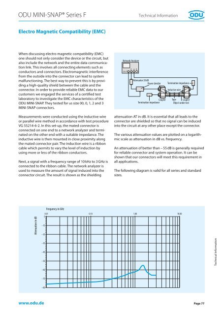
<strong>ODU</strong> <strong>MINI</strong>-<strong>SNAP®</strong> Series FTechnical InformationElectro Magnetic Compatibility (EMC)When discussing electro magnetic compatibility (EMC)one should not only consider the device or the circuit, butalso include the network and the entire data communicationlink. This involves all connecting elements such asconductors and connectors. Electromagnetic interferencefrom the outside into the connector can lead to systemmalfunctioning. The best way to prevent this is by providinga high-quality shield between the cable and theconnector. In order to provide reliable EMC data to ourcustomers we engaged the services of a certified testlaboratory to investigate the EMC characteristics of the<strong>ODU</strong> <strong>MINI</strong>-SNAP. They tested for us size 00, 0, 1, 2 and 3<strong>MINI</strong>-SNAP connectors.Network AnalyzerAttenuator 20 dBPower deviderCouplerTermination impedanceTermination impedanceInductive wireTape CouplerObject under testMeasurements were conducted using the inductive wireor parallel wire method in accordance with test procedureVG 55214-6-2. In this set-up, the mated connector isconnected on one end to a network analyzer and terminatedon the other end with a suitable impedance. Theinductive wire is then mounted in close proximity alongthe mated connector pair. The induction wire is a ribboncable which permits to vary the level of induction byusing more or less of the ribbon conductors.Next, a signal with a frequency range of 10 kHz to 3 GHz isconnected to the ribbon cable. The network analyzer isused to measure the amount of signal induced into theconnector circuit. The result is shown as the shieldingattenuation AT in dB. It is essential that all leads to theconnector are shielded so that no signal can be inducedinto the circuit at any other place except the connector.The various attenuation values are plotted on a logarithmicscale as attenuation in dB vs. frequency.An attenuation of better than – 55 dB is generally requiredfor reliable connector and system operation. It can beshown that our connectors will meet this requirement inall applications.The following diagram is valid for all series and standardsizes.Attenuation in dB−10−20Frequency in GHz0.01 0.10 1.00 10.000−30−40−50Technical Information−60−70−80www.odu.dePage 77