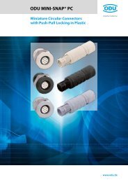
ODU MINI-SNAP®
ODU MINI-SNAP
ODU MINI-SNAP
- No tags were found...
You also want an ePaper? Increase the reach of your titles
YUMPU automatically turns print PDFs into web optimized ePapers that Google loves.
<strong>ODU</strong> <strong>MINI</strong>-<strong>SNAP®</strong> Series FTechnical InformationTechnical Information / Definitions / TermsTechnical InformationAir gapShortest distance between two conductive elementsthrough the air.AutoclavabilitySee page 78.AWGSee page 74.Creepage distanceThe distance measured across the surface of a dielectricbetween two contacts or a contact and a metal part. Thelonger the distance, the lesser the risk of damage ortracking. Minimum creepage distances are specifiedaccording to the operating voltage and the applicableisolation group.Crimping areaThe part of a crimp barrel at which the crimp connectionis achieved by pressure deformation or by reshaping thebarrel around the conductor.Crimp barrelA hollow part of a contact which accepts one or moreconductors and which may be crimped through theapplication of a crimping tool.Crimp connectionThe permanent attachment of a contact to a conductorby pressure deformation or by reshaping the crimp barrelaround the conductor so that a good electrical and mechanicalconnection is established (see page 73).ConnectorA component which terminates conductors for the purposeof providing connection and disconnection to asuitable mating component. Depending on the fasteningto a cabinet, panel, rack etc. or a cable, they are classification.DeliveryDelivery of the connectors usually as components (thatmeans not assembled).Exception: Solder contacts are factory-installed in theinsulation body.Fixed connectorA connector for attachment to a rigid surface (panel).Free connectorA connector for attachment to the free end of a wire orcable. Also called free hanging connector or in-linereceptacle.Insertion or withdrawal forceThe force required to fully mate or unmate a set of connectorswithout the effect of coupling, locking or similardevices. The insertion force is usually greater than thewithdrawal force. Also called mating and unmating force.Insulation bodyNon-conductive part of a connector, to electrically andmechanically separate live parts and to protect againstaccidental touch.Insulation groupClassification of connectors according to the operatingand working conditions (insulation groups accordingDIN VDE 0110).KeyingSystem of projections and grooves on mating connectorswhich prevent otherwise identical connectors from beingmated. This is useful when several connectors of the samestyle are used in the same application (see page 54).Lower limit temperatureThe lowest permissible temperature which a connector ora plug-in device is allowed to be operated.MaterialsThe contacts are made of Cu-alloy and gold-plated. Thestandard housings are made of Cu-alloy with a mattchrome plated surface finish. All other materials andsurfaces on special request (see page 72).Mating cyclesMechanical operation of connectors and plug-in devicesby insertion and withdrawal. One mating cycle comprisesone insertion and one withdrawal operation.Nominal single contact current loadCurrent load, which can load every single contact (seepage 75).Nominal voltageNominal voltage characterizes a component.Operating temperature of the <strong>ODU</strong> <strong>MINI</strong>-SNAPRange between upper and lower temperature limits.− 40° C to +120° C (see page 7).Print (PCB) connectionSee page 73.Page 80www.odu.de


