IntesisBox PA-AC-KNX-1i
User's manual - intesis
User's manual - intesis

You also want an ePaper? Increase the reach of your titles
YUMPU automatically turns print PDFs into web optimized ePapers that Google loves.
<strong>IntesisBox</strong> ®<strong>PA</strong>-<strong>AC</strong>-<strong>KNX</strong>-<strong>1i</strong> v1.2User's ManualIssue Date: 15/02/2012r3 eng
<strong>IntesisBox</strong> ® <strong>KNX</strong> - Panasonic A.C. (Etherea line)User's manual r3 eng© Intesis Software S.L. All Rights Reserved.Information in this document is subject to change without notice. The software described inthis document is furnished under a license agreement or nondisclosure agreement. Thesoftware may be used only in accordance with the terms of those agreements. No part ofthis publication may be reproduced, stored in a retrieval system or transmitted in any formor any means electronic or mechanical, including photocopying and recording for anypurpose other than the purchaser’s personal use without the written permission of IntesisSoftware S.L.Intesis Software S.L.Milà I Fontanals, 1 bis, 1º08700 IgualadaSpainTRADEMARKSAll trademarks and trade names used in this document are acknowledged to be the copyright of their respective holders.© Intesis Software S.L. - All rights reservedThis information is subject to change without notice<strong>IntesisBox</strong> ® is a registered trademark of Intesis Software SLURLEmailtelhttp://www.intesis.cominfo@intesis.com+34 9380471342 / 66
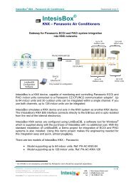
<strong>IntesisBox</strong> ® <strong>KNX</strong> - Panasonic A.C. (Etherea line)User's manual r3 engGateway for integration of Panasonic airconditioners into <strong>KNX</strong> TP-1 (EIB) control systems.Compatible with Etherea line air conditioners commercialized byPanasonic.Application’s Program Version: 1.2Order Code: <strong>PA</strong>-<strong>AC</strong>-<strong>KNX</strong>-<strong>1i</strong>© Intesis Software S.L. - All rights reservedThis information is subject to change without notice<strong>IntesisBox</strong> ® is a registered trademark of Intesis Software SLURLEmailtelhttp://www.intesis.cominfo@intesis.com+34 9380471343 / 66
<strong>IntesisBox</strong> ® <strong>KNX</strong> - Panasonic A.C. (Etherea line)User's manual r3 engINDEX1. Presentation .................................................................................................... 62. Connection ...................................................................................................... 73. Configuration and setup .................................................................................... 84. ETS Parameters ............................................................................................... 94.1 General dialog ............................................................................................ 104.1.1 Send READs for Control_ objects on bus recovery ..................................... 104.1.2 Scene to load on bus recovery / startup ................................................... 104.1.3 Disallow control from remote controller .................................................... 104.1.4 Enable func “Control_ Lock Control Obj” ................................................... 114.1.5 Enable func “Operating Hours Counter” .................................................... 114.1.6 Enable object “Error Code [2byte]”.......................................................... 124.1.7 Enable object “Error Text Code [14byte]” ................................................. 124.2 Mode Configuration dialog ............................................................................ 134.2.1 Indoor unit has HEAT mode .................................................................... 134.2.2 Indoor unit has FAN mode ...................................................................... 134.2.3 When mode is AUTO Status_ objs report actual operating status ................. 144.2.4 Enable use of Heat / Cool bit-type obj ...................................................... 144.2.5 Enable PID-Compat. Scaling Mode Objects ............................................... 144.2.6 Enable use of + / - object for Mode ......................................................... 154.2.7 Enable use of bit-type Mode objects (for control) ...................................... 164.2.8 Enable use of bit-type Mode objects (for status)........................................ 164.2.9 Enable use of Text object for Mode .......................................................... 164.3 Special Modes Configuration dialog ................................................................ 174.3.1 Enable use of “POWERFUL” mode (<strong>AC</strong> feature) .......................................... 184.3.2 Enable use of “QUIET” mode (<strong>AC</strong> feature) ................................................ 184.3.3 Enable use of POWER mode .................................................................... 184.3.4 Enable use of ECONOMY mode ................................................................ 194.3.5 Enable use of ADDITIONAL HEATING mode .............................................. 204.3.6 Enable use of ADDITIONAL COOLING mode .............................................. 214.4 Fan Speed Configuration dialog ..................................................................... 224.4.1 Enable “Fan Speed Manual/Auto” objects for Control and Status ................. 224.4.2 DPT object type for fanspeed .................................................................. 224.4.3 Enable use of +/- object for Fan Speed .................................................... 244.4.4 Enable use of bit-type Fan Speed objects (for Control) ............................... 254.4.5 Enable use of bit-type Fan Speed objects (for Status) ................................ 254.4.6 Enable use of Text object for Fan Speed ................................................... 254.5 Vane Up-Down Configuration dialog ............................................................... 264.5.1 Indoor unit has Up-Down Vanes .............................................................. 264.5.2 Enable “Vanes Up-Down Manual/Auto” objects for Control and Status .......... 274.5.3 DPT object type for Vane Up-Down .......................................................... 274.5.4 Enable use of +/- obj for Vane Up-Down .................................................. 284.5.5 Enable use of bit-type Vane U-D objects (for Control) ................................ 294.5.6 Enable use of bit-type Vane U-D objects (for Status) ................................. 294.5.7 Enable use of Text object for Vane U-D .................................................... 304.6 Vane Left-Right Configuration dialog .............................................................. 304.6.1 Indoor unit has Left-Right Vanes ............................................................. 314.6.2 Enable “Vanes Left-Right Manual/Auto” objects for Control and Status ......... 314.6.3 DPT object type for Vane Left-Right ......................................................... 314.6.4 Enable use of +/- obj for Vane Left-Right ................................................. 334.6.5 Enable use of bit-type Vane Left-Right objects (for Control) ........................ 344.6.6 Enable use of bit-type Vane Left-Right objects (for Status) ......................... 344.6.7 Enable use of Text object for Vane Left-Right ........................................... 344.7 Temperature Configuration dialog.................................................................. 35© Intesis Software S.L. - All rights reservedThis information is subject to change without notice<strong>IntesisBox</strong> ® is a registered trademark of Intesis Software SLURLEmailtelhttp://www.intesis.cominfo@intesis.com+34 9380471344 / 66
<strong>IntesisBox</strong> ® <strong>KNX</strong> - Panasonic A.C. (Etherea line)User's manual r3 eng4.7.1 Periodic sending of “Status_ <strong>AC</strong> Setp” ...................................................... 354.7.2 Enable use of +/- object for Setpoint Temperature .................................... 364.7.3 Enable limits on Control_ Setpoint obj ..................................................... 364.7.4 Ambient temp. ref. is provided from <strong>KNX</strong> ................................................. 374.8 Scene Configuration dialog ........................................................................... 384.8.1 Enable use of scenes ............................................................................. 384.8.2 Scenes can be stored from <strong>KNX</strong> bus ........................................................ 384.8.3 Enable use of bit objects for scene execution ............................................ 394.8.4 Scene “x” preset ................................................................................... 394.9 Switch-Off Timeouts Configuration dialog ....................................................... 414.9.1 Enable use of Open Window / Switch off timeout function .......................... 414.9.2 Enable use of Occupancy function ........................................................... 434.9.3 Enable use of SLEEP timeout .................................................................. 454.10 Binary Input “x” Configuration dialog ............................................................. 464.10.1 Enable use of Input “x” .......................................................................... 464.10.2 Contact type ......................................................................................... 464.10.3 Debounce time ..................................................................................... 464.10.4 Disabling function.................................................................................. 474.10.5 Function ............................................................................................... 475. Specifications ................................................................................................. 556. <strong>AC</strong> Unit Types compatibility. ............................................................................ 567. Error Codes ................................................................................................... 57Appendix A – Communication Objects Table ................................................................ 59© Intesis Software S.L. - All rights reservedThis information is subject to change without notice<strong>IntesisBox</strong> ® is a registered trademark of Intesis Software SLURLEmailtelhttp://www.intesis.cominfo@intesis.com+34 9380471345 / 66
<strong>IntesisBox</strong> ® <strong>KNX</strong> - Panasonic A.C. (Etherea line)User's manual r3 eng1. Presentation<strong>PA</strong>-<strong>AC</strong>-<strong>KNX</strong>-<strong>1i</strong> allows a complete and natural integration of<strong>PA</strong>NASONIC air conditioners with <strong>KNX</strong> control systems.Compatible with all Etherea models commercialized by<strong>PA</strong>NASONIC.Main features:Reduced dimensions, quick installation.Multiple objects for control and status (bit, byte, characters…) with <strong>KNX</strong> standarddatapoint types.Status objects for every control available.Timeout for Open Window and Occupancy. Sleep function also available.Control of the <strong>AC</strong> unit based in the ambient temperature read by the own <strong>AC</strong> unit, or inthe ambient temperature read by any <strong>KNX</strong> thermostat.<strong>AC</strong> unit can be controlled simultaneously by the IR remote control of the <strong>AC</strong> unit and by<strong>KNX</strong>.Total Control and Monitoring of the <strong>AC</strong> unit from <strong>KNX</strong>, including monitoring of <strong>AC</strong> unit’sstate of internal variables, running hours counter (for filter maintenance control), anderror indication and error code.Up to 5 scenes can be saved and executed from <strong>KNX</strong>, fixing the desired combination ofOperation Mode, Set Temperature, Fan Speed, Vane Position and Remote ControllerLock in any moment by using a simple switching.Four potential-free binary inputs provide the possibility to integrate many types of externaldevices. Also configurable from ETS, they can be used for switching, dimming, shutter/blindcontrol, and more© Intesis Software S.L. - All rights reservedThis information is subject to change without notice<strong>IntesisBox</strong> ® is a registered trademark of Intesis Software SLURLEmailtelhttp://www.intesis.cominfo@intesis.com+34 9380471346 / 66
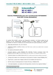
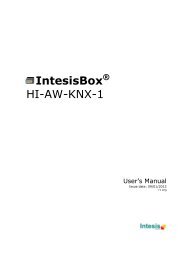
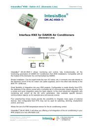
<strong>AC</strong> UnitPROG- +Phys. Addr.<strong>IntesisBox</strong> ®www.intesis.com<strong>IntesisBox</strong> ® <strong>KNX</strong> - Panasonic A.C. (Etherea line)User's manual r3 eng2. ConnectionThe interface comes with a cable (1,9 meters long) for direct connection to the internalcontrol board of the <strong>AC</strong> indoor unit.oConnection of the interface to the <strong>AC</strong> indoor unit:Disconnect mains power from the <strong>AC</strong> unit. Open the front cover of the indoor unit in orderto have access to the internal control board. In the control board locate the socketconnector marked as:CN-CNTin Etherea line units.Using the cable that comes with the interface, insert one of its connectors, the one installedin the shortest uncovered part, into the socket of the <strong>PA</strong>-<strong>AC</strong>-<strong>KNX</strong>-<strong>1i</strong> marked as <strong>AC</strong> Unit,and the other connector, the one in the largest uncovered part, into the socket CN-CNT ofthe <strong>AC</strong> unit's control board. Fix the <strong>PA</strong>-<strong>AC</strong>-<strong>KNX</strong>-<strong>1i</strong> inside or outside the <strong>AC</strong> indoor unitdepending on your needs, remember that <strong>PA</strong>-<strong>AC</strong>-<strong>KNX</strong>-<strong>1i</strong> must be also connected to the <strong>KNX</strong>bus. Close the <strong>AC</strong> indoor unit's front cover again.Important: Do not modify the length of the cable supplied with the interface, it mayaffect to the correct operation of the interfaceoConnection of the interface to the <strong>KNX</strong> bus:Disconnect power of the <strong>KNX</strong> bus. Connect the interface to the <strong>KNX</strong> TP-1 (EIB) bus usingthe <strong>KNX</strong> standard connector (red/grey) of the interface, respect polarity. Reconnect powerof the <strong>KNX</strong> bus.oConnections diagram:<strong>AC</strong> indoor unitPotential-freebinary inputs.Internalcontrol boardCN-CNTConnection cablesupplied with theinterface.<strong>KNX</strong>-+<strong>PA</strong>-<strong>AC</strong>-<strong>KNX</strong>-<strong>1i</strong>IN1IN2IN3IN4COM<strong>KNX</strong> TP-1(EIB) busFigure 2.2 Connection diagram© Intesis Software S.L. - All rights reservedThis information is subject to change without notice<strong>IntesisBox</strong> ® is a registered trademark of Intesis Software SLURLEmailtelhttp://www.intesis.cominfo@intesis.com+34 9380471347 / 66
<strong>IntesisBox</strong> ® <strong>KNX</strong> - Panasonic A.C. (Etherea line)User's manual r3 eng3. Configuration and setupThis is a fully compatible <strong>KNX</strong> device which must be configured and setup using standard<strong>KNX</strong> tool ETS.ETS database for this device can be downloaded from:http://www.intesis.com/down/eib/<strong>PA</strong>-<strong>AC</strong>-<strong>KNX</strong>-<strong>1i</strong>.zipPlease consult the README.txt file, located inside the downloaded zip file, to findinstructions on how to install the database.Important: Do not forget to select the correct settings of <strong>AC</strong> indoor unit beingconnected to the <strong>PA</strong>-<strong>AC</strong>-<strong>KNX</strong>-<strong>1i</strong> (Fan speed and Vanes), this is in "Parameters" of thedevice in ETS.© Intesis Software S.L. - All rights reservedThis information is subject to change without notice<strong>IntesisBox</strong> ® is a registered trademark of Intesis Software SLURLEmailtelhttp://www.intesis.cominfo@intesis.com+34 9380471348 / 66
<strong>IntesisBox</strong> ® <strong>KNX</strong> - Panasonic A.C. (Etherea line)User's manual r3 eng4. ETS ParametersWhen imported to the ETS software for the first time, the gateway shows the followingdefault parameter configuration:Figure 4.1 Default parameter configurationWith this configuration it’s possible to send On/Off (Control_ On/Off), change the <strong>AC</strong> Mode(Control_ Mode), the Fan Speed (Control_ Fan Speed) and also the Setpoint Temperature(Control_ Setpoint Temperature). The Status_ objects, for the mentioned Control_ objects,are also available to use if needed. Also objects Status_ <strong>AC</strong> Setpoint Temp and Status_Error/Alarm are shown.Figure 4.2 Default communication objects© Intesis Software S.L. - All rights reservedThis information is subject to change without notice<strong>IntesisBox</strong> ® is a registered trademark of Intesis Software SLURLEmailtelhttp://www.intesis.cominfo@intesis.com+34 9380471349 / 66
<strong>IntesisBox</strong> ® <strong>KNX</strong> - Panasonic A.C. (Etherea line)User's manual r3 eng4.1 General dialogInside this parameter’s dialog it is possible to activate or change the parameters shown inthe Figure 4.1.The first field shows the URL where to download the database and the user manual for theproduct.4.1.1 Send READs for Control_ objects on bus recoveryWhen this parameter is enabled, <strong>PA</strong>-<strong>AC</strong>-<strong>KNX</strong>-<strong>1i</strong> will send READ telegrams for the groupaddresses associated on its Control_ objects on bus recovery or application reset/start-up.ooIf set to “no” the gateway will not perform any action.If set to “yes” all Control_ objects with both Transmit (T) and Update (U) flags enabledwill send READs and their values will be updated with the response when received.‣ Delay before sending READs (sec):Figure 4.4 Parameter detailWith this parameter, a delay can be configured between 0 and 30 seconds for theREADs sent by the Control_ objects. This is to give time enough to other <strong>KNX</strong>devices on the bus to start-up before sending the READs.4.1.2 Scene to load on bus recovery / startupThis parameter executes a selected scene on bus recovery or startup, only if the selectedscene has an enabled preset or values previously saved from <strong>KNX</strong> bus (see SceneConfiguration dialog).If the gateway is disconnected from the indoor unit the scene will not be applied, even whenconnecting to the indoor unit again.Figure 4.5 Parameter detail4.1.3 Disallow control from remote controllerThis parameter allows:1- Having the remote controller always locked, or2- Decide through a new communication object if the RC is locked or not.oIf set to “yes” all the actions performed through the remote controller will be disabled.© Intesis Software S.L. - All rights reservedThis information is subject to change without notice<strong>IntesisBox</strong> ® is a registered trademark of Intesis Software SLURLEmailtelhttp://www.intesis.cominfo@intesis.com+34 93804713410 / 66
<strong>IntesisBox</strong> ® <strong>KNX</strong> - Panasonic A.C. (Etherea line)User's manual r3 engoIf set to “no” the remote controller will work as usually. It also appears a newparameter and the communication object Control_ Lock Remote Control.Figure 4.6 Communication object and parameter detail‣ Enable comm obj “Ctrl_ Remote Lock”:If set to “no” the object will not be shown.If set to “yes” the Control_ Lock Remote Control object will appear.When a “1” value is sent to this communication object, the remote controlleris locked. To be unlocked a “0” value must be sent. The gateway remembersthe last value received even if a <strong>KNX</strong> bus reset/failure happens.Important: If an initial scene is enabled and it has as Value for Remote Lock(unchanged) or unlocked, this would unlock the remote controller because theinitial scene has priority over the Control_ Lock Remote Controlcommunication object.4.1.4 Enable func “Control_ Lock Control Obj”This parameter shows/hide the Control_ Lock Control Obj communication object which,depending on the sent value, locks or unlocks ALL the Control_ communication objectsexcept itself.ooIf set to “no” the object will not be shown.If set to “yes” the Control_ Lock Control Objects object will appear.When a “1” value is sent to this communication object, all the Control_objects will be locked. To unlock a “0” value must be sent, as the gatewayremembers the last value received even if a <strong>KNX</strong> bus reset/failure happens.4.1.5 Enable func “Operating Hours Counter”This parameter shows/hides the Status_ Operation Hour Counter communication objectwhich counts the number of operating hours for the <strong>PA</strong>-<strong>AC</strong>-<strong>KNX</strong>-<strong>1i</strong>.oIf set to “no” the object will not be shown.© Intesis Software S.L. - All rights reservedThis information is subject to change without notice<strong>IntesisBox</strong> ® is a registered trademark of Intesis Software SLURLEmailtelhttp://www.intesis.cominfo@intesis.com+34 93804713411 / 66
<strong>IntesisBox</strong> ® <strong>KNX</strong> - Panasonic A.C. (Etherea line)User's manual r3 engoIf set to “yes” the Status_ Operation Hour Counter object will appear.This object can be read and sends its status every time an hour is counted.The gateway keeps that count in memory and the status is sent also after a<strong>KNX</strong> bus reset/failure. Although this object is marked as a Status_ object italso can be written to update the counter when needed. To reset the countershould be written a “0” value.Important: This object comes by default without the write (W) flagactivated. If is necessary to write on it, this flag must be activated.Important: This object will also return its status, every time a value iswritten, only if it’s different from the existing one.Important: If the stored value is 0 hours, the gateway will not send thestatus to <strong>KNX</strong>.4.1.6 Enable object “Error Code [2byte]”This parameter shows/hides the Status_ Error Code communication object which shows theindoor unit errors, if occurred, in numeric format.ooIf set to “no” the object will not be shown.If set to “yes” the Status_ Error Code [2byte] object will appear.This object can be read and also sends the indoor unit error, if occurred, innumeric format. If a “0” value is shown that means no error.4.1.7 Enable object “Error Text Code [14byte]”This parameter shows/hides the Status_ Error Text Code communication object whichshows the indoor unit errors, if occurred, in text format.ooIf set to “no” the object will not be shown.If set to “yes” the Status_ Error Text Code object will appear.This object can be read and also sends the indoor unit error, if occurred, intext format. The errors shown have the same format as at the remotecontroller and at the error list from the indoor unit manufacturer. If theobject’s value is empty that means no error.© Intesis Software S.L. - All rights reservedThis information is subject to change without notice<strong>IntesisBox</strong> ® is a registered trademark of Intesis Software SLURLEmailtelhttp://www.intesis.cominfo@intesis.com+34 93804713412 / 66
<strong>IntesisBox</strong> ® <strong>KNX</strong> - Panasonic A.C. (Etherea line)User's manual r3 eng4.2 Mode Configuration dialogFigure 4.7 Default Mode Configuration dialogAll the parameters in this section are related with the different mode properties andcommunication objects.The byte-type communication object for Mode works with the DTP_20.105. Auto mode willbe enabled with a “0” value, Heat mode with a “1” value, Cool mode with a “3” value, Fanmode with a “9” value and Dry mode with a “14” value.4.2.1 Indoor unit has HEAT modeThis parameter has to be used to indicate if the indoor unit has the heating mode operationavailable.ooIf set to “no”, the indoor unit doesn’t have the heating mode operation available.If set to “yes”, the infoor unit has the heating mode operation available.Important: Read the documentation of your indoor unit to check if it has HEAT modeavailable.4.2.2 Indoor unit has FAN modeThis parameter has to be used to indicate if the indoor unit has the fan mode available.ooIf set to “no”, the indoor unit doesn’t have the fan mode available.If set to “yes”, the infoor unit has the fan mode available.Important: Read the documentation of your indoor unit to check if it has FAN modeavailable.© Intesis Software S.L. - All rights reservedThis information is subject to change without notice<strong>IntesisBox</strong> ® is a registered trademark of Intesis Software SLURLEmailtelhttp://www.intesis.cominfo@intesis.com+34 93804713413 / 66
<strong>IntesisBox</strong> ® <strong>KNX</strong> - Panasonic A.C. (Etherea line)User's manual r3 eng4.2.3 When mode is AUTO Status_ objs report actual operating statusThis parameter shows the real status of the indoor unit when Auto mode is enabled.ooIf set to “no”, when the indoor unit is set to Auto mode, all the Status_ objectsconcerning mode will only show Auto enabled.If set to “yes”, when the indoor unit is set to Auto mode, all the Status_ objectsconcerning mode will show the real mode which the machine is working (Cool, Heat,Dry, Fan). In case of the bitfield objects, also the Status_ Mode Auto will be shownenabled with a “1” value.4.2.4 Enable use of Heat / Cool bit-type objThis parameter shows/hides the Control_ and Status_ Mode Cool/Heat communicationobjects.ooIf set to “no” the objects will not be shown.If set to “yes” the Control_ and Status_ Mode Cool/Heat objects will appear.When a “1” value is sent to the Control_ communication object, Heat modewill be enabled in the indoor unit, and the Status_ object will return thisvalue.When a “0” value is sent to the Control_ communication object, Cool modewill be enabled in the indoor unit, and the Status_ object will return thisvalue.4.2.5 Enable PID-Compat. Scaling Mode ObjectsThis parameter shows/hides the Control_ Mode Cool & On and Control_ Mode Heat & Oncommunication objects.ooIf set to “no” the objects will not be shown.If set to “yes” the Control_ Mode Cool & On and Control_ Mode Heat & On objects willappear.These objects provide compatibility with those <strong>KNX</strong> thermostats that controlthe demand of heating or cooling by using scaling (percentage) objects. Inthese thermostats, the percentage demand is meant to be applied on a fluidvalve of the heating / cooling system.© Intesis Software S.L. - All rights reservedThis information is subject to change without notice<strong>IntesisBox</strong> ® is a registered trademark of Intesis Software SLURLEmailtelhttp://www.intesis.cominfo@intesis.com+34 93804713414 / 66
<strong>IntesisBox</strong> ® <strong>KNX</strong> - Panasonic A.C. (Etherea line)User's manual r3 eng<strong>PA</strong>-<strong>AC</strong>-<strong>KNX</strong>-<strong>1i</strong> device does not provide individual control on the internal partsof the indoor unit (as can be its compressor, refrigerant valves, etc). Rather,it provides the same level of control as a (user) remote controller.Objects “Control_ Mode Cool & On” and “Control_ Mode Heat & On” intend tobring compatibility between thermostats oriented to the control of customheating / cooling systems and ready-made <strong>AC</strong> indoor units, by applying thefollowing logic:Whenever a non-zero value (>0%) is received at “Control_ Mode Cool& On”, indoor unit will switch On in COOL mode.Whenever a non-zero value (>0%) is received at “Control_ Mode Heat& On”, indoor unit will switch On in HEAT mode.Lastest updated object will define the operating mode Indoor unit will switch off only when both objects become zero (0%) –or when an OFF is requested at object “0. On/Off [DPT_1.001 - 1bit]”Important: These objects function is only to send On/Off and Cool/Heat to the indoorunit. The PID (Inverter system) is calculated by the indoor unit itself. Please considerintroducing an appropriate PID configuration to the external <strong>KNX</strong> thermostat to notinterfere the indoor unit PID.4.2.6 Enable use of + / - object for ModeThis parameter shows/hides the Control_ Mode +/- communication object which lets changethe indoor unit mode by using two different datapoint types.ooIf set to “no” the object will not be shown.If set to “yes” the Control_ Mode +/- object and a new parameter will appear.Figure 4.8 Parameter detail‣ DPT type for +/- Mode ObjectThis parameter lets choose between the datapoints 0-Up / 1-Down [DPT_1.008]and 0-Decrease / 1-Increase [DPT_1.007] for the Control_ Mode +/- object.© Intesis Software S.L. - All rights reservedThis information is subject to change without notice<strong>IntesisBox</strong> ® is a registered trademark of Intesis Software SLURLEmailtelhttp://www.intesis.cominfo@intesis.com+34 93804713415 / 66
<strong>IntesisBox</strong> ® <strong>KNX</strong> - Panasonic A.C. (Etherea line)User's manual r3 engThe sequence followed when using this object is shown below:AUTO HEAT COOL FANDRY• Up / Increase• Down / Decrease4.2.7 Enable use of bit-type Mode objects (for control)This parameter shows/hides the bit-type Control_ Mode objects.ooIf set to “no” the objects will not be shown.If set to “yes” the Control_ Mode objects for Auto, Heat, Cool, Fan and Dry will appear.To activate a mode by using these objects a “1” value has to be sent.4.2.8 Enable use of bit-type Mode objects (for status)This parameter shows/hides the bit-type Status_ Mode objects.ooIf set to “no” the objects will not be shown.If set to “yes” the Status_ Mode objects for Auto, Heat, Cool, Fan and Dry will appear.When enabled, a mode will return a “1” through its bit-type object.4.2.9 Enable use of Text object for ModeThis parameter shows/hides the Status_ Mode Text communication object.oIf set to “no” the object will not be shown.© Intesis Software S.L. - All rights reservedThis information is subject to change without notice<strong>IntesisBox</strong> ® is a registered trademark of Intesis Software SLURLEmailtelhttp://www.intesis.cominfo@intesis.com+34 93804713416 / 66
<strong>IntesisBox</strong> ® <strong>KNX</strong> - Panasonic A.C. (Etherea line)User's manual r3 engoIf set to “yes” the Status_ Mode Text object will appear. Also, in the parameters, will beshown five text fields, one for each mode, that will let modify the text string displayedby the Status_ Mode Text when changing mode.Figure 4.9 Parameter detail4.3 Special Modes Configuration dialogFigure 4.10 Default Special Modes Configuration dialogThe Special Modes can be parameterized through the ETS parameters dialog, and they canbe used to give extra functionality.Important: When executing any of the Special Modes (excluding POWERFUL and QUIETmodes), the real state of the indoor unit will NOT be shown in <strong>KNX</strong>.Important: When the predefined time for the Special Mode is finished or a “0” value issent to stop it, the previous state will be recovered (excluding in POWERFUL and QUIETmodes).Important: If a value concerning On/Off, Mode, Fan Speed or Setpoint Temperature isreceived from <strong>KNX</strong> while any Special Mode (excluding POWERFUL and QUIET modes) isrunning (“1”), the Special Mode will stop and the previous state will be recovered. Thevalue received will be also applied then.Important: If a value concerning On/Off, Mode, Fan Speed or Setpoint Temperature ismodified through the remote controller, the Special Mode (excluding POWERFUL andQUIET modes) will stop WITHOUT recovering the previous state. Then the real indoorunit state will be shown in <strong>KNX</strong> including the new value received through the remotecontroller.© Intesis Software S.L. - All rights reservedThis information is subject to change without notice<strong>IntesisBox</strong> ® is a registered trademark of Intesis Software SLURLEmailtelhttp://www.intesis.cominfo@intesis.com+34 93804713417 / 66
<strong>IntesisBox</strong> ® <strong>KNX</strong> - Panasonic A.C. (Etherea line)User's manual r3 eng4.3.1 Enable use of “POWERFUL” mode (<strong>AC</strong> feature)This parameter shows/hides the Control_ Powerful and Status_ Powerful communicationobjects.Important: The Powerful Mode is an internal <strong>AC</strong> feature. Please check the indoor unituser’s manual to have more information about it.ooIf set to “no” the object will not be shown.If set to “yes” the Control_ Po1werful and Status_ Powerful objects will appear.When a “1” value is sent to the Control_ communication object, PowerfulMode will be enabled, and the Status_ object will return this value.When a “0” value is sent to the Control_ communication object, PowerfulMode will be disabled, and the Status_ object will return this value.4.3.2 Enable use of “QUIET” mode (<strong>AC</strong> feature)This parameter shows/hides the Control_ Quiet and Status_ Quiet communication objects.Important: The Quiet Mode is an internal <strong>AC</strong> feature. Please check the indoor unituser’s manual to have more information about it.ooIf set to “no” the object will not be shown.If set to “yes” the Control_ Quiet and Status_ Quiet objects will appear.When a “1” value is sent to the Control_ communication object, Quiet Modewill be enabled, and the Status_ object will return this value.When a “0” value is sent to the Control_ communication object, Quiet Modewill be disabled, and the Status_ object will return this value.4.3.3 Enable use of POWER modeThis parameter shows/hides the Control_ Power Mode and Status_ Power Modecommunication objects. The Power Mode lets change the Setpoint Temperature and the FanSpeed within a given period of time.© Intesis Software S.L. - All rights reservedThis information is subject to change without notice<strong>IntesisBox</strong> ® is a registered trademark of Intesis Software SLURLEmailtelhttp://www.intesis.cominfo@intesis.com+34 93804713418 / 66
<strong>IntesisBox</strong> ® <strong>KNX</strong> - Panasonic A.C. (Etherea line)User's manual r3 engooIf set to “no” the objects will not be shown.If set to “yes” the Control_ Power Mode and Status_ Power Mode objects and newparameters will appear.Figure 4.11 Parameter detailWhen a “1” value is sent to the Control_ communication object Power Modewill be enabled, and the Status_ object will return this value.When a “0” value is sent to the Control_ communication object, Power Modewill be disabled, and the Status_ object will return this value.Important: This mode will ONLY work if the indoor unit is both turned on andin a Heat, Cool, Auto-Heat or Auto-Cool Mode.‣ Action time for this mode (minutes):Duration of Power Mode, in minutes, once started.‣ Setpoint delta increase (HEAT) or decrease (COOL) – in Celsius:Number of degrees Celsius that will increase in Heat Mode, or decrease in Cool Mode,while in Power Mode.‣ Fan Speed for this mode:Fan Speed that will be set in the unit while in Power Mode.4.3.4 Enable use of ECONOMY modeThis parameter shows/hides the Control_ Econo Mode and Status_ Econo Modecommunication objects. The Econo Mode lets change the Setpoint Temperature and the FanSpeed within a given period of time.ooIf set to “no” the objects will not be shown.If set to “yes” the Control_ Econo Mode and Status_ Econo Mode objects and newparameters will appear.© Intesis Software S.L. - All rights reservedThis information is subject to change without notice<strong>IntesisBox</strong> ® is a registered trademark of Intesis Software SLURLEmailtelhttp://www.intesis.cominfo@intesis.com+34 93804713419 / 66
<strong>IntesisBox</strong> ® <strong>KNX</strong> - Panasonic A.C. (Etherea line)User's manual r3 engWhen a “1” value is sent to the Control_ communication object, EconoModewill be enabled, and the Status_ object will return this value.When a “0” value is sent to the Control_ communication object, EconoModewill be disabled, and the Status_ object will return this value.Important: This mode will ONLY work if the indoor unit is both turned on andin a Heat, Cool, Auto-Heat or Auto-Cool Mode.‣ Action time for this mode (minutes):Duration of EconoMode, in minutes, once started.‣ Setpoint delta increase (HEAT) or decrease (COOL) – in Celsius:Number of degrees Celsius that will increase in Heat Mode, or decrease in Cool Mode,while in EconoMode.‣ Fan Speed for this mode:Fan Speed that will be set in the unit while in EconoMode.4.3.5 Enable use of ADDITIONAL HEATING modeThis parameter shows/hides the Control_ Start Additional Heat Mode and Status_ AdditionalHeat Mode communication objects. The Additional Heating Mode lets change the SetpointTemperature and the Fan Speed within a given period of time.ooIf set to “no” the objects will not be shown.If set to “yes” the Control_ Start Additional Heat Mode and Status_ Additional HeatMode objects and new parameters will appear.When a “1” value is sent to the Control_ communication object, AdditionalHeating Mode will be enabled, and the Status_ object will return this value.When a “0” value is sent to the Control_ communication object, AdditionalHeating Mode will be disabled, and the Status_ object will return this value.Important: This mode will ALWAYS turn on the indoor unit in Heat mode.‣ Action time for this mode (minutes):Duration of Additional Heating Mode, in minutes, once started.© Intesis Software S.L. - All rights reservedThis information is subject to change without notice<strong>IntesisBox</strong> ® is a registered trademark of Intesis Software SLURLEmailtelhttp://www.intesis.cominfo@intesis.com+34 93804713420 / 66
<strong>IntesisBox</strong> ® <strong>KNX</strong> - Panasonic A.C. (Etherea line)User's manual r3 eng‣ Setpoint temp for this mode (ºC):Setpoint temperature that will be applied while in Additional Heating Mode.‣ Fan Speed for this mode:Fan Speed that will be set in the unit while in Additional Heating Mode.4.3.6 Enable use of ADDITIONAL COOLING modeThis parameter shows/hides the Control_ Start Additional Cool Mode and Status_ AdditionalCool Mode communication objects. The Additional Heating Mode lets change the SetpointTemperature and the Fan Speed within a given period of time.ooIf set to “no” the objects will not be shown.If set to “yes” the Control_ Start Additional Cool Mode and Status_ Additional CoolMode objects and new parameters will appear.When a “1” value is sent to the Control_ communication object, AdditionalCooling Mode will be enabled, and the Status_ object will return this value.When a “0” value is sent to the Control_ communication object, AdditionalCooling Mode will be disabled, and the Status_ object will return this value.Important: This mode will ALWAYS turn on the indoor unit in Cool mode.‣ Action time for this mode (minutes):Duration of Additional Cooling Mode, in minutes, once started.‣ Setpoint temp for this mode (ºC):Setpoint temperature that will be applied while in Additional Cooling Mode.‣ Fan Speed for this mode:Fan Speed that will be set in the unit while in Additional Cooling Mode.© Intesis Software S.L. - All rights reservedThis information is subject to change without notice<strong>IntesisBox</strong> ® is a registered trademark of Intesis Software SLURLEmailtelhttp://www.intesis.cominfo@intesis.com+34 93804713421 / 66
<strong>IntesisBox</strong> ® <strong>KNX</strong> - Panasonic A.C. (Etherea line)User's manual r3 eng4.4 Fan Speed Configuration dialogFigure 4.12 Default Fan Speed Configuration dialogAll the parameters in this section are related with the Fan Speed properties andcommunication objects.4.4.1 Enable “Fan Speed Manual/Auto” objects for Control and StatusThis parameter shows/hides the Control_ Fan Speed Manual/Auto and Status_ Fan SpeedManual/Auto communication objects.ooIf set to “no” the objects will not be shown.If set to “yes” the Control_ Fan Speed Manual/Auto and Status_ Fan SpeedManual/Auto objects will appear.When a “1” value is sent to the Control_ communication object, Fan Speedwill be in Auto mode, and the Status_ object will return this value.When a “0” value is sent to the Control_ communication object, Fan Speedwill be in Manual mode and the first fan speed will be enabled. The Status_object will return this value.Important: When in Auto Mode the indoor unit will choose the mostappropriate fan speed, but this will be shown neither in <strong>KNX</strong> nor in the remotecontroller.4.4.2 DPT object type for fanspeedWith this parameter is possible to change de DPT for the Control_ Fan Speed and Status_Fan Speed byte-type communication objects. Datapoints Scaling (DPT_5.001) andEnumerated (DPT_5.010) can be selected.© Intesis Software S.L. - All rights reservedThis information is subject to change without notice<strong>IntesisBox</strong> ® is a registered trademark of Intesis Software SLURLEmailtelhttp://www.intesis.cominfo@intesis.com+34 93804713422 / 66
<strong>IntesisBox</strong> ® <strong>KNX</strong> - Panasonic A.C. (Etherea line)User's manual r3 engoWhen “Enumerated [DPT 5.010]” is selected, Control_ Fan Speed and Status_ FanSpeed communication objects for this DPT will appear.The first fan speed will be selected if a “1” is sent to the Control_ object. The secondone will be selected sending a “2”; the third one will be selected sending a “3”; thefourth one will be selected sending a “4”; and the last one will be selected sending a“5”.The Status_ object will always return the value for the fan speed selected.Important: If a “0” value is sent to the Control_ object, the minimum fan speedwill be selected. If a value bigger than “5” is sent to the Control_ object, then themaximum fan speed will be selected.oWhen “Scaling [DPT 5.001]” is selected, Control_ Fan Speed and Status_ Fan Speedcommunication objects for this DPT will appear.When a value between 0% and 29% is sent to the Control_ object the first fan speedwill be selected.When a value between 30% and 49% is sent to the Control_ object, the second speedwill be selected.When a value between 50% and 69% is sent to the Control_ object, the third speedwill be selected.When a value between 70% and 89% is sent to the Control_ object, the fourth speedwill be selected.When a value between 90% and 100% is sent to the Control_ object, the fifth speedwill be selected.The Status_ object will return a 20% when the first speed is selected, a 40% for thesecond one, a 60% for the third one, a 80% for the fourth one, and a 100% for thelast one.Control_ Control_ Control_objectFanSpeedSpeed11 Fan Speed 2 Fan Speed 3Control_Control_Fan Speed 4 Fan Speed 50% 20% 30% 40% 50% 60% 70% 80% 90%100%Status_Status_Status_Status_Status_© Intesis Software S.L. - All rights reservedThis information is subject to change without notice<strong>IntesisBox</strong> ® is a registered trademark of Intesis Software SLURLEmailtelhttp://www.intesis.cominfo@intesis.com+34 93804713423 / 66
<strong>IntesisBox</strong> ® <strong>KNX</strong> - Panasonic A.C. (Etherea line)User's manual r3 eng4.4.3 Enable use of +/- object for Fan SpeedThis parameter shows/hides the Control_ Fan Speed +/- communication object which letsincrease/decrease the indoor unit fan speed by using two different datapoint types.ooIf set to “no” the object will not be shown.If set to “yes” the Control_ Fan Speed +/- object and a new parameter will appear.Figure 4.13 Parameter detail‣ DPT type for +/- Fan Speed ObjectThis parameter lets choose between the datapoints 0-Up / 1-Down [DPT_1.008]and 0-Decrease / 1-Increase [DPT_1.007] for the Control_ Fan Speed +/-object.‣ Does +/- sequence include fan speed AUTO?This parameter lets choose if AUTO function is included (“yes”) or not (“no”) in thesequence when using Control_ Fan Speed +/- object as shown in the discontinuoussegment at the picture below.‣ Roll-over Speed at upper/lower limitThis parameter lets choose if roll-over will be enabled (“yes”) or disabled (“no”) forthe Control_ Fan Speed +/- object.Only if Roll-over is enabledAUTO FS 1 FS 2 FS 3Only if Roll-over is enabledFS 4FS 5• Up / Increase• Down / Decrease© Intesis Software S.L. - All rights reservedThis information is subject to change without notice<strong>IntesisBox</strong> ® is a registered trademark of Intesis Software SLURLEmailtelhttp://www.intesis.cominfo@intesis.com+34 93804713424 / 66
<strong>IntesisBox</strong> ® <strong>KNX</strong> - Panasonic A.C. (Etherea line)User's manual r3 eng4.4.4 Enable use of bit-type Fan Speed objects (for Control)This parameter shows/hides the bit-type Control_ Fan Speed objects.oIf set to “no” the objects will not be shown.o If set to “yes” the Control_ Fan Speed objects for Speed 1, Speed 2, Speed 3, Speed 4and Speed 5 will appear. To activate a Fan Speed by using these objects a “1” value hasto be sent.4.4.5 Enable use of bit-type Fan Speed objects (for Status)This parameter shows/hides the bit-type Status_ Fan Speed objects.oIf set to “no” the objects will not be shown.o If set to “yes” the Status_ Fan Speed objects for Speed 1, Speed 2, Speed 3, Speed 4and Speed 5 will appear. When a Fan Speed is enabled, a “1” value is returned throughits bit-type object.4.4.6 Enable use of Text object for Fan SpeedThis parameter shows/hides the Status_ Fan Speed Text communication object.ooIf set to “no” the object will not be shown.If set to “yes” the Status_ Fan Speed Text object will appear. Also, in the parameters,will be shown five text fields, one for each Fan Speed, that will let modify the text stringdisplayed by the Status_ Fan Speed Text when changing a fan speed.© Intesis Software S.L. - All rights reservedThis information is subject to change without notice<strong>IntesisBox</strong> ® is a registered trademark of Intesis Software SLURLEmailtelhttp://www.intesis.cominfo@intesis.com+34 93804713425 / 66
<strong>IntesisBox</strong> ® <strong>KNX</strong> - Panasonic A.C. (Etherea line)User's manual r3 engFigure 4.14 Parameter detail4.5 Vane Up-Down Configuration dialogFigure 4.15 Vane Up-Down Configuration dialogAll the parameters in this section are related with the Vane Up-Down properties andcommunication objects.4.5.1 Indoor unit has Up-Down VanesThis parameter lets choose if the unit has Up-Down Vanes available or not.Figure 4.17 Parameter detailooIf set to “no” all the parameters and communication objects for the Up-Down Vanes willnot be shown.If set to “yes” all the parameters and communication objects (if enabled in theparameters dialog) for the Up-Down Vanes will be shown.Important: Read the documentation of your indoor unit to check if Up-Down Vanes areavailable.© Intesis Software S.L. - All rights reservedThis information is subject to change without notice<strong>IntesisBox</strong> ® is a registered trademark of Intesis Software SLURLEmailtelhttp://www.intesis.cominfo@intesis.com+34 93804713426 / 66
<strong>IntesisBox</strong> ® <strong>KNX</strong> - Panasonic A.C. (Etherea line)User's manual r3 eng4.5.2 Enable “Vanes Up-Down Manual/Auto” objects for Control and StatusThis parameter shows/hides the Control_ Vanes Up-Down Man/Auto and Status_ Vanes Up-Down Man/Auto communication objects.ooIf set to “no” the objects will not be shown.If set to “yes” the Control_ Vanes Up-Down Man/Auto and Status_ Vanes Up-DownMan/Auto objects will appear.When a “1” value is sent to the Control_ communication object, Vanes Up-Down will be in Auto mode, and the Status_ object will return this value.When a “0” value is sent to the Control_ communication object, Vanes Up-Down will be in Manual mode and the first position will be enabled. TheStatus_ object will return this value.Important: When in Auto Mode the indoor unit will choose the mostappropriate vane up-down position, but this will be shown neither in <strong>KNX</strong> norin the remote controller.4.5.3 DPT object type for Vane Up-DownWith this parameter is possible to change de DPT for the Control_ Vane Up-Down andStatus_ Vane Up-Down byte-type communication objects. Datapoints Scaling (DPT_5.001)and Enumerated (DPT_5.010) can be selected.oWhen “Enumerated [DPT 5.010]” is selected, Control_ Vane Up-Down and Status_Vane Up-Down communication objects for this DPT will appear.To choose a vane position, values from “1” to “5” can be sent to the Control_ object.Each value will correspond to the position (i.e. Value “3” = Position 3).The Status_ object will always return the value for the vane position selected.Important: If a “0” value is sent to the Control_ object, the Position 1 will beselected. If a value bigger than “5” is sent to the Control_ object, then the Position5 will be selected.oWhen “Scaling [DPT 5.001]” is selected, Control_ Vane Up-Down and Status_ VaneUp-Down communication objects for this DPT will appear.© Intesis Software S.L. - All rights reservedThis information is subject to change without notice<strong>IntesisBox</strong> ® is a registered trademark of Intesis Software SLURLEmailtelhttp://www.intesis.cominfo@intesis.com+34 93804713427 / 66
<strong>IntesisBox</strong> ® <strong>KNX</strong> - Panasonic A.C. (Etherea line)User's manual r3 engWhen a value between 0% and 29% is sent to the Control_ object the first vaneposition will be selected.When a value between 30% and 49% is sent to the Control_ object, the second vaneposition will be selected.When a value between 50% and 69% is sent to the Control_ object, the third vaneposition will be selected.When a value between 70% and 89% is sent to the Control_ object, the fourth vaneposition will be selected.When a value between 90% and 100% is sent to the Control_ object, the fifth vaneposition will be selected.The Status_ object will return a 20% for the first vane position, a 40% for the secondone, a 60% for the third one, an 80% for the fourth one and a 100% for the fifth andlast one.Control_ Control_ Control_objectSpeed 1Pos. 1 Pos. 2 Pos. 3Control_0% 20% 30% 40% 50% 60% 70% 80% 90%Control_Pos. 4 Pos. 5100%Status_Status_Status_Status_Status_4.5.4 Enable use of +/- obj for Vane Up-DownThis parameter shows/hides the Control_ Vane Up-Down +/- communication object whichlets change the indoor unit vane position by using two different datapoint types.ooIf set to “no” the object will not be shown.If set to “yes” the Control_ Vane Up-Down +/- object and a new parameter will appear.Figure 4.16 Parameter detail© Intesis Software S.L. - All rights reservedThis information is subject to change without notice<strong>IntesisBox</strong> ® is a registered trademark of Intesis Software SLURLEmailtelhttp://www.intesis.cominfo@intesis.com+34 93804713428 / 66
<strong>IntesisBox</strong> ® <strong>KNX</strong> - Panasonic A.C. (Etherea line)User's manual r3 eng‣ DPT type for +/- Vane Up-Down objThis parameter lets choose between the datapoints 0-Up / 1-Down [DPT_1.008]and 0-Decrease / 1-Increase [DPT_1.007] for the Control_ Vane Up-Down +/-object.‣ Does +/- sequence include vanes Up-Down AUTO?This parameter lets choose if AUTO function is included (“yes”) or not (“no”) in thesequence when using Control_ Vane Up-Down +/- object as shown in thediscontinuous segment at the picture below.‣ Roll over Vanes at upper/lower limitThis parameter lets choose if roll-over will be enabled (“yes”) or disabled (“no”) forthe Vane Up-Down +/- object.Only if Roll-over is enabledAUTO Pos. 1 Pos. 2 Pos. 3Only if Roll-over is enabledPos. 4Pos. 5• Up / Increase• Down / Decrease4.5.5 Enable use of bit-type Vane U-D objects (for Control)This parameter shows/hides the bit-type Control_ Vane Up-Down objects.ooIf set to “no” the objects will not be shown.If set to “yes” the Control_ Vane Up-Down objects for each Position (1 to 5) will appear.To activate a Vane Position by using these objects, a “1” value has to be sent.4.5.6 Enable use of bit-type Vane U-D objects (for Status)This parameter shows/hides the bit-type Status_ Vane Up-Down objects.© Intesis Software S.L. - All rights reservedThis information is subject to change without notice<strong>IntesisBox</strong> ® is a registered trademark of Intesis Software SLURLEmailtelhttp://www.intesis.cominfo@intesis.com+34 93804713429 / 66
<strong>IntesisBox</strong> ® <strong>KNX</strong> - Panasonic A.C. (Etherea line)User's manual r3 engo When “Enumerated [DPT 5.010]” is selected, Control_ Vane L-R and Status_ Vane L-R communication objects for this DPT will appear.To choose a vane position, values from “1” to “5” can be sent to the Control_ object.Each value will correspond to the position (i.e. Value “3” = Position 3).The Status_ object will always return the value for the vane position selected.Important: If a “0” value is sent to the Control_ object, the Position 1 will beselected. If a value bigger than “5” is sent to the Control_ object, then the Position5 will be selected.oWhen “Scaling [DPT 5.001]” is selected, Control_ Vane L-R and Status_ Vane L-Rcommunication objects for this DPT will appear.When a value between 0% and 29% is sent to the Control_ object the first vaneposition will be selected.When a value between 30% and 49% is sent to the Control_ object, the second vaneposition will be selected.When a value between 50% and 69% is sent to the Control_ object, the third vaneposition will be selected.When a value between 70% and 89% is sent to the Control_ object, the fourth vaneposition will be selected.When a value between 90% and 100% is sent to the Control_ object, the fifth vaneposition will be selected.The Status_ object will return a 20% for the first vane position, a 40% for the secondone, a 60% for the third one, an 80% for the fourth one and a 100% for the fifth andlast one.Control_ Control_ Control_objectSpeed 1Pos. 1 Pos. 2 Pos. 3Control_0% 20% 30% 40% 50% 60% 70% 80% 90%Control_Pos. 4 Pos. 5100%Status_Status_Status_Status_Status_© Intesis Software S.L. - All rights reservedThis information is subject to change without notice<strong>IntesisBox</strong> ® is a registered trademark of Intesis Software SLURLEmailtelhttp://www.intesis.cominfo@intesis.com+34 93804713432 / 66
<strong>IntesisBox</strong> ® <strong>KNX</strong> - Panasonic A.C. (Etherea line)User's manual r3 eng4.6.4 Enable use of +/- obj for Vane Left-RightThis parameter shows/hides the Control_ Vane Left-Right +/- communication object whichlets change the indoor unit vane position by using two different datapoint types.ooIf set to “no” the object will not be shown.If set to “yes” the Control_ Vane Left-Right +/- object and a new parameter willappear.Figure 4.20 Parameter detail‣ DPT type for +/- Vane Left-Right objThis parameter lets choose between the datapoints 0-Up / 1-Down [DPT_1.008]and 0-Decrease / 1-Increase [DPT_1.007] for the Control_ Vane Left-Right +/-object.‣ Does +/- sequence include vanes Left-Right AUTO?This parameter lets choose if AUTO function is included (“yes”) or not (“no”) in thesequence when using Control_ Vane Left-Right +/- object as shown in thediscontinuous segment at the picture below.‣ Roll over Vanes at upper/lower limitThis parameter lets choose if roll-over will be enabled (“yes”) or disabled (“no”) forthe Vane Left-Right +/- object.Only if Roll-over is enabledAUTO Pos. 1 Pos. 2 Pos. 3Only if Roll-over is enabledPos. 4Pos. 5• Up / Increase• Down / Decrease© Intesis Software S.L. - All rights reservedThis information is subject to change without notice<strong>IntesisBox</strong> ® is a registered trademark of Intesis Software SLURLEmailtelhttp://www.intesis.cominfo@intesis.com+34 93804713433 / 66
<strong>IntesisBox</strong> ® <strong>KNX</strong> - Panasonic A.C. (Etherea line)User's manual r3 eng4.6.5 Enable use of bit-type Vane Left-Right objects (for Control)This parameter shows/hides the bit-type Control_ Vane Left-Right objects.ooIf set to “no” the objects will not be shown.If set to “yes” the Control_ Vane Left-Right objects for each Position (1 to 5) willappear. To activate a Vane Position by using these objects, a “1” value has to be sent.4.6.6 Enable use of bit-type Vane Left-Right objects (for Status)This parameter shows/hides the bit-type Status_ Vane Left-Right objects.ooIf set to “no” the objects will not be shown.If set to “yes” the Status_ Vane Left-Right objects for each Position (1 to 5) will appear.When a Vane Position is enabled, a “1” value is returned through its bit-type object.4.6.7 Enable use of Text object for Vane Left-RightThis parameter shows/hides the Status_ Vane Left-Right Text communication object.ooIf set to “no” the object will not be shown.If set to “yes” the Status_ Vane Left-Right Text object will appear. Also, in theparameters will be shown six text fields, five for the Vane Position and one for the Autofunction, that will let modify the text string displayed by the Status_ Vane Left-RightText when changing a vane position.© Intesis Software S.L. - All rights reservedThis information is subject to change without notice<strong>IntesisBox</strong> ® is a registered trademark of Intesis Software SLURLEmailtelhttp://www.intesis.cominfo@intesis.com+34 93804713434 / 66
<strong>IntesisBox</strong> ® <strong>KNX</strong> - Panasonic A.C. (Etherea line)User's manual r3 engFigure 4.21 Parameter detail4.7 Temperature Configuration dialogFigure 4.22 Default Temperature Configuration dialogAll the parameters in this section are related with the Temperature properties andcommunication objects.4.7.1 Periodic sending of “Status_ <strong>AC</strong> Setp”This parameter lets change the interval of time (in seconds, from 0 to 255) at the end ofwhich the <strong>AC</strong> setpoint temperature is sent to the <strong>KNX</strong> bus. For a “0” value, the <strong>AC</strong> setpointtemperature will ONLY be sent on change. The <strong>AC</strong> setpoint temperature is sent through thecommunication object Status_ <strong>AC</strong> Setpoint Temp.Figure 4.23 Parameter detailImportant: In case the ambient temperature is provided from <strong>KNX</strong>, the setpointtemperature returned from this object, will be the one resulting from the formula shownin the section “2.7.4 Ambient temp. ref. is provided from <strong>KNX</strong>”.© Intesis Software S.L. - All rights reservedThis information is subject to change without notice<strong>IntesisBox</strong> ® is a registered trademark of Intesis Software SLURLEmailtelhttp://www.intesis.cominfo@intesis.com+34 93804713435 / 66
<strong>IntesisBox</strong> ® <strong>KNX</strong> - Panasonic A.C. (Etherea line)User's manual r3 eng4.7.2 Enable use of +/- object for Setpoint TemperatureThis parameter shows/hides the Control_ Setpoint Temp +/- communication object whichlets change the indoor unit setpoint temperature by using two different datapoint types.ooIf set to “no” the object will not be shown.If set to “yes” the Control_ Setpoint Temp +/- object and a new parameter will appear.Figure 4.24 Parameter detail‣ DPT type for +/- Setp Temp objectThis parameter lets choose between the datapoints 0-Up / 1-Down [DPT_1.008]and 0-Decrease / 1-Increase [DPT_1.007] for the Control_ Setpoint Temp +/-object.(Lower limit) 16ºC 17ºC …31ºC 32ºC (Upper limit)4.7.3 Enable limits on Control_ Setpoint obj• Up / Increase• Down / DecreaseThis parameter enables to define temperature limits for the Control_ Setpoint Temperatureobject.Figure 4.25 Parameter detailooIf set to “no” the setpoint temperature limits for the Control_ Setpoint Temperatureobject will be the default: 16ºC for the lower limit and 32ºC for the upper limit.If set to “yes” it is possible to define temperature limits for the Control_ SetpointTemperature object.‣ Control_ Set Temp Lower limit (ºC)This parameter lets to define the lower limit for the setpoint temperature.© Intesis Software S.L. - All rights reservedThis information is subject to change without notice<strong>IntesisBox</strong> ® is a registered trademark of Intesis Software SLURLEmailtelhttp://www.intesis.cominfo@intesis.com+34 93804713436 / 66
<strong>IntesisBox</strong> ® <strong>KNX</strong> - Panasonic A.C. (Etherea line)User's manual r3 eng‣ Control_ Set Temp Upper limit (ºC)This parameter lets to define the upper limit for the setpoint temperature.Important: If a setpoint temperature above the upper defined limit (or below the lowerdefined limit) is sent through the Control_ Setpoint Temperature object, it will beALWAYS applied the limit defined.Important: When limits are enabled, any setpoint temperature sent to the <strong>AC</strong> (eventhrough scenes, special modes, etc.) will be limited.4.7.4 Ambient temp. ref. is provided from <strong>KNX</strong>This parameter shows/hides the Control_ Ambient Temperature communication objectwhich lets use an ambient temperature reference provided by a <strong>KNX</strong> device.ooIf set to “no” the object will not be shown.If set to “yes” the Control_ Ambient Temperature object will appear. Meant to beenabled when you want the temperature provided by a <strong>KNX</strong> sensor to be the referenceambient temperature for the air conditioner. Then, the following formula applies forcalculation of real Control_ Setpoint Temperature sent to the <strong>AC</strong> unit:“<strong>AC</strong> Setp. Temp.” = “<strong>KNX</strong> Setp. Temp.” - (“<strong>KNX</strong> Amb. Temp.” - “<strong>KNX</strong> Setp. Temp.”)/2• <strong>AC</strong> Setp. Temp.: <strong>AC</strong> indoor unit setpoint temperature• <strong>KNX</strong> Amb. Temp.: Ambient temperature provided from <strong>KNX</strong>• <strong>KNX</strong> Setp. Temp.: Setpoint temperature provided from <strong>KNX</strong>As an example, consider the following situation:User wants: 19ºC (“<strong>KNX</strong> Setp. Temp.”)User sensor (a <strong>KNX</strong> sensor) reads: 21ºC (“<strong>KNX</strong> Amb Temp.”)In this example, the final setpoint temperature that <strong>PA</strong>-<strong>AC</strong>-<strong>KNX</strong>-<strong>1i</strong> will send out to theindoor unit (shown in “<strong>AC</strong> Setp. Temp.”) will become 19ºC – (21ºC - 19ºC)/2 = 18ºC.This is the setpoint that will actually be requested to Panasonic unit.This formula will be applied as soon as the Control_ Setpoint Temperature and Control_Ambient Temperature objects are written at least once from the <strong>KNX</strong> installation. Afterthat, they are kept always consistent.Note that this formula will always drive the <strong>AC</strong> indoor unit demand in the right direction,regardless of the operation mode (Heat, Cool or Auto).© Intesis Software S.L. - All rights reservedThis information is subject to change without notice<strong>IntesisBox</strong> ® is a registered trademark of Intesis Software SLURLEmailtelhttp://www.intesis.cominfo@intesis.com+34 93804713437 / 66
<strong>IntesisBox</strong> ® <strong>KNX</strong> - Panasonic A.C. (Etherea line)User's manual r3 eng4.8 Scene Configuration dialogFigure 4.26 Parameter detailAll the parameters in this section are related with the Scene properties and communicationobjects. A scene contains values of: On/Off, Mode, Fan speed, Vane position, SetpointTemperature and Remote Controller Disablement.4.8.1 Enable use of scenesThis parameter shows/hides the scene configuration parameters and communicationobjects.Figure 4.27 Parameter detailooIf set to “no” the scene parameters and communication objects will not be shown.If set to “yes” the scene parameters and communication objects will be shown. Toexecute a scene through the byte-type object, a value from “0” to “4” has to be sent,correponding each one to a different scene (i.e. “0” = Scene 1;… “4” = Scene 5).4.8.2 Scenes can be stored from <strong>KNX</strong> busThis parameter shows/hides the Control_ Save/Exec Scene and all the Control_ Store Scene(if enabled) communication objects.© Intesis Software S.L. - All rights reservedThis information is subject to change without notice<strong>IntesisBox</strong> ® is a registered trademark of Intesis Software SLURLEmailtelhttp://www.intesis.cominfo@intesis.com+34 93804713438 / 66
<strong>IntesisBox</strong> ® <strong>KNX</strong> - Panasonic A.C. (Etherea line)User's manual r3 engooIf set to “no” the communication objects will not be shown.If set to “yes” the communication objects and a new parameter will appear. To store ascene through the byte-type object, a value from “128” to “132” has to be sent to theobject, correponding each one to a different scene (i.e. “128” = Scene 1;… “132” =Scene 5).Figure 4.28 Parameter detail‣ Enable use of bit objects for storing scenes (from bus)If set to “no” the objects will not be shown.If set to “yes” the Control_ Store Scene objects for storing scenes will appear. Tostore a scene by using these objects, a “1” value has to be sent to the scene’sobject we want to store (i.e. to store scene 4, a “1” has to be sent to the Control_Store Scene 4 object).4.8.3 Enable use of bit objects for scene executionThis parameter shows/hides the Control_ Execute Scene bit-type communication objects.Figure 4.29 Parameter detailooIf set to “no” the communication objects will not be shown.If set to “yes” the communication objects will appear. To execute a scene by usingthese objects, a “1” value has to be sent to the scene’s object we want to execute (i.e.to execute scene 4, a “1” has to be sent to the Control_ Execute Scene 4 object).4.8.4 Scene “x” presetThis parameter lets define a preset for a scene (the following description is valid for all thescenes).© Intesis Software S.L. - All rights reservedThis information is subject to change without notice<strong>IntesisBox</strong> ® is a registered trademark of Intesis Software SLURLEmailtelhttp://www.intesis.cominfo@intesis.com+34 93804713439 / 66
<strong>IntesisBox</strong> ® <strong>KNX</strong> - Panasonic A.C. (Etherea line)User's manual r3 engFigure 4.30 Parameter detailooIf set to “no” the preset for the scene “x” will be disabled.If set to “yes” the preset will be enabled. When a scene is executed the valuesconfigured in the preset will be aplied.Important: If a scene’s preset is enabled, will not be possible to modify (store) thescene from the <strong>KNX</strong> bus.Figure 4.31 Parameter detail‣ Scene “x” / Value for On-OffThis parameter lets choose the power of the indoor unit when the scene is executed.The following options are available: “ON”, “OFF” or “(unchanged)”.‣ Scene “x” / Value for ModeThis parameter lets choose the mode of the indoor unit when the scene is executed.The following options are available: “AUTO”, “HEAT (if available)”, “COOL”,“FAN (if available)”, “DRY”, or “(unchanged)”.‣ Scene “x” / Value for Fan SpeedThis parameter lets choose the fan speed of the indoor unit when the scene isexecuted. The following options are available: “SPEED 1”, “SPEED 2”, “SPEED 3”,“SPEED 4”, “SPEED 5”, or “(unchanged)”.‣ Scene “x” / Value for Vane Up-Down (if available)This parameter lets choose the vane position of the indoor unit when the scene isexecuted. The following options are available: “POSITION 1”, “POSITION 2”,“POSITION 3”, “POSITION 4”, “POSITION 5”, “AUTO” or “(unchanged)”.‣ Scene “x” / Value for Vane Left-Right (if available)This parameter lets choose the vane position of the indoor unit when the scene isexecuted. The following options are available: “POSITION 1”, “POSITION 2”,“POSITION 3”, “POSITION 4”, “POSITION 5”, “AUTO” or “(unchanged)”.© Intesis Software S.L. - All rights reservedThis information is subject to change without notice<strong>IntesisBox</strong> ® is a registered trademark of Intesis Software SLURLEmailtelhttp://www.intesis.cominfo@intesis.com+34 93804713440 / 66
<strong>IntesisBox</strong> ® <strong>KNX</strong> - Panasonic A.C. (Etherea line)User's manual r3 eng‣ Scene “x” / Value for Setp Temp (ºC)This parameter lets choose the setpoint temperature of the indoor unit when thescene is executed. The following options are available: from “16ºC” to “32ºC” (bothincluded), or “(unchanged)”.‣ Scene “x” / Value for Remote LockThis parameter lets choose the remote controller status of the indoor unit when thescene is executed. The following options are available: “locked”, “unlocked”, or“(unchanged)”.Important: If any preset value is configured as “(unchanged)”, the execution ofthis scene will not change current status of this feature in the <strong>AC</strong> unit.Important: When a scene is executed, Status_ Current Scene object shows thenumber of this scene. Any change in previous items does Status_ Current Sceneshow “No Scene”. Only changes on items marked as “(unchanged)” will notdisable current scene.4.9 Switch-Off Timeouts Configuration dialogFigure 4.32 Default Switch-Off Timeouts Configuration dialogAll the parameters in this section are related with the timeout properties andcommunication objects.4.9.1 Enable use of Open Window / Switch off timeout functionThis parameter shows/hides the Control_ Switch Off Timeout communication object whichlets Start/Stop a timeout to switch off the indoor unit.ooIf set to “no” the object will not be shown.If set to “yes” the Control_ Switch Off Timeout object and new parameters will appear.If a “1” value is sent to this object, and the indoor unit is already turned on, the switch-© Intesis Software S.L. - All rights reservedThis information is subject to change without notice<strong>IntesisBox</strong> ® is a registered trademark of Intesis Software SLURLEmailtelhttp://www.intesis.cominfo@intesis.com+34 93804713441 / 66
<strong>IntesisBox</strong> ® <strong>KNX</strong> - Panasonic A.C. (Etherea line)User's manual r3 engoff timeout will begin. If a “0” value is sent to this object, the switch-off timeout willstop.Figure 4.33 Parameter detail‣ <strong>AC</strong> switch-off timeout (min)This parameter lets select how much time (in minutes) to wait before switching offthe indoor unit.‣ DPT for Window / Switch-off timeoutThis parameter lets choose between the datapoints 0-Open / 1-Closed Window[DPT_1.009] and 0-Stop / 1-Start Timeout [DPT_1.010] for the Control_Switch Off Timeout.‣ Disallow On/Off operation while window is OpenIf set to “no”, On/Off commands while the window is open will be accepted. If a “1” value is sent to the Control_ Switch Off Timeout object the switch-offtimeout period will begin again. If a “0” value is sent to the Control_ Switch Off Timeout object, no action willbe performed.If set to “yes”, On/Off commands, while the window is open, will be saved (but notapplied). These commands will be used in the next parameter if set to “yes”.‣ Reload last On/Off val once window is closed?If set to “no”, once the switch-off timeout is stopped, any value will be reloaded.If set to “yes”, once the switch-off timeout is stopped, the last On/Off value sentwill be reloaded. If a “1” value is sent to the Control_ Switch Off Timeout object after thetimeout period, the indoor unit will turn on. If a “0” value is sent to the Control_ Switch Off Timeout after the timeoutperiod, no action will be performed.© Intesis Software S.L. - All rights reservedThis information is subject to change without notice<strong>IntesisBox</strong> ® is a registered trademark of Intesis Software SLURLEmailtelhttp://www.intesis.cominfo@intesis.com+34 93804713442 / 66
<strong>IntesisBox</strong> ® <strong>KNX</strong> - Panasonic A.C. (Etherea line)User's manual r3 eng4.9.2 Enable use of Occupancy functionThis parameter shows/hides the Control_ Occupancy communication object which lets applydifferent parameters to the indoor unit depending on the presence/no presence in the room.oIf set to “no” the object will not be shown.o If set to “yes” the Control_ Occupancy object and new parameters will appear. If a “1”value is sent to this object (no room occupancy), the timeout will begin. If a “0” value issent to this object, the timeout will stop.Figure 4.34 Parameter detail‣ Timeout to apply action (minutes)This parameter lets choose how much time to wait (in minutes) before executing theaction specified in the next parameter (“Action after timeout elapsed”).‣ Action after timeout elapsedWhen Switch-Off is selected, once the timeout has elapsed, the indoor unit will beturned off.When Apply Preset Delta is selected, once the timeout has elapsed, a deltatemperature will be applied in order to save energy (decreasing the setpoint when inHeat mode, or increasing the setpoint when in Cool mode). Also new parameters willappear.Figure 4.35 Parameter detail‣ Temp delta decrease (HEAT) or increase (COOL) (ºC)This parameter lets configure the delta temperature (increase or decrease)that will be applied when the timeout has elapsed.Important: When there is occupancy again after the application of a delta,the same delta will be applied inversely. (i.e. In a room with <strong>AC</strong> in cool modeand 25ºC setpoint temperature, a +2ºC delta is applied after the occupancytimeout, setting the setpoint at 27ºC because there is no occupancy in theroom. If the setpoint is raised to 29ºC during that period, when the room is© Intesis Software S.L. - All rights reservedThis information is subject to change without notice<strong>IntesisBox</strong> ® is a registered trademark of Intesis Software SLURLEmailtelhttp://www.intesis.cominfo@intesis.com+34 93804713443 / 66
<strong>IntesisBox</strong> ® <strong>KNX</strong> - Panasonic A.C. (Etherea line)User's manual r3 engoccupied again, a -2ºC delta will be applied and the final setpointtemperature will then be 27ºC).‣ Enable secondary timeoutIf set to “no” nothing will be applied.If set to “yes”, a new timeout will be enabled and two new parameters willappear.Figure 4.36 Parameter detail‣ Timeout to apply action (minutes)This parameter lets choose how much time to wait (in minutes) beforeexecuting the action specified in the next parameter (“Action aftertimeout elapsed”).‣ Action after timeout elapsedWhen Switch-Off is selected, once the timeouthas elapsed, the indoorunit will turn off.When Apply Preset Delta is selected, once the timeout configured isextinguished, a delta temperature will be applied (decreasing thesetpoint when in Heat mode, or increasing the setpoint when in Coolmode). Also new parameters will appear.‣ Temp delta decrease (HEAT) or increase (COOL) (ºC)This parameter lets configure the delta temperature that will beapplied when the timeout is extinguished.‣ Disallow On/Off operation while not OccupiedImportant: When there is occupancy again after theapplication of a delta, the same delta will be applied inverselyas explained above.If set to “no”, On/Off commands while the window is open will be accepted. If a “1” value is sent to the Control_ Occupancy object the switch-off timeoutperiod will begin again. If a “0” value is sent to the Control_ Occupancy object, no action will beperformed.© Intesis Software S.L. - All rights reservedThis information is subject to change without notice<strong>IntesisBox</strong> ® is a registered trademark of Intesis Software SLURLEmailtelhttp://www.intesis.cominfo@intesis.com+34 93804713444 / 66
<strong>IntesisBox</strong> ® <strong>KNX</strong> - Panasonic A.C. (Etherea line)User's manual r3 engIf set to “yes”, On/Off commands while not occupied will be saved (but not applied).These commands will be used in the next parameter if set to “yes”.Figure 4.37 Parameter detail‣ Reload last On/Off value when OccupiedIf set to “no”, once the switch-off timeout has elapsed, any value will be reloaded.If set to “yes”, once the switch-off timeout has elapsed, the last On/Off value will bereloaded. If a “1” value is sent to the Control_ Occupancy object after the timeoutperiod, the indoor unit will turn on. If a “0” value is sent to the Control_ Occupancy after the timeout period noaction will be performed.4.9.3 Enable use of SLEEP timeoutThis parameter shows/hides the Control_ Start Sleep Timeout communication object whichlets start a timeout to automatically turn off the indoor unit.ooIf set to “no” the object will not be shown.If set to “yes” the Control_ Start Sleep Timeout object and a new parameter willappear. If a “1” value is sent to this object the switch-off timeout will begin. If a “0”value is sent to this object, the switch-off timeout will stop.‣ Timeout to apply action (minutes)Figure 4.38 Parameter detailThis parameter lets select how much time (in minutes) to wait before switching offthe <strong>AC</strong> unit.© Intesis Software S.L. - All rights reservedThis information is subject to change without notice<strong>IntesisBox</strong> ® is a registered trademark of Intesis Software SLURLEmailtelhttp://www.intesis.cominfo@intesis.com+34 93804713445 / 66
<strong>IntesisBox</strong> ® <strong>KNX</strong> - Panasonic A.C. (Etherea line)User's manual r3 eng4.10 Binary Input “x” Configuration dialogFigure 4.39 Binary Input Configuration dialogAll the parameters in this section are related with the binary inputs properties andcommunication objects.4.10.1 Enable use of Input “x”This parameter enables the use of the Input “x” and shows/hides the Status_ Inxcommunication object(s) which will act as configured in the “Function” parameter.ooIf set to “no” the objects will not be shown.If set to “yes” the Status_ Inx object(s) and new parameters will appear.4.10.2 Contact typeThis parameter lets choose the behavior that will have the binary input depending on if thecontact is normally open or normally closed.oThere are two possible options to configure the contact type: “NO: Normally Open”and “NC: Normally Closed”.4.10.3 Debounce timeThis parameter lets choose a debounce time (in milliseconds) that will be applied to thecontact.© Intesis Software S.L. - All rights reservedThis information is subject to change without notice<strong>IntesisBox</strong> ® is a registered trademark of Intesis Software SLURLEmailtelhttp://www.intesis.cominfo@intesis.com+34 93804713446 / 66
<strong>IntesisBox</strong> ® <strong>KNX</strong> - Panasonic A.C. (Etherea line)User's manual r3 eng4.10.4 Disabling functionThis parameter shows/hides the Control_ Disable Input x communication object which willlet disable/enable the input x.oooIf set to “no” any object will be shown.When “DPT 1.003: 0-Disable; 1-Enable” is selected, the input can be disabled usingthe value “0” and enabled using the value “1”.When “DPT 1.002: 0-Enable; 1-Disable” is selected, the input can be disabled usingthe value “1” and enabled using the value “0”.4.10.5 FunctionThis parameter lets choose the function that will have the binary input. There are 7 differentfunctions available: Switching, Dimming, Shutter/Blind, Value, Execute Scene (internal),Occupancy (internal) and Window Contact (internal).oWhen “Switching” is selected the communication object and new parameters for theInput “x” will appear as shown below.Figure 4.40 Parameter detail‣ Send telegram after bus recoveryThis parameter lets select if the Binary Input “x” will send a telegram, or not, after abus recovery, and the type of telegram sent (if enabled). When “No action” is selected, no telegram will be sent after a bus recovery. When “Current status” is selected, the binary input will send a telegramwith its current status after a bus recovery. Also a new parameter will appear(see below).© Intesis Software S.L. - All rights reservedThis information is subject to change without notice<strong>IntesisBox</strong> ® is a registered trademark of Intesis Software SLURLEmailtelhttp://www.intesis.cominfo@intesis.com+34 93804713447 / 66
<strong>IntesisBox</strong> ® <strong>KNX</strong> - Panasonic A.C. (Etherea line)User's manual r3 eng When “On” is selected, the binary input will send a telegram with a “1” valueafter a bus recovery. Also a new parameter will appear (see below). When “Off” is selected, the binary input will send a telegram with a “0” valueafter a bus recovery. Also a new parameter will appear (see below).Figure 4.41 Parameter detail‣ Sending delay after a bus recovery (seconds)This parameter lets configure a delay (in seconds) that will be applied after abus recovery and, after which, a telegram will be sent.‣ Value on rising edgeThis parameter lets select the value that the Binary Input “x” will send on a risingedge (contact activated). When “On” is selected, the binary input will always send telegrams with a“1” value. When “Off” is selected, the binary input will always send telegrams with a“0” value. When “Toggle (On/Off)” is selected, the binary input will send a “1” valueafter a “0” value and viceversa. When “No action” is selected, the binary input will not perform any action.‣ Value on falling edgeThis parameter lets select the value that the Binary Input “x” will send on a fallingedge (contact deactivated). When “On” is selected, the binary input will always send telegrams with a“1” value. When “Off” is selected, the binary input will always send telegrams with a“0” value. When “Toggle (On/Off)” is selected, the binary input will send a “1” valueafter a “0” value and viceversa. When “No action” is selected, the binary input will not perform any action.© Intesis Software S.L. - All rights reservedThis information is subject to change without notice<strong>IntesisBox</strong> ® is a registered trademark of Intesis Software SLURLEmailtelhttp://www.intesis.cominfo@intesis.com+34 93804713448 / 66
<strong>IntesisBox</strong> ® <strong>KNX</strong> - Panasonic A.C. (Etherea line)User's manual r3 eng‣ Cyclical sendingThis parameter lets enable/disable cyclical sending when a determined condition ismet. When “When output value is On” is selected, everytime a “1” value issent, it will be sent cyclically. Also a new parameter will appear (see below). When “When output value is Off” is selected, everytime a “0” value issent, it will be sent cyclically. Also a new parameter will appear (see below). When “Always” is selected, the binary input will send any value cyclically.Also a new parameter will appear (see below). When “Never” is selected, cyclical sending will be disabled.‣ Period for cyclical sending (seconds)This parameter lets configure a time (in seconds) for the cyclical sending.Figure 4.42 Parameter detailoWhen “Dimming” is selected the communication objects and new parameters for theInput “x” will appear as shown below.Figure 4.43 Parameter detail‣ Send telegram after bus recoveryThis parameter lets select if the Binary Input “x” will send a telegram, or not, after abus recovery, and the type of telegram sent (if enabled). When “No action” is selected, no telegram will be sent after a bus recovery.© Intesis Software S.L. - All rights reservedThis information is subject to change without notice<strong>IntesisBox</strong> ® is a registered trademark of Intesis Software SLURLEmailtelhttp://www.intesis.cominfo@intesis.com+34 93804713449 / 66
<strong>IntesisBox</strong> ® <strong>KNX</strong> - Panasonic A.C. (Etherea line)User's manual r3 eng When “On” is selected, the binary input will send a telegram with a “1” valueafter a bus recovery. Also a new parameter will appear (see below). When “Off” is selected, the binary input will send a telegram with a “0” valueafter a bus recovery. Also a new parameter will appear (see below).Figure 4.44 Parameter detail‣ Sending delay after a bus recovery (seconds)This parameter lets configure a delay (in seconds) that will be applied after abus recovery and, after which, a telegram will be sent.‣ Mode for short (long) operationThis parameter lets select the value that the Binary Input “x” will send on a risingedge (contact activated), for a short and a long operation. When “On (increase)” is selected, the binary input will always sendtelegrams with a “1” value for a short operation, and an “increase step” fora long operation. When “Off (decrease)” is selected, the binary input will always sendtelegrams with a “0” value for a short operation, and an “decrease step” fora long operation. When “Toggle: On/Off (increase/decrease)” is selected:o For the short operation the binary input will send a “1” value after a “0”value and viceversa.oFor the long operation the binary input will send an “increase step” aftera “decrease step” and viceversa.Important: Note that the first long operation in toggle depends on the last shortoperation, meaning that after a “1” value will be sent a “decrease step” and aftera “0” value will be sent an “increase step”.Important: The time period between a short and a long operation is defined in theparameter “Short/long operation limit (x100ms)”.‣ Increasing stepThis parameter lets select the increasing step value (in %) that will be sent for a longoperation.© Intesis Software S.L. - All rights reservedThis information is subject to change without notice<strong>IntesisBox</strong> ® is a registered trademark of Intesis Software SLURLEmailtelhttp://www.intesis.cominfo@intesis.com+34 93804713450 / 66
<strong>IntesisBox</strong> ® <strong>KNX</strong> - Panasonic A.C. (Etherea line)User's manual r3 eng‣ Decreasing stepThis parameter lets select the decreasing step value (in %) that will be sent for along operation.‣ Short/long operation limit (x100ms)This parameter lets introduce the time period difference for the short and the longoperation.‣ Cycl. send. period in long oper. (x100ms)This parameter lets configure a time (in seconds) for the cyclical sending of a longoperation.oWhen “Shutter/Blind” is selected the communication objects and new parameters forthe Input “x” will appear as shown below.Figure 4.45 Parameter detail‣ Send telegram after bus recoveryThis parameter lets select if the Binary Input “x” will send a telegram, or not, after abus recovery and the type of telegram sent (if enabled). When “No action” is selected, no telegram will be sent after a bus recovery. When “Move Up” is selected, the binary input will send a telegram with a“0” value after a bus recovery. Also a new parameter will appear (see below). When “Move Down” is selected, the binary input will send a telegram with a“1” value after a bus recovery. Also a new parameter will appear (see below).Figure 4.46 Parameter detail© Intesis Software S.L. - All rights reservedThis information is subject to change without notice<strong>IntesisBox</strong> ® is a registered trademark of Intesis Software SLURLEmailtelhttp://www.intesis.cominfo@intesis.com+34 93804713451 / 66
<strong>IntesisBox</strong> ® <strong>KNX</strong> - Panasonic A.C. (Etherea line)User's manual r3 eng‣ Sending delay after a bus recovery (seconds)This parameter lets configure a delay (in seconds) that will be applied after abus recovery and, after which, a telegram will be sent.‣ OperationThis parameter lets select the value that the Binary Input “x” will send on a risingedge (contact activated). When “Up” is selected, the binary input will always send telegrams with a“0”. When “Down” is selected, the binary input will always send telegrams with a“1” value. When “Toggle (Up/Down)” is selected the binary input will send a “0”value after a “1” value and viceversa.‣ MethodThis parameter lets select the working method for the shutter/blind. When “Step-Move-Step” is selected: On a rising edge (contact activated) astep/stop telegram will be sent and will begin a time called T1. If a fallingedge occurs (contact deactivated) during the T1, no action will be performed.If the rising edge is maintained longer than T1, a move telegram will be sentand will start a time called T2. If a falling edge occurs during the T2, astep/stop telegram will be sent. If a falling edge occurs after T2 no action willbe performed. When “Move-Step” is selected: On a rising edge a move telegram will besent and will begin the T2 time. If a falling edge occurs during the T2, astep/stop telegram will be sent. If a falling edge occurs after T2 no action willbe performed.Important: The T1 time have to be defined in the “Short/long operation limit(x100ms)” parameter. Also the T2 time have to be defined in the “Vanes adjustmenttime (x100ms)” parameter.‣ Short/long operation limit (x100ms)This parameter lets introduce the time period difference for the short and the longoperation (T1 time).‣ Vanes adjustment time (x100ms)This parameter lets introduce the time period for the vanes adjustment/blindmovement (T2 time).© Intesis Software S.L. - All rights reservedThis information is subject to change without notice<strong>IntesisBox</strong> ® is a registered trademark of Intesis Software SLURLEmailtelhttp://www.intesis.cominfo@intesis.com+34 93804713452 / 66
<strong>IntesisBox</strong> ® <strong>KNX</strong> - Panasonic A.C. (Etherea line)User's manual r3 engoWhen “Value” is selected the communication objects and new parameters for the Input“x” will appear as shown below.Figure 4.47 Parameter detail‣ Send telegram after bus recoveryThis parameter lets select if the Binary Input “x” will send a telegram, or not, after abus recovery and the type of telegram sent (if enabled). When “No action” is selected, no telegram will be sent after a bus recovery. When “Fixed value” is selected, the binary input will send a telegram withthe same value configured in the “Value on rising edge” parameter. Also anew parameter will appear (see below).Figure 4.49 Parameter detail‣ Sending delay after a bus recovery (seconds)This parameter lets configure a delay (in seconds) that will be applied after abus recovery and, after which, a telegram will be sent.‣ DPT to be sentThis parameter lets select the DPT type for the value that will be defined in the nextparameter. This value will be sent on a rising edge (contact activated).Figure 4.48 Parameter detail‣ Value on rising edge (when contact activated)This parameter lets define a value for the DTP type configured in the “DPT tobe sent” parameter. This value will be sent on a rising edge (contactactivated).© Intesis Software S.L. - All rights reservedThis information is subject to change without notice<strong>IntesisBox</strong> ® is a registered trademark of Intesis Software SLURLEmailtelhttp://www.intesis.cominfo@intesis.com+34 93804713453 / 66
<strong>IntesisBox</strong> ® <strong>KNX</strong> - Panasonic A.C. (Etherea line)User's manual r3 engoWhen “Execute Scene (internal)” is selected, the binary input “x” will activate thescene defined in the next parameter, on a rising edge (contact activated).Figure 4.49 Parameter detail‣ Scene when contact is activatedThis parameter lets choose the scene that will be activated on a rising edge. Thisscene MUST be defined in the “Scene Configuration” dialog as a preset.oWhen “Occupancy (internal)” is selected, the binary input “x” will have the samebehavior as configured in the parameter “Enable use of Occupancy function” inside the“Switch-Off Timeouts Configuration” dialog.Figure 4.50 Parameter detailoWhen “Window Contact (internal)” is selected, the binary input “x” will have thesame behavior as configured in the parameter “Enable use of Open Window / Switch offtimeout function” inside the “Switch-Off Timeouts Configuration” dialog.Figure 4.51 Parameter detail© Intesis Software S.L. - All rights reservedThis information is subject to change without notice<strong>IntesisBox</strong> ® is a registered trademark of Intesis Software SLURLEmailtelhttp://www.intesis.cominfo@intesis.com+34 93804713454 / 66
<strong>IntesisBox</strong> ® <strong>KNX</strong> - Panasonic A.C. (Etherea line)User's manual r3 eng5. SpecificationsEnvelopeDimensionsWeightColourPower supplyLED indicatorsPush buttonsBinary inputsConfigurationOperatingTemperatureStorageTemperatureIsolation VoltageRoHS conformityCertificationsABS (UL 94 HB). 2,5 mm thickness59 x 45 x 21 mm35gLight Grey29V DC, 7mASupplied through <strong>KNX</strong> bus.1 x <strong>KNX</strong> programming.1 x <strong>KNX</strong> programming.4 x Potential-free binary inputs.Signal cable length: 5m uschielded, may be extended up to 20m with twisted.Compliant with the following standards:IEC61000-4-2 : level 4 - 15kV (air discharge) - 8kV (contact discharge)MIL STD 883E-Method 3015-7 : class3BConfiguration with ETS.From -25ºC to 85ºCFrom -40ºC to 85ºC4000VCompliant with RoHS directive (2002/95/CE).CE conformity to EMC directive (2004/108/EC) and Low-voltage directive(2006/95/EC)EN 61000-6-2; EN 61000-6-3; EN 60950-1; EN 50491-3; EN 50090-2-2;EN 50428; EN 60669-1; EN 60669-2-159 mmBinary inputs21 mm<strong>AC</strong> Indoor UnitConnection<strong>KNX</strong> busConnectionProgramming LED45 mmProgramming Switch© Intesis Software S.L. - All rights reservedThis information is subject to change without notice<strong>IntesisBox</strong> ® is a registered trademark of Intesis Software SLURLEmailtelhttp://www.intesis.cominfo@intesis.com+34 93804713455 / 66
<strong>IntesisBox</strong> ® <strong>KNX</strong> - Panasonic A.C. (Etherea line)User's manual r3 eng6. <strong>AC</strong> Unit Types compatibility.A list of Panasonic indoor unit models compatible with <strong>PA</strong>-<strong>AC</strong>-<strong>KNX</strong>-<strong>1i</strong> and their availablefeatures can be found in:http://www.intesis.com/pdf/<strong>IntesisBox</strong>_<strong>PA</strong>-<strong>AC</strong>-xxx-1_<strong>AC</strong>_Compatibility.pdf© Intesis Software S.L. - All rights reservedThis information is subject to change without notice<strong>IntesisBox</strong> ® is a registered trademark of Intesis Software SLURLEmailtelhttp://www.intesis.cominfo@intesis.com+34 93804713456 / 66
<strong>IntesisBox</strong> ® <strong>KNX</strong> - Panasonic A.C. (Etherea line)User's manual r3 eng7. Error CodesErrorCode<strong>KNX</strong>ObjectErrorin RCAbnormality / ProtectioncontrolAbnormalityJudgmentProblemCheck Location0 H00 — — No error —65535(-1 ifsigned)— — —Error in the communication of<strong>PA</strong>-<strong>AC</strong>-<strong>KNX</strong>-<strong>1i</strong> device withthe <strong>AC</strong> unit• Indoor/gateway connection wire8209 H11Indoor/outdoor abnormalcommunicationAfter operation for1 minuteIndoor/outdoorcommunication not establish• Indoor/outdoor wire terminal• Indoor/outdoor PCB• Indoor/outdoor connection wire8210 H12Indoor unit capacityunmatched90s after powersupplyTotal indoor capability morethan maximum limit or lessthan minimum limit, ornumber of indoor unit lessthan two.• Indoor/outdoor connection wire• Indoor/outdoor PCB• Specification and combination tablein catalogue8212 H14Indoor intake airtemperature sensorabnormalityContinuous for 5sIndoor intake air temperaturesensor open or short circuit• Indoor intake air temperature sensorlead wire and connector8213 H15Compressor temperaturesensor abnormalityContinuous for 5sCompressor temperaturesensor open or short circuit• Compressor temperature sensor leadwire and connector8214 H16Outdoor current transformer(CT) abnormality—Current transformer faulty orcompressor faulty• Outdoor PCB faulty orcompressor faulty8217 H19Indoor fan motormerchanism lockContinuoushappen for 7 timesIndoor fan motor lock orfeedback abnormal• Fan motor lead wire andconnector• Fan motor lock or block8227 H23Indoor heat exchangertemperature sensorabnormalityContinuous for 5sIndoor heat exchangertemperature sensor open orshort circuit• Indoor heat exchanger temperaturesensor lead wire and connector8229 H25 Indoor E-Ion abnormalityPort is ON for 10sduring E-Ion off— • E-Ion PCB8231 H27Outdoor air temperaturesensor abnormalityContinuous for 5sOutdoor air temperaturesensor open or short circuit• Outdoor air temperature sensor leadwire and connector8232 H28Outdoor heat exchangertemperature sensor 1abnormalityContinuous for 5sOutdoor heat exchangertemperature sensor 1 open orshort circuit• Outdoor heat exchanger temperaturesensor 1 lead wire and connector8240 H30Outdoor discharge pipetemperature sensorabnormalityContinuous for 5sOutdoor discharge pipetemperature sensor open orshort circuit• Outdoor discharge pipe temperaturesensor lead wire and connector8242 H32Outdoor heat exchangertemperature sensor 2abnormalityContinuous for 5sOutdoor heat exchangertemperature sensor 2 open orshort circuit• Outdoor heat exchanger temperaturesensor 2 lead wire and connector8243 H33Indoor / outdoormisconnection abnormality—Indoor and outdoor ratedvoltage different• Indoor and outdoor units check8244 H34Outdoor heat sinktemperature sensorabnormalityContinuous for 2sOutdoor heat sinktemperature sensor open orshort circuit• Outdoor heat sink sensor8246 H36Outdoor gas pipetemperature sensorabnormalityContinuous for 5sOutdoor gas pipe temperaturesensor open or short circuit• Outdoor gas pipe temperature sensorlead wire and connector8247 H37Outdoor liquid pipetemperature sensorabnormalityContinuous for 5sOutdoor liquid pipetemperature sensor open orshort circuit• Outdoor liquid pipe temperaturesensor lead wire and connector© Intesis Software S.L. - All rights reservedThis information is subject to change without notice<strong>IntesisBox</strong> ® is a registered trademark of Intesis Software SLURLEmailtelhttp://www.intesis.cominfo@intesis.com+34 93804713457 / 66
<strong>IntesisBox</strong> ® <strong>KNX</strong> - Panasonic A.C. (Etherea line)User's manual r3 eng8248 H388249 H39Indoor/Outdoor mismatch(brand code)Abnormal indoor operatingunit or standby units— Brand code not match • Check indoor unit and outdoor unit.3 times happen within40 minutesWrong wiring and connectingpipe, expansion valveabnormality, indoor heatexchanger sensor opencircuit• Check indoor/outdoor connection wireand connection pipe• Indoor heat exchanger sensor leadwire and connector• Expansion valve and lead wire andconnector8257 H41Abnormal wiring or pipingconnection—Wrong wiring and connectingpipe, expansion valveabnormality• Check indoor/outdoor connection wireand connection pipe• Expansion valve and lead wire andconnector.8280 H58Indoor gas sensorabnormalityContinuous for 6hoursIndoor gas sensor open orshort circuit• Indoor gas sensor• Indoor PCB8281 H59ECO patrol sensorabnormalityContinuous for70sECO patrol sensor open orshort circuit• ECO patrol sensor• ECO patrol and Indoor PCB8292 H64Outdoor high pressuresensor abnormalityContinuous for 1minutesHigh pressure sensor opencircuit during compressorstop• High pressure sensor• Lead wire and connector8343 H97Outdoor fan motormechanism lock2 times happen within30 minutesOutdoor fan motor lock orfeedback abnormal• Outdoor fan motor lead wire andconnector• Fan motor lock or block8344 H98Indoor high pressureprotection—Indoor high pressureprotection (Heating)• Check indoor heat exchanger• Air filter dirty• Air circulation short circuit8345 H99Indoor operating unit freezeprotection—Indoor freeze protection(Cooling)• Check indoor heat exchanger• Air filter dirty• Air circulation short circuit12305 F114-way valve switchingabnormality4 times happen within30 minutes4-way valve switchingabnormal• 4-way valve• Lead wire and connector.12311 F17Indoor standby unitsfreezing abnormality3 times happen within40 minutesWrong wiring and connectingpipe, expansion valveleakage, indoor heatexchanger sensor opencircuit• Check indoor/outdoor connection wireand pipe• Indoor heat exchanger sensorlead wire and connector• Expansion valve lead wire andconnector.12432 F90Power factor correction(PFC) circuit protection4 times happen within10 minutesPower factor correction circuitabnormal• Outdoor PCB faulty12433 F91Refrigeration cycleabnormality2 times happen within20 minutesRefrigeration cycle abnormal• Insufficient refrigerant or valve close12435 F93Compressor abnormalrevolution4 times happen within20 minutesCompressor abnormalrevolution• Power transistor module faulty orcompressor lock12436 F94Compressor dischargepressure overshootprotection4 times happenwithin 30 minutesCompressor dischargepressure overshoot• Check refrigeration system12437 F95Outdoor cooling highpressure protection4 times happen within20 minutesCooling high pressureprotection• Check refrigeration system• Outdoor air circuit12438 F96Power transistor moduleoverheating protection4 times happen within30 minutesPower transistor moduleoverheat• PCB faulty• Outdoor air circuit (fan motor)12439 F97Compressor overheatingprotection3 times happen within30 minutesCompressor overheat• Insufficient refrigerant12440 F98Total running currentprotection3 times happen within20 minutesTotal current protection• Check refrigeration system• Power source or compressor lock12441 F99Outdoor direct current(DC) peak detectionContinuoushappen for 7 timesPower transistor modulecurrent protection• Power transistor module faulty orcompressor lockIn case you detect an error code not listed, contact your nearest Panasonic technicalsupport service for more information on the error meaning.© Intesis Software S.L. - All rights reservedThis information is subject to change without notice<strong>IntesisBox</strong> ® is a registered trademark of Intesis Software SLURLEmailtelhttp://www.intesis.cominfo@intesis.com+34 93804713458 / 66
<strong>IntesisBox</strong> ® <strong>KNX</strong> - Panasonic A.C. (Etherea line)User's manual r3 engAppendix A – Communication Objects TableTOPICOBJECTNUMBERNAMELENGTHDATAPOINT TYPEFLAGSDPT_NAME DPT_ID R W T UFUNCTIONOn/Off 0 Control_ On/Off 1 bit DPT_Switch 1.001 W T 0 - Off; 1-On<strong>AC</strong> Features1 Control_ Powerful 1 bit DPT_Bool 1.002 W T 1 – Set Powerful2 Control_ Quiet 1 bit DPT_Bool 1.002 W T 1 – Set Quiet3 Control_ Mode 1 byte DPT_HV<strong>AC</strong>ContrMode 20.105 W T 0 - Auto; 1 - Heat; 3 - Cool; 9 - Fan; 14 - Dry4 Control_ Mode Cool/Heat 1 bit DPT_Heat/Cool 1.100 W T 0 - Cool; 1 - Heat;5 Control_ Mode Cool & On 1 byte DPT_Scaling 5.001 W T 0% - Off; 0.1%-100% - On + Cool6 Control_ Mode Heat & On 1 byte DPT_Scaling 5.001 W T 0% - Off; 0.1%-100% - On + Heat7 Control_ Mode Auto 1 bit DPT_Bool 1.002 W T 1 - AutoMode8 Control_ Mode Heat 1 bit DPT_Bool 1.002 W T 1 - Heat9 Control_ Mode Cool 1 bit DPT_Bool 1.002 W T 1 - Cool10 Control_ Mode Fan 1 bit DPT_Bool 1.002 W T 1 - Fan11 Control_ Mode Dry 1 bit DPT_Bool 1.002 W T 1 - Dry12Control_ Mode +/- 1 bit DPT_Step 1.007 W 0 - Decrease; 1 - IncreaseControl_ Mode +/- 1 bit DPT_UpDown 1.008 W 0 - Up; 1 - DownFan Speed 13 Control_ Fan Speed / 5 Speeds 1 byte DPT_Scaling 5.001 W T0%-29% - Speed 1; 30%-49% - Speed 2;50%-69% - Speed 3; 70%-89% - Speed 4;90%-100% - Speed 5.© Intesis Software S.L. - All rights reservedThis information is subject to change without notice<strong>IntesisBox</strong> ® is a registered trademark of Intesis Software SLURLEmailtelhttp://www.intesis.cominfo@intesis.com+34 93804713459 / 66
<strong>IntesisBox</strong> ® <strong>KNX</strong> - Panasonic A.C. (Etherea line)User's manual r3 engControl_ Fan Speed / 5 Speeds 1 byte DPT_Enumerated 5.010 W T1 - Speed 1; 2 - Speed 2; 3 Speed 3;4 - Speed 4; 5 Speed 514 Control_ Fan Speed Manual/Auto 1 bit DPT_Bool 1.002 W T 0 - Manual; 1 - Auto15 Control_ Fan Speed 1 1 bit DPT_Bool 1.002 W T 1 - Fan Speed 116 Control_ Fan Speed 2 1 bit DPT_Bool 1.002 W T 1 - Fan Speed 217 Control_ Fan Speed 3 1 bit DPT_Bool 1.002 W T 1 - Fan Speed 318 Control_ Fan Speed 4 1 bit DPT_Bool 1.002 W T 1 - Fan Speed 419 Control_ Fan Speed 5 1 bit DPT_Bool 1.002 W T 1 - Fan Speed 520Control_ Fan Speed +/- 1 bit DPT_Step 1.007 W 0 - Decrease; 1 - IncreaseControl_ Fan Speed +/- 1 bit DPT_UpDown 1.008 W 0 - Up; 1 - Down21Control_ Vane Up-Down / 5 pos 1 byte DPT_Scaling 5.001 W TControl_ Vane Up-Down / 5 pos 1 byte DPT_Enumerated 5.010 W T0%-29% - Pos1; 30%-49% - Pos2; 50%-69%Pos3; 70%-89% - Pos4; 90%-100% - Pos51 - Pos1; 2 - Pos2; 3 - Pos3;4 - Pos4; 5 - Pos522 Control_ Vane Up-Down Man/Auto 1 bit DPT_Bool 1.002 W T 0 – Manual; 1 - AutoVanesUp-Down23 Control_ Vane Up-Down Pos1 1 bit DPT_Bool 1.002 W T 1 - Position 124 Control_ Vane Up-Down Pos2 1 bit DPT_Bool 1.002 W T 1 - Position 225 Control_ Vane Up-Down Pos3 1 bit DPT_Bool 1.002 W T 1 - Position 326 Control_ Vane Up-Down Pos4 1 bit DPT_Bool 1.002 W T 1 - Position 427 Control_ Vane Up-Down Pos5 1 bit DPT_Bool 1.002 W T 1 - Position 528 Control_ Vane Up-Down +/- 1 bit DPT_Step 1.007 W 0 - Decrease; 1 - Increase© Intesis Software S.L. - All rights reservedThis information is subject to change without notice<strong>IntesisBox</strong> ® is a registered trademark of Intesis Software SLURLEmailtelhttp://www.intesis.cominfo@intesis.com+34 93804713460 / 66
<strong>IntesisBox</strong> ® <strong>KNX</strong> - Panasonic A.C. (Etherea line)User's manual r3 engControl_ Vane Up-Down +/- 1 bit DPT_UpDown 1.008 W 0 - Up; 1 - Down29Control_ Vane Left-Right / 5 pos 1 byte DPT_Scaling 5.001 W TControl_ Vane Left-Right / 5 pos 1 byte DPT_Enumerated 5.010 W T0%-29% - Pos1; 30%-49% - Pos2; 50%-69%Pos3; 70%-89% - Pos4; 90%-100% - Pos51 - Pos1; 2 - Pos2; 3 - Pos3;4 - Pos4; 5 - Pos530 Control_ Vane Left-Right Man/Auto 1 bit DPT_Bool 1.002 W T 0 – Manual; 1 - AutoVanesLeft-Right31 Control_ Vane Left-Right Pos1 1 bit DPT_Bool 1.002 W T 1 - Position 132 Control_ Vane Left-Right Pos2 1 bit DPT_Bool 1.002 W T 1 - Position 233 Control_ Vane Left-Right Pos3 1 bit DPT_Bool 1.002 W T 1 - Position 334 Control_ Vane Left-Right Pos4 1 bit DPT_Bool 1.002 W T 1 - Position 435 Control_ Vane Left-Right Pos5 1 bit DPT_Bool 1.002 W T 1 - Position 536Control_ Vane Left-Right +/- 1 bit DPT_Step 1.007 W 0 - Decrease; 1 - IncreaseControl_ Vane Left-Right +/- 1 bit DPT_UpDown 1.008 W 0 - Up; 1 - Down37 Control_ Setpoint Temperature 2 byte DPT_Value_Temp 9.001 W T 16ºC to 32ºCTemperature38Control_ Setpoint Temp +/- 1 bit DPT_Step 1.007 W 0 - Decrease; 1 - IncreaseControl_ Setpoint Temp +/- 1 bit DPT_UpDown 1.008 W 0 - Up; 1 - Down39 Control_ Ambient Temperature 2 byte DPT_Value_Temp 9.001 W T ºC value in EIS5 formatTimeoutControl_ Switch Off Timeout 1 bit DPT_OpenClose 1.009 W T 0 - Open; 1 - Closed40Control_ Switch Off Timeout 1 bit DPT_Start 1.010 W T 0 - Stop; 1 - Start41 Control_ Occupancy 1 bit DPT_Occupancy 1.018 W T 0 - Not Occupied; 1 - Occupied42 Control_ Sleep Timeout 1 bit DPT_Start 1.010 W T 0 - Stop; 1 - Start© Intesis Software S.L. - All rights reservedThis information is subject to change without notice<strong>IntesisBox</strong> ® is a registered trademark of Intesis Software SLURLEmailtelhttp://www.intesis.cominfo@intesis.com+34 93804713461 / 66
<strong>IntesisBox</strong> ® <strong>KNX</strong> - Panasonic A.C. (Etherea line)User's manual r3 engLocking43 Control_ Lock Remote Control 1 bit DPT_Bool 1.002 W T 0 - Unlocked; 1 - Locked44 Control_ Lock Control Objects 1 bit DPT_Bool 1.002 W T 0 - Unlocked; 1 - Locked45 Control_ Power Mode 1 bit DPT_Start 1.010 W T 0 - Stop; 1 - StartSpecial Modes46 Contorl_ Econo Mode 1 bit DPT_Start 1.010 W T 0 - Stop; 1 - Start47 Control_ Additional Heat 1 bit DPT_Start 1.010 W T 0 - Stop; 1 - Start48 Control_ Additional Cool 1 bit DPT_Start 1.010 W T 0 - Stop; 1 - Start49 Control_ Save/Exec Scene 1 byte DPT_SceneControl 18.001 W T0 to 4 - Exec. Scene 1 to 5;128 to 132 - Save Scene 1 to 550 Control_ Store Scene1 1 bit DPT_Bool 1.002 W 1 - Store Scene51 Control_ Store Scene2 1 bit DPT_Bool 1.002 W 1 - Store Scene52 Control_ Store Scene3 1 bit DPT_Bool 1.002 W 1 - Store SceneScenes53 Control_ Store Scene4 1 bit DPT_Bool 1.002 W 1 - Store Scene54 Control_ Store Scene5 1 bit DPT_Bool 1.002 W 1 - Store Scene55 Control_ Execute Scene1 1 bit DPT_Bool 1.002 W T 1 - Execute Scene56 Control_ Execute Scene2 1 bit DPT_Bool 1.002 W T 1 - Execute Scene57 Control_ Execute Scene3 1 bit DPT_Bool 1.002 W T 1 - Execute Scene58 Control_ Execute Scene4 1 bit DPT_Bool 1.002 W T 1 - Execute Scene59 Control_ Execute Scene5 1 bit DPT_Bool 1.002 W T 1 - Execute SceneDisabling 60Control_ Disable Input 1 1 bit DPT_Bool 1.002 W T 0 - Enable; 1 - DisableControl_ Disable Input 1 1 bit DPT_Enable 1.003 W T 0 - Disable; 1 - Enable© Intesis Software S.L. - All rights reservedThis information is subject to change without notice<strong>IntesisBox</strong> ® is a registered trademark of Intesis Software SLURLEmailtelhttp://www.intesis.cominfo@intesis.com+34 93804713462 / 66
<strong>IntesisBox</strong> ® <strong>KNX</strong> - Panasonic A.C. (Etherea line)User's manual r3 eng616263Control_ Disable Input 2 1 bit DPT_Bool 1.002 W T 0 - Enable; 1 - DisableControl_ Disable Input 2 1 bit DPT_Enable 1.003 W T 0 - Disable; 1 - EnableControl_ Disable Input 3 1 bit DPT_Bool 1.002 W T 0 - Enable; 1 - DisableControl_ Disable Input 3 1 bit DPT_Enable 1.003 W T 0 - Disable; 1 - EnableControl_ Disable Input 4 1 bit DPT_Bool 1.002 W T 0 - Enable; 1 - DisableControl_ Disable Input 4 1 bit DPT_Enable 1.003 W T 0 - Disable; 1 - EnableOn/Off 64 Status_ On/Off 1 bit DPT_Switch 1.001 R T 0 - Off; 1-On<strong>AC</strong> Features65 Status_ Powerful 1 bit DPT_Bool 1.002 R T 1 – Powerful active66 Status_ Quiet 1 bit DPT_Bool 1.002 R T 1 – Quiet active67 Status_ Mode 1 byte DPT_HV<strong>AC</strong>ContrMode 20.105 R T 0 - Auto; 1 - Heat; 3 - Cool; 9 - Fan; 14 - Dry68 Status_ Mode Cool/Heat 1 bit DPT_Heat/Cool 1.100 R T 0 - Cool; 1 - Heat69 Status_ Mode Auto 1 bit DPT_Bool 1.002 R T 1 - AutoMode70 Status_ Mode Heat 1 bit DPT_Bool 1.002 R T 1 - Heat71 Status_ Mode Cool 1 bit DPT_Bool 1.002 R T 1 - Cool72 Status_ Mode Fan 1 bit DPT_Bool 1.002 R T 1 - Fan73 Status_ Mode Dry 1 bit DPT_Bool 1.002 R T 1 - Dry74 Status_ Mode Text 14 byte DPT_String_8859_1 16.001 R T ASCII StringFan Speed 75Status_ Fan Speed / 5 Speeds 1 byte DPT_Scaling 5.001 R TStatus_ Fan Speed / 5 Speeds 1 byte DPT_Enumerated 5.010 R T20% - Speed 1; 40% - Speed 2;60% - Speed 3; 80% - Speed 4; 100% - Speed 51 - Speed 1; 2 - Speed 2; 3 Speed 3;4 - Speed 4; 5 Speed 5© Intesis Software S.L. - All rights reservedThis information is subject to change without notice<strong>IntesisBox</strong> ® is a registered trademark of Intesis Software SLURLEmailtelhttp://www.intesis.cominfo@intesis.com+34 93804713463 / 66
<strong>IntesisBox</strong> ® <strong>KNX</strong> - Panasonic A.C. (Etherea line)User's manual r3 eng76 Status_ Fan Speed Manual/Auto 1 bit DPT_Bool 1.002 R T 0 – Manual; 1 - Auto77 Status_ Fan Speed 1 1 bit DPT_Bool 1.002 R T 1 - Speed 178 Status_ Fan Speed 2 1 bit DPT_Bool 1.002 R T 1 - Speed 279 Status_ Fan Speed 3 1 bit DPT_Bool 1.002 R T 1 - Speed 380 Status_ Fan Speed 4 1 bit DPT_Bool 1.002 R T 1 - Speed 481 Status_ Fan Speed 5 1 bit DPT_Bool 1.002 R T 1 - Speed 582 Status_ Fan Speed Text 14 byte DPT_String_8859_1 16.001 R T ASCII String83Status_ Vane Up-Down / 5 pos 1 byte DPT_Scaling 5.001 R TStatus_ Vane Up-Down / 5 pos 1 byte DPT_Enumerated 5.010 R T20% - Pos1; 40% - Pos2; 60% - Pos3;80% - Pos4; 100% - Pos51 - Pos1; 2 - Pos2; 3 - Pos3;4 - Pos4; 5 - Pos584 Status_ Vane Up-Down Man/Auto 1 bit DPT_Bool 1.002 R T 0 – Manual; 1 - AutoVanesUp-Down85 Status_ Vane Up-Down Pos1 1 bit DPT_Bool 1.002 R T 1 - Position 186 Status_ Vane Up-Down Pos2 1 bit DPT_Bool 1.002 R T 1 - Position 287 Status_ Vane Up-Down Pos3 1 bit DPT_Bool 1.002 R T 1 - Position 388 Status_ Vane Up-Down Pos4 1 bit DPT_Bool 1.002 R T 1 - Position 489 Status_ Vane Up-Down Pos5 1 bit DPT_Bool 1.002 R T 1 - Position 590 Status_ Vane Up-Down Text 14 byte DPT_String_8859_1 16.001 R T ASCII StringVanesLeft-Right91 Status_ Vane Left-Right / 5 pos 1 byte DPT_Scaling 5.001 R T20% - Pos1; 40% - Pos2; 60% - Pos3;80% - Pos4; 100% - Pos5© Intesis Software S.L. - All rights reservedThis information is subject to change without notice<strong>IntesisBox</strong> ® is a registered trademark of Intesis Software SLURLEmailtelhttp://www.intesis.cominfo@intesis.com+34 93804713464 / 66
<strong>IntesisBox</strong> ® <strong>KNX</strong> - Panasonic A.C. (Etherea line)User's manual r3 engStatus_ Vane Left-Right / 5 pos 1 byte DPT_Enumerated 5.010 R T1 - Pos1; 2 - Pos2; 3 - Pos3;4 - Pos4; 5 - Pos592 Status_ Vane Left-Right Man/Auto 1 bit DPT_Bool 1.002 R T 0 – Manual; 1 - Auto93 Status_ Vane Left-Right Pos1 1 bit DPT_Bool 1.002 R T 1 - Position 194 Status_ Vane Left-Right Pos2 1 bit DPT_Bool 1.002 R T 1 - Position 295 Status_ Vane Left-Right Pos3 1 bit DPT_Bool 1.002 R T 1 - Position 396 Status_ Vane Left-Right Pos4 1 bit DPT_Bool 1.002 R T 1 - Position 497 Status_ Vane Left-Right Pos5 1 bit DPT_Bool 1.002 R T 1 - Position 598 Status_ Vane Left-Right Text 14 byte DPT_String_8859_1 16.001 R T ASCII StringTemperature 99 Status_ <strong>AC</strong> Setpoint Temp 2 byte DPT_Value_Temp 9.001 R T 16ºC to 32ºC100 Status_ Error/Alarm 1 bit DTP_Alarm 1.005 R T 0 - No Alarm; 1 - AlarmError101 Status_ Error Code 2 byte Enumerated R T 0 - No Error; Any other see user's manual102 Status_ Error Text code 14 byte DPT_String_8859_1 16.001 R T 3 char Panasonic Error; Empty - none103 Status_ Power Mode 1 bit DPT_Switch 1.001 R T 0 - Off; 1-On104 Status_ Econo Mode 1 bit DPT_Switch 1.001 R T 0 - Off; 1-OnSpecial Modes105 Status_ Additional Heat 1 bit DPT_Switch 1.001 R T 0 - Off; 1-On106 Status_ Additional Cool 1 bit DPT_Switch 1.001 R T 0 - Off; 1-OnCounter 107 Status_ Operation Hour Counter 2 byte DPT_Value_2_Ucount 7.001 R T Number of operating hoursScene 108 Status_ Current Scene 1 byte DPT_SceneNumber 17.001 R T 0 to 4 - Scene 1 to 5; 63 - No Scene© Intesis Software S.L. - All rights reservedThis information is subject to change without notice<strong>IntesisBox</strong> ® is a registered trademark of Intesis Software SLURLEmailtelhttp://www.intesis.cominfo@intesis.com+34 93804713465 / 66
<strong>IntesisBox</strong> ® <strong>KNX</strong> - Panasonic A.C. (Etherea line)User's manual r3 engStatus_ Inx - Switching 1 bit DPT_Switch 1.001 R T 0 - Off; 1-OnStatus_ Inx – Dimming - On/Off 1 bit DPT_Switch 1.001 R T 0 - Off; 1 - OnBinary Inputs109111113115Status_ Inx – Shut/Blind - Step 1 bit DPT_ShutterBlinds 1.023 R T 0 – Step Up; 1 – Step DownStatus_ Inx – Value 1 byte DPT_Value_1_Ucount 5.010 R T 1 byte unsigned valueStatus_ Inx – Value 2 byte DPT_Value_2_Ucount 7.001 R T 2 byte unsigned valueStatus_ Inx – Value 2 byte DPT_Value_2_Count 8.001 R T 2 byte signed valueStatus_ Inx – Value 2 byte DPT_Value_Temp 9.001 R T Temperature (ºC)Status_ Inx – Value 4 byte DPT_Value_4_Ucount 12.001 R T 4 byte unsigned value110112114116Status_ Inx – Dimming – Step(%) 1 bit DPT_Control_Dimm. 3.007 R T Dimming stepStatus_ Inx - Shut/Blind -Move 1 bit DPT_ShutterBlinds 1.023 R T 0 – Move Up; 1 – Move Down© Intesis Software S.L. - All rights reservedThis information is subject to change without notice<strong>IntesisBox</strong> ® is a registered trademark of Intesis Software SLURLEmailtelhttp://www.intesis.cominfo@intesis.com+34 93804713466 / 66