Model YLAA Air-Cooled Scroll Compressor Liquid Chillers Style B
Model YLAA Air-Cooled Scroll Compressor Liquid Chillers ... - DCES
Model YLAA Air-Cooled Scroll Compressor Liquid Chillers ... - DCES
- No tags were found...
Create successful ePaper yourself
Turn your PDF publications into a flip-book with our unique Google optimized e-Paper software.
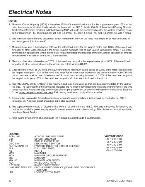
Electrical NotesNOTES:1. Minimum Circuit Ampacity (MCA) is based on 125% of the rated load amps for the largest motor plus 100% of therated load amps for all other loads included in the circuit, per N.E.C. Article 430‐24. If the optional Factory MountedControl Transformer is provided, add the following MCA values to the electrical tables for the system providing powerto the transformer: ‐17, add 2.5 amps; ‐28, add 2.3 amps; ‐40, add 1.5 amps, ‐46, add 1.3 amps; ‐58, add 1 amps.2. The minimum recommended disconnect switch is based on 115% of the rated load amps for all loads included inthe circuit, per N.E.C. Article 440.3. Minimum fuse size is based upon 150% of the rated load amps for the largest motor plus 100% of the rated loadamps for all other loads included in the circuit to avoid nuisance trips at start‐up due to lock rotor amps. It is not recommendedin applications where brown outs, frequent starting and stopping of the unit, and/or operation at ambienttemperatures in excess of 95ºF (35ºC) is anticipated.4. Maximum fuse size is based upon 225% of the rated load amps for the largest motor plus 100% of the rated loadamps for all other loads included in the circuit, per N.E.C. Article 440-22.5. Circuit breakers must be UL listed and CSA certified and maximum size is based on 225% of the rated load amps forthe largest motor plus 100% of the rated load amps for all other loads included in the circuit. Otherwise, HACR‐typecircuit breakers must be used. Maximum HACR circuit breaker rating is based on 225% of the rated load amps forthe largest motor plus 100% of the rated load amps for all other loads included in the circuit.6. The “INCOMING WIRE RANGE” is the minimum and maximum wire size that can be accommodated by the unit wiringlugs. The (2) preceding the wire range indicates the number of termination points available per phase of the wirerange specified. Actual wire size and number of wires per phase must be determined based on the National ElectricalCode, using copper connectors only. Field wiring must also comply with local codes.7. A ground lug is provided for each compressor system to accommodate a field grounding conductor per N.E.C.Table 250‐95. A control circuit grounding lug is also supplied.8. The supplied disconnect is a “Disconnecting Means” as defined in the N.E.C. 100, and is intended for isolating theunit for the available power supply to perform maintenance and troubleshooting. This disconnect is not intended tobe a Load Break Device.9. Field Wiring by others which complies to the National Electrical Code & Local Codes.LEGENDACR-LINEC.B.D.E.DISC SWFACT MOUNT CBFLAHZMAXMCAMINMIN NFRLAS.P. WIREUNIT MTD SERV SWLRAACROSS THE LINE STARTCIRCUIT BREAKERDUAL ELEMENT FUSEDISCONNECT SWITCHFACTORY MOUNTED CIRCUIT BREAKERFULL LOAD AMPSHERTZMAXIMUMMINIMUM CIRCUIT AMPACITYMINIMUMMINIMUM NON FUSEDRATED LOAD AMPSSINGLE POINT WIRINGUNIT MOUNTED SERVICE (NON-FUSED DISCONNECTSWITCH)LOCKED ROTOR AMPSVoltage Code-17 = 200-3-60-28 = 230-3-60-40 = 380-3-60-46 = 460-3-60-58 = 575-3-6040 jOHNSON CONTROLS


