

endof-
Signals & Systems Front Cover FOURTH.qxp - Orchard Publications
Signals & Systems Front Cover FOURTH.qxp - Orchard Publications

Create successful ePaper yourself
Turn your PDF publications into a flip-book with our unique Google optimized e-Paper software.
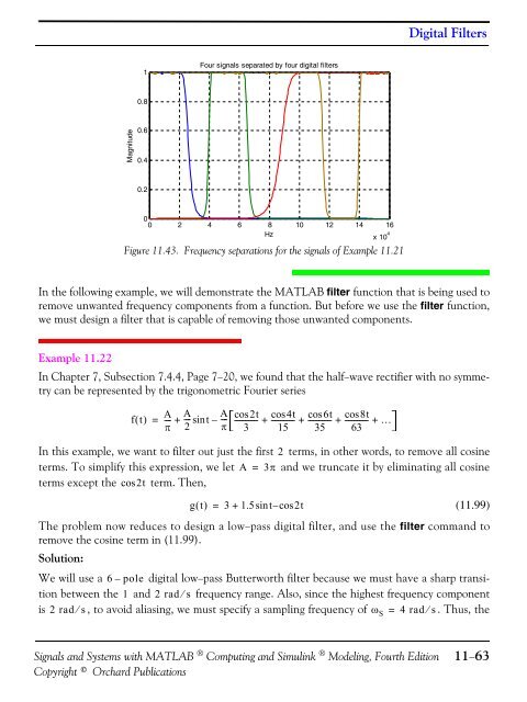
Digital Filters1Four signals separated by four digital filters0.8Magnitude0.60.40.200 2 4 6 8Hz10 12 14 16x 10 4Figure 11.43. Frequency separations for the signals of Example 11.21In the following example, we will demonstrate the MATLAB filter function that is being used toremove unwanted frequency components from a function. But before we use the filter function,we must design a filter that is capable of removing those unwanted components.Example 11.22In Chapter 7, Subsection 7.4.4, Page 7−20, we found that the half−wave rectifier with no symmetrycan be represented by the trigonometric Fourier seriesft ()=A---π+A--- sint2–A---πcos2t-------------3cos4t cos6t cos8t+ ------------- + ------------- + ------------- + …15 35 63In this example, we want to filter out just the first 2 terms, in other words, to remove all cosineterms. To simplify this expression, we let A = 3π and we truncate it by eliminating all cosineterms except the cos2t term. Then,gt () = 3+1.5sint–cos2t(11.99)The problem now reduces to design a low−pass digital filter, and use the filter command toremove the cosine term in (11.99).Solution:We will use a 6–pole digital low−pass Butterworth filter because we must have a sharp transitionbetween the 1 and 2 rad⁄s frequency range. Also, since the highest frequency componentis 2 rad ⁄ s, to avoid aliasing, we must specify a sampling frequency of ω S = 4 rad ⁄ s. Thus, theSignals and Systems with MATLAB ® Computing and Simulink ® Modeling, Fourth EditionCopyright © Orchard Publications11−63


