On-Board Type (DC) EMI Suppression Filters (EMIFILr)
On-Board Type (DC) EMI Suppression Filters ("EMIFIL")
On-Board Type (DC) EMI Suppression Filters ("EMIFIL")
- No tags were found...

Create successful ePaper yourself
Turn your PDF publications into a flip-book with our unique Google optimized e-Paper software.
!Note • This !Note PDF catalog • Please is downloaded read rating and from !CAUTION the website (for of Murata storage, Manufacturing operating, rating, co., ltd. soldering, Therefore, mounting it’s specifications and handling) are in subject this catalog to change to prevent or our smoking products and/or in it may burning, be discontinued etc. without advance notice. Please check with our<br />
sales representatives • This catalog or product has only engineers typical specifications before ordering. because there is no space for detailed specifications. Therefore, please approve our product specifications or transact the approval sheet for product specifications before ordering.<br />
• This PDF catalog has only typical specifications because there is no space for detailed specifications. Therefore, please approve our product specifications or transact the approval sheet for product specifications before ordering.<br />
C31E.pdf<br />
08.9.1<br />
Continued from the preceding page.<br />
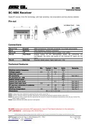
<strong>EMI</strong>FILr (Soldering and Mounting)<br />
Land Pattern<br />
+ Solder Resist<br />
Land Pattern<br />
Through Hole<br />
(in mm)<br />
BNX022<br />
BNX023<br />
12.5<br />
10.2<br />
9.9<br />
9.6<br />
7.1<br />
6.2<br />
5.3<br />
2.8<br />
2.3<br />
0<br />
B<br />
PSG<br />
CG<br />
CG<br />
CB<br />
CG<br />
(1) A double-sided print board (or multilayer board) as shown in<br />
the left figure is designed, and please apply a soldering Cu<br />
electrode with a product electrode to a "Land Pattern", apply<br />
resist to a "Land Pattern + Solder Resist" at Cu electrode.<br />
(2) Please drop CG on a ground electrode on the back layer<br />
(the same also in a multilayer case) by the through hole. And<br />
a surface grand electrode layer may also take a large area<br />
as much as possible.<br />
(3) It is recommended to use a double-sided printed circuit<br />
board with BNX mounting on one side and the ground<br />
pattern on the other in order to maximize filtering<br />
performance, multiple feed through holes are required to<br />
maximize the BNX's connection to ground.<br />
(4) The ground pattern should be designed to be as large as<br />
possible to achieve maximum filtering performance.<br />
0<br />
3.8<br />
5.8<br />
10.3<br />
13.2<br />
13.7<br />
17.5<br />
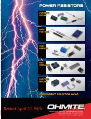
2. Solder Paste Printing and Adhesive Application<br />
When reflow soldering the chip <strong>EMI</strong> suppression filter, the<br />
printing must be conducted in accordance with the<br />
following cream solder printing conditions.<br />
If too much solder is applied, the chip will be prone to<br />
damage by mechanical and thermal stress from the PCB<br />
and may crack.<br />
Standard land dimensions should be used for resist and<br />
copper foil patterns.<br />
When flow soldering the <strong>EMI</strong> suppression filter, apply the<br />
adhesive in accordance with the following conditions.<br />
If too much adhesive is applied, then it may overflow into<br />
the land or termination areas and yield poor solderability.<br />
In contrast, if insufficient adhesive is applied, or if the<br />
adhesive is not sufficiently hardened, then the chip may<br />
become detached during flow soldering process.<br />
(in mm)<br />
Series Solder Paste Printing Adhesive Application<br />
BLM<br />
(Except BLM<br />
15A_AN series)<br />
oEnsure that solder is applied smoothly to a<br />
minimum height of 0.2mm to 0.3mm at the end<br />
surface of the part.<br />
oCoat with solder paste to the following thickness:<br />
50-80µm: BLM02<br />
100-150µm: BLM03<br />
100-200µm: BLM15/18/21/31/41<br />
Coating amount is illustrated in the<br />
following diagram.<br />
Chip Solid Inductor<br />
a: 20−70µm<br />
b: 30−35µm<br />
c: 50−105µm<br />
a<br />
0.2−0.3mm min.<br />
PCB<br />
Bonding agent<br />
Land<br />
b<br />
c<br />
BLA<br />
oUse Sn/Pb=60/40 or Sn-3.0Ag-0.5Cu solder for<br />
pattern printing. Use of Sn-Zn based solder will<br />
deteriorate performance of products. In case of<br />
using Sn-Zn based solder, please contact Murata<br />
in advance.<br />
oCoat with solder paste to the following thickness:<br />
100-150µm: BLA2A<br />
150-200µm: BLA31<br />
BLA31 Series only<br />
Coating amount is illustrated in the<br />
following diagram.<br />
Chip Solid Inductor<br />
a: 20−70µm<br />
b: 30−35µm<br />
c: 50−105µm<br />
a<br />
c<br />
6<br />
BLA31<br />
0.4<br />
BLA2A<br />
1.75<br />
PCB<br />
Bonding agent<br />
Land<br />
b<br />
0.8<br />
0.7 0.8 0.7<br />
0.5 0.5 0.5<br />
0.25 0.25<br />
1.5<br />
Continued on the following page.<br />
181