On-Board Type (DC) EMI Suppression Filters (EMIFILr)
On-Board Type (DC) EMI Suppression Filters ("EMIFIL")
On-Board Type (DC) EMI Suppression Filters ("EMIFIL")
- No tags were found...

You also want an ePaper? Increase the reach of your titles
YUMPU automatically turns print PDFs into web optimized ePapers that Google loves.
t<br />
Minimum Quantity (Pcs.)<br />
Series Bulk<br />
Ammo Pack<br />
BL01RN<br />
BL02RN<br />
BL03RN<br />
500<br />
500<br />
1000<br />
1000<br />
1500<br />
2000<br />
ø320mm Paper reel<br />
2000<br />
—<br />
—<br />
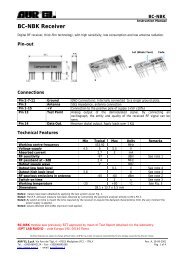
BL01RN_J<br />
BL01RN_A<br />
0 max.<br />
Direction of feed<br />
ø3.6<br />
±0.15<br />
5±0.3<br />
0.8 max. L1 L2<br />
ø0.60±0.05<br />
5±0.5<br />
I<br />
1.2 max.<br />
3.2 min.<br />
0.8 max.<br />
BL02RN1R2p1A<br />
W<br />
t<br />
W1<br />
L<br />
P1<br />
P2<br />
F<br />
P<br />
7.5 max.<br />
7.5 max.<br />
∗<br />
W2<br />
H1<br />
W0<br />
3.4±0.2<br />
ød<br />
∆S<br />
∆h1<br />
∆h2<br />
*L<br />
6.0±1.0<br />
| L1 - L2 | V 1.5<br />
*L BL01RN1A1F1J : 52+2/-1<br />
BL01RN1A1E1A : 26+1.5/-0<br />
D0<br />
P0<br />
∗There is an excess bond stick on the wire.<br />
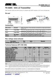
BL02RN1R3N1A<br />
P<br />
12.0 max.<br />
∗<br />
W2<br />
H1<br />
3.4±0.2<br />
ød<br />
∆S<br />
∆h1<br />
∆h2<br />
BL02RN2R1p1A<br />
W<br />
W1<br />
W0<br />
I<br />
P1<br />
P2<br />
F<br />
8.0 max.<br />
L<br />
t<br />
P<br />
7.5 max.<br />
W2<br />
H1<br />
3.4±0.2<br />
ød<br />
∆S<br />
∆h1<br />
∆h2<br />
W<br />
W1<br />
W0<br />
I<br />
P1<br />
P2<br />
F<br />
9.0 max.<br />
L<br />
t<br />
BL02RN2R3N1A<br />
D0<br />
P0<br />
∗There is an excess bond stick on the wire.<br />
BL03RN2R1p1A<br />
P0<br />
D0<br />
∆S<br />
P<br />
9.0 max.<br />
3.4±0.2<br />
12.0 max.<br />
W2<br />
H1<br />
ød<br />
∆h1<br />
∆h2<br />
W<br />
W1<br />
W0<br />
I<br />
P2<br />
P1<br />
F<br />
L<br />
t<br />
∆S<br />
P<br />
8.3 max.<br />
2.3 max.<br />
6.5 max.<br />
W2<br />
H1<br />
ød<br />
∆h1<br />
∆h2<br />
W<br />
W1<br />
W0<br />
I<br />
!Note • This !Note PDF catalog • Please is downloaded read rating and from !CAUTION the website (for of Murata storage, Manufacturing operating, rating, co., ltd. soldering, Therefore, mounting it’s specifications and handling) are in subject this catalog to change to prevent or our smoking products and/or in it may burning, be discontinued etc. without advance notice. Please check with our<br />
sales representatives • This catalog or product has only engineers typical specifications before ordering. because there is no space for detailed specifications. Therefore, please approve our product specifications or transact the approval sheet for product specifications before ordering.<br />
• This PDF catalog has only typical specifications because there is no space for detailed specifications. Therefore, please approve our product specifications or transact the approval sheet for product specifications before ordering.<br />
C31E.pdf<br />
08.9.1<br />
Ferrite Beads Inductors Packaging<br />
Taping Dimensions<br />
P2<br />
P1<br />
F<br />
L<br />
P0<br />
D0<br />
P0<br />
D0<br />
Description<br />
Symbol<br />
Dimension (mm)<br />
Remarks<br />
Pitch of component<br />
P<br />
12.7<br />
Product inclination ∆S determines tolerance<br />
Pitch of sprocket hole<br />
Lead spacing<br />
Hole center to lead<br />
P0<br />
F<br />
P1<br />
12.7±0.2<br />
+0.8<br />
5.0 -0.2<br />
3.85±0.7<br />
Hole center to component center<br />
P2<br />
6.35±1.3<br />
Tape deviation in feeding direction<br />
Offset of bead<br />
∆S<br />
±1.0<br />
Include the offset caused by lead bend<br />
Carrier tape width<br />
Position of sprocket hole<br />
Lead length between sprocket<br />
hole and forming position<br />
W<br />
W1<br />
H1<br />
18.0±0.5<br />
+0<br />
9.0 -0.5 0.0<br />
Lead Length Number : N<br />
Lead Length Number : Q<br />
Lead Length Number : P<br />
16.5±0.5<br />
20.0±0.5<br />
18.5±0.5<br />
Tape with deviation<br />
BL02, BL03<br />
BL02RN1R2/2R1, BL03<br />
BL02, BL03<br />
6<br />
Protruding length<br />
I<br />
+0.5 to –1.0<br />
Diameter of sprocket hole<br />
D0<br />
ø4.0±0.1<br />
Lead Diameter<br />
ød<br />
ø0.60<br />
Total tape thickness<br />
t<br />
0.7±0.2<br />
Including bonding tape thickness<br />
Deviation across tape, Deviation across tape rear<br />
Cutting position of failure<br />
Hold down tape width<br />
∆h1, ∆h2<br />
L<br />
W0<br />
1.0 max.<br />
+0<br />
11.0 -1.0 0.0<br />
12.0±0.5<br />
Hold down tape position<br />
W2<br />
1.5±1.5<br />
(in mm)<br />
193