2-wire Relay (KO Mount) WR-6221K-82 Technical Data noncondensing
KO Mount Relays and Panels - Douglas Lighting Control
KO Mount Relays and Panels - Douglas Lighting Control
- No tags were found...

Create successful ePaper yourself
Turn your PDF publications into a flip-book with our unique Google optimized e-Paper software.
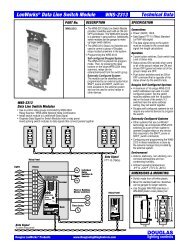
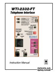
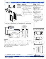
2-<strong>wire</strong> <strong>Relay</strong> (<strong>KO</strong> <strong>Mount</strong>)<br />
PART No.<br />
<strong>WR</strong>-<strong>6221K</strong>-<strong>82</strong><br />
16 Amp Rated<br />
<strong>KO</strong> <strong>Relay</strong><br />
DESCRIPTION<br />
<strong>WR</strong>-<strong>6221K</strong>-<strong>82</strong><br />
<br />
Knockout mount relay, 1 pole.<br />
<br />
Branch circuit, 16 Ampere latching relay.<br />
<br />
Screw terminals on load side and colored<br />
pre-stripped leads on control side.<br />
<br />
Manual operation lever and indicator<br />
built-in for convenient operation and<br />
status check at the panel.<br />
<br />
<strong>Relay</strong> fits to standard 1/2 inch pipe knock<br />
out (7/8 in hole).<br />
<br />
Use Douglas WEx series relay panels<br />
(sizes 6, 12, 24, 36, 48, 60 and 72).<br />
NOTE: The <strong>WR</strong>-<strong>6221K</strong>-<strong>82</strong> <strong>Relay</strong> is<br />
identical to the <strong>WR</strong>-6221 <strong>Relay</strong> except<br />
for the 16A contact rating.<br />
<strong>Technical</strong> <strong>Data</strong><br />
SPECIFICATION<br />
Control Input<br />
<br />
Class 2 circuit<br />
<br />
0.350 A (350mA)<br />
<br />
24 volt reversible polarity pulse<br />
<br />
Input terminals: #16 - #20 AWG<br />
Output Contact Ratings<br />
<br />
More than 30,000 operations<br />
@20 times / min. switch speed.<br />
<br />
UL Listings<br />
16A 300 VAC<br />
1920 W 120 VAC Tungsten<br />
16A 300 VAC Ballast<br />
<br />
CSA Certifications<br />
16A 347 VAC<br />
1920 W 120 VAC Tungsten<br />
16A 347 VAC Ballast<br />
<br />
Output terminals: #12 - #14 AWG<br />
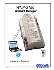
<strong>WR</strong>-<strong>6221K</strong>-<strong>82</strong> <strong>Relay</strong><br />
Manual Switch<br />
Lever<br />
Status<br />
Indicator<br />
Plastic<br />
<strong>Mount</strong>ing<br />
Nut<br />
Environment<br />
<br />
Indoors, stationary, non-vibrating,<br />
non-corrosive atmosphere and <strong>noncondensing</strong><br />
humidity.<br />
<br />
Ambient temperature:<br />
-20° to +120°F (-28° to +50°C)<br />
Load<br />
Terminals<br />
Low<br />
Voltage<br />
Wires<br />
DIMENSIONS & MOUNTING<br />
CONNECTIONS<br />
<br />
<strong>WR</strong>-<strong>6221K</strong>-<strong>82</strong> relays mount through a<br />
1/2" Knock out (7/8" hole). Douglas<br />
WEx series relay panels are made<br />
with barriers that have 1/2" <strong>KO</strong>'s<br />
suited to <strong>WR</strong>-<strong>6221K</strong>-<strong>82</strong> relays.<br />
<strong>WR</strong>-<strong>6221K</strong>-<strong>82</strong><br />
Lights<br />
H<br />
Breaker<br />
Tr<br />
24V<br />
<strong>Relay</strong>s<br />
White<br />
Blue<br />
Red<br />
Switches<br />
Sw<br />
Sw<br />
Lights<br />
H<br />
Breaker<br />
Tr<br />
24V<br />
<strong>Relay</strong>s<br />
White<br />
Blue<br />
Red<br />
Switches<br />
Sw<br />
1.97<br />
18" Wires<br />
Wire length NTS<br />
Limit of 6<br />
switches<br />
per relay.<br />
Sw<br />
Sw<br />
Sw<br />
Sw<br />
Limit of 4 relays<br />
per switch<br />
(Limit is 8 with<br />
<strong>WR</strong>-8001 Sw)<br />
1.46<br />
0.63<br />
1.85 1.14<br />
0.66<br />
Components 1.5<br />
A-1.5,6,7,8 -<strong>Relay</strong>s & Panels, <strong>KO</strong> <strong>Mount</strong><br />
www.DouglasLightingControls.com
2-<strong>wire</strong> <strong>Relay</strong> (<strong>KO</strong> <strong>Mount</strong>)<br />
<strong>WR</strong>-<strong>6221K</strong>-<strong>82</strong><br />
<strong>Technical</strong> <strong>Data</strong><br />
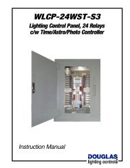
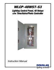
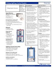
2-WIRE RELAY TECHNOLOGY<br />
Douglas 2-<strong>wire</strong> relays utilize an ingenious control method that<br />
permits simple and minimal wiring. All functions for low voltage<br />
control: on, off, indication and location are provided with<br />
only a 2-<strong>wire</strong> connection of which one is often a common. All<br />
Douglas relays manufactured over the past 35 years utilize the<br />
same principle. Thus, any Douglas switching device is<br />
compatible with any model of Douglas relay.<br />
Operational Principle<br />
A negative pulse turns the relay ON and a positive pulse turns it<br />
OFF. Using a diode, an AC signal can be rectified to turn the relay<br />
either ON or OFF. Douglas switches have 2 diodes built into the<br />
switch to provide the ON and OFF signals.<br />
The relay has 2 similar diodes built inside that are in series with the<br />
relay coil. The diodes in the relay act as gates for the switch signal.<br />
To turn the relay ON or OFF, the rocker switch completes the circuit<br />
by selecting the ON or OFF diode. If the diode selected is in the<br />
same direction as the gate diode in the relay, the relay will switch. If<br />
the gate diode is not in the correct direction, then nothing will<br />
happen since the relay is already in the correct state for the action<br />
selected by the switch. When the switch is released, a spring returns<br />
it to the central neutral position.<br />
Indication (ON state) and location (OFF state) are obtained by<br />
utilizing LED diodes built into the switch. Only the LED which is<br />
connected in the same direction as the gate diode in the relay will<br />
light. Although the LED current passes through the relay coil, it is<br />
not large enough to cause the relay to trip. However, there is a limit:<br />
the maximum number of LED switches that can be connected to the<br />
same relay is 6.<br />
For additional convenience (especially during installation) all standard<br />
models have a manual control lever and indicator permitting a nonelectrical<br />
method of switching and status check at the panel.<br />
Manual<br />
Lever<br />
Detailed 2-<strong>wire</strong> <strong>Relay</strong> / Switch Circuit<br />
Transformer<br />
24VAC<br />
W<br />
B<br />
Latch to lock relay ON<br />
or OFF (actually done<br />
with magnetics)<br />
Tr<br />
W<br />
B<br />
<strong>Relay</strong><br />
Blue<br />
2-<strong>wire</strong><br />
<strong>Relay</strong><br />
Red<br />
Gate Diodes<br />
<strong>Relay</strong> Coil<br />
White<br />
2-<strong>wire</strong> Switch<br />
Switch<br />
Control Diodes<br />
Switch<br />
Switching ON<br />
Switch pressed to ON position.<br />
ON pulse ( ) sent to relay and<br />
relay begins to switch over to ON.<br />
Tr<br />
W<br />
B<br />
Switch<br />
Detailed LED Switch Circuit *<br />
Transformer<br />
24VAC<br />
W<br />
B<br />
Blue<br />
White<br />
LED 2-<strong>wire</strong> Switch<br />
ON<br />
ON<br />
<strong>Relay</strong><br />
Switched ON<br />
<strong>Relay</strong> completed switching to ON position.<br />
OFF gate diode engaged and ON pulse<br />
from switch is stopped by OFF gate diode.<br />
<strong>Relay</strong> ready for OFF pulse.<br />
2-<strong>wire</strong> <strong>Relay</strong><br />
Red<br />
Gate Diodes<br />
<strong>Relay</strong> Coil<br />
OFF<br />
OFF<br />
Control<br />
Diodes<br />
LED<br />
Indicator Diodes<br />
Current limiting<br />
Resistor<br />
Tr<br />
W<br />
B<br />
Switch<br />
*<br />
LED Switch circuit actually not<br />
as shown. Switch is functionally<br />
similar except rocker switch is<br />
replaced with single push button.<br />
<strong>Relay</strong><br />
Switching OFF<br />
Switch pressed to OFF position.<br />
OFF pulse ( ) sent to relay and<br />
relay begins to switch over to OFF.<br />
Components 1.6 1.1<br />
www.DouglasLightingControls.com<br />
lighting controls<br />
A-1.5,6,7,8 -<strong>Relay</strong>s & Panels, <strong>KO</strong> <strong>Mount</strong>
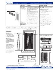
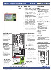
<strong>Relay</strong> Panels for <strong>KO</strong> <strong>Mount</strong> <strong>Relay</strong>s<br />
WEx Panels<br />
<strong>Technical</strong> <strong>Data</strong><br />
PART No.<br />
WEx Panels<br />
DESCRIPTION<br />
<br />
Douglas WEx series relay panels are a<br />
versatile line of panels used for <strong>WR</strong>-<br />
<strong>6221K</strong>-<strong>82</strong> <strong>KO</strong> mount relays.<br />
<br />
Standard sizes range from 6 to 72<br />
relays.<br />
<br />
A barrier is provided to separate the line<br />
and low voltage areas of the panel. The<br />
barrier has knock outs and is specially<br />
shaped for mounting <strong>WR</strong>-<strong>6221K</strong>-<strong>82</strong><br />
relays and the transformer.<br />
<br />
A DIN rail is installed in the center of the<br />
enclosure. The DIN rail provides<br />
mounting for optional controls.<br />
<br />
Enclosure walls have knockouts located<br />
so that panels of same horizontal or<br />
vertical dimension can be joined with<br />
conduit nipples.<br />
<br />
Panels that have hinged covers have a<br />
lockable latch.<br />
SPECIFICATION<br />
<br />
Enclosures, barriers and covers are<br />
made of steel coated with ANSI/ASA<br />
61 Grey. Coating is a heat fused,<br />
polyester epoxy finish applied on all<br />
surfaces.<br />
Certifications<br />
<br />
UL listed, CSA approved<br />
<br />
EEMAC/NEMA 1 Standard<br />
Options<br />
<br />
Hinged, surface or flush covers. Covers<br />
are reversible for either left-to-right or<br />
right-to-left door opening.<br />
<br />
Driphoods (surface mount only).<br />
<br />
Voltage barriers to divide line voltage<br />
compartment for different line voltages.<br />
WEx Panel Numbering System<br />
Enclosure<br />
WEx<br />
Barrier<br />
C<br />
xx<br />
W<br />
B<br />
S1<br />
F2<br />
Cover<br />
or<br />
S3<br />
F4<br />
5.7"<br />
Box Code Capacity<br />
Barrier Layout <strong>Relay</strong> Code<br />
Compartment: C <strong>WR</strong>-6221: B<br />
Wireway: W<br />
Screw-on<br />
Surface: S1<br />
Flush: F2<br />
Hinged<br />
Surface: S3<br />
Flush: F4<br />
5"<br />
5"<br />
5.7"<br />
5.7"<br />
Compartment Style<br />
Barrier Layout<br />
CAPACITY<br />
PART No.<br />
SIZE (H x W x D)<br />
4.5"<br />
5"<br />
6"<br />
7.5"<br />
8.5"<br />
6 12 24 36 48 60<br />
WE0 - C06B - ** WE1 - C12B - ** WE2 - C24B - ** WE3 - C36B - ** WE4 - C48B - ** WE6 - C60B - **<br />
12 x 12 x 4.25 20 x 14 x 4.25 33 x 14 x 4.25 27 x 20 x 4.25 33 x 20 x 4.25 39 x 20 x 4.25<br />
** Add cover style number at end of P/N<br />
4"<br />
6"<br />
5.7"<br />
4.9"<br />
4.9"<br />
4.9"<br />
Symbols<br />
Low voltage area<br />
Line voltage area<br />
<strong>WR</strong>-6221 relay<br />
Transformer<br />
Wireway Style<br />
Barrier Layout<br />
CAPACITY<br />
PART No.<br />
SIZE (H x W x D)<br />
4"<br />
5.7" 6"<br />
5.7" 5.7" 5.7"<br />
24<br />
36 48 72<br />
WE3 - W24B - ** WE4 - W36B - ** WE6 - W48B - ** WE8 - W72B - **<br />
27 x 20 x 4.25 33 x 20 x 4.25 39 x 20 x 4.25 54 x 20 x 4.25<br />
Components 1.7<br />
A-1.5,6,7,8 -<strong>Relay</strong>s & Panels, <strong>KO</strong> <strong>Mount</strong><br />
www.DouglasLightingControls.com
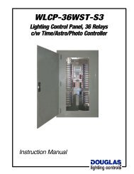
<strong>Relay</strong> Panels for <strong>KO</strong> <strong>Mount</strong> <strong>Relay</strong>s<br />
WEx Panels<br />
<strong>Technical</strong> <strong>Data</strong><br />
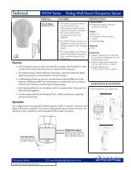
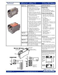
WEx Panels: Exploded View<br />
Drip Shields<br />
Optional, surface cover<br />
panels only.<br />
Enclosure & Barriers<br />
Enclosures are supplied with<br />
barriers installed in either the<br />
compartment or <strong>wire</strong>way format.<br />
(See drawing below)<br />
<strong>Relay</strong>s & transformers mount<br />
thru 1/2" <strong>KO</strong>'s in barrier.<br />
Barrier is of special shape to<br />
accommodate <strong>WR</strong>-<strong>6221K</strong>-<strong>82</strong> relay.<br />
Hinged Covers<br />
Surface (S3) or Flush (F4).<br />
Install right side up or upside down<br />
for right-to-left or left-to-right door.<br />
Cover latch can be locked if desired.<br />
The trim of the hinged cover covers<br />
over some of the line voltage wiring.<br />
A space is left open for access to the<br />
relay's manual control levers.<br />
Screw-on<br />
Covers<br />
Surface (S1) or<br />
Flush (F2)<br />
Stacking Panels<br />
Panels of equal dimension on a<br />
side have matching <strong>KO</strong> pattern<br />
to provide easy stacking.<br />
INSTALLATION & ASSEMBLY<br />
WEx series relay panels for <strong>WR</strong>-<strong>6221K</strong>-<strong>82</strong> <strong>KO</strong> mount relay are<br />
supplied with steel barrier(s) installed inside of the enclosure.<br />
The barrier(s) have 1/2" knock outs that are used to mount the<br />
transformer and <strong>WR</strong>-<strong>6221K</strong>-<strong>82</strong> relays.<br />
WEx panels are primarily intended for field installation of relays<br />
and controls. WEx panels generally are not factory preassembled.<br />
To install the relay panel the following sequence is<br />
recommended:<br />
1) <strong>Mount</strong> the panel onto the wall and pull <strong>wire</strong>s. It is<br />
recommended that all (or most) of the <strong>wire</strong>s be pulled prior to<br />
installing any relays or other components. This will prevent<br />
component damage from the <strong>wire</strong> pulling operation.<br />
2) <strong>Relay</strong> line voltage terminals are sized for a maximum of<br />
12AWG <strong>wire</strong>.<br />
For low voltage wiring 18AWG solid is recommended.<br />
3) Once the <strong>wire</strong>s have been pulled, install relays into <strong>KO</strong>'s.<br />
Make line connections to relays. To test circuit, turn circuit<br />
breaker off, use manual lever to turn relay on and then turn on<br />
the circuit breaker. This will help prevent relay contact welding<br />
due to dead shorts.<br />
4) Record which circuit the relay operates. Use blank panel<br />
schedule provided.<br />
5) Once the line circuits are connected and identified, install and<br />
<strong>wire</strong> low voltage controls (relay scanners, etc).<br />
Compartment<br />
Format<br />
Wireway<br />
Style Layout<br />
Components 1.8<br />
A-1.5,6,7,8 -<strong>Relay</strong>s & Panels, <strong>KO</strong> <strong>Mount</strong><br />
www.DouglasLightingControls.com