Programmable Relay Scanner WRS-2224 Technical Data noncorrosive noncondensing
Programmable Relay Scanner - Douglas Lighting Control
Programmable Relay Scanner - Douglas Lighting Control
- No tags were found...

You also want an ePaper? Increase the reach of your titles
YUMPU automatically turns print PDFs into web optimized ePapers that Google loves.
OPTIONS<br />
PROGRAM<br />
MODE<br />
NORMAL<br />
MODE<br />
INPUT<br />
SELECT<br />
ON<br />
OVERRIDE<br />
OFF<br />
OVERRIDE<br />
<strong>Programmable</strong> <strong>Relay</strong> <strong>Scanner</strong><br />
<strong>WRS</strong>-<strong>2224</strong><br />
<strong>Technical</strong> <strong>Data</strong><br />
PART No.<br />
DESCRIPTION<br />
SPECIFICATION<br />
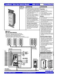
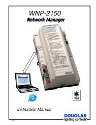
<strong>Relay</strong> Outputs<br />
24 output terminals (12 per side),<br />
are provided for relay control.<br />
Douglas 2-wire switches can be<br />
connected in parallel to permit<br />
individual control of a relay by<br />
switch.<br />
Individual Output LED's<br />
In operating mode, LEDs display<br />
if the relay is ON or OFF.<br />
In programming mode, LEDs<br />
display if relay is included in the<br />
group being programmed to a<br />
master input.<br />
Select Buttons<br />
& LED's for:<br />
1) Operating mode<br />
2) Program mode<br />
3) Flick Warn or Time Out Option<br />
Directions<br />
Directions are printed on keypad<br />
for handy user reference.<br />
Direct Digital Control Socket<br />
Addressable RS-485, Lonworks and<br />
BACnet network communication<br />
modules are available.<br />
<strong>WRS</strong>-<strong>2224</strong><br />
24 <strong>Relay</strong><br />
<strong>Programmable</strong><br />
<strong>Scanner</strong><br />
<strong>WRS</strong>-<strong>2224</strong><br />
<strong>Programmable</strong><br />
<strong>Relay</strong> <strong>Scanner</strong><br />
<br />
<strong>Relay</strong> scanners have wide application in<br />
low voltage lighting controls. <strong>Relay</strong><br />
scanners permit a large group of relays<br />
to be switched together. <strong>Relay</strong> scanners<br />
also permit each relay in the group to<br />
be individually switched.<br />
<br />
<strong>WRS</strong>-<strong>2224</strong> programmable scanners<br />
can assign relay groups with a built in<br />
keypad. Instructions are on the label of<br />
the scanner. Five relay groups are<br />
possible.<br />
<br />
Each of the 5 relay groups can have a<br />
flick warn option selected to warn<br />
occupants of an off sweep. After the<br />
flick warning, occupants can cancel the<br />
off signal with an override switch.<br />
<br />
Each of the 5 relay groups can have a<br />
time out option selected to automatically<br />
start a timer when a group relay is<br />
switched on then turn all group relays<br />
off when the timer expires.<br />
Individual Output<br />
Buttons<br />
In operating mode, use<br />
buttons to switch the<br />
connected relay ON or OFF.<br />
In programming mode, use<br />
buttons to enter or remove<br />
the relay from the group<br />
being programmed.<br />
Master Switch<br />
Override Buttons<br />
Use ON and OFF<br />
override buttons to<br />
switch relay groups.<br />
Use input select button<br />
to choose a relay group.<br />
Input Select Button<br />
Use the input select button<br />
to select the relay group<br />
and master inputs 1, 2, 3,<br />
4 or 5.<br />
5 Master Switch Inputs<br />
Connect Douglas 2-wire relay<br />
switches to master inputs to switch<br />
relay groups ON and OFF.<br />
Up to 3 switches and/or 2-wire<br />
timer outputs can be connected to<br />
the same master switch input.<br />
<br />
Power:<br />
24VAC / 50mA<br />
Class 2 Low Voltage device.<br />
Power rating does not include power<br />
used to switch relays.<br />
<br />
There are 5 master switch inputs that<br />
are compatible with all models of Douglas<br />
relay switches. Max. wire length for a<br />
master switch is 2000' (600m).<br />
<br />
<strong>Programmable</strong> scanners have a digital<br />
link socket that permits connection of<br />
network communication modules.<br />
Outputs<br />
<br />
<strong>WRS</strong>-<strong>2224</strong>: 24 Douglas relay outputs.<br />
<br />
Outputs fire in sequence (
OPTIONS<br />
PGM<br />
MODE<br />
NORMAL<br />
MODE<br />
INPUT<br />
SELECT<br />
ON<br />
OVERRIDE<br />
OFF<br />
OVERRIDE<br />
<strong>Programmable</strong> <strong>Relay</strong> <strong>Scanner</strong><br />
<strong>WRS</strong>-<strong>2224</strong><br />
<strong>Technical</strong> <strong>Data</strong><br />
Office Floor -Reflected Ceiling Plan<br />
Office<br />
Sw<br />
Office<br />
Office<br />
Sw<br />
Office<br />
Office<br />
Sw<br />
Hall<br />
Sw<br />
Office<br />
Sw<br />
Office<br />
NW Quadrant<br />
Reception<br />
Office<br />
Hall<br />
SW Quadrant<br />
Sw<br />
Office Office Office<br />
Library<br />
Core<br />
Mens<br />
Womens<br />
Hall<br />
Hall<br />
Hall<br />
Storage<br />
Elevator<br />
Photo<br />
Copy<br />
NE Quadrant<br />
Office<br />
Office<br />
Office<br />
SE Quadrant<br />
Hall<br />
Office<br />
Office<br />
Office<br />
Office<br />
Office<br />
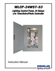
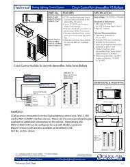
CONNECTIONS<br />
Simple Stand Alone Panels<br />
<strong>Relay</strong> scanners permit a group of relays to be controlled with<br />
a single master switch. Individual relays of the relay group<br />
can also be individually switched.<br />
<strong>Programmable</strong> relay scanners can control several relay<br />
groups. Use the keypad built into the front of the scanner to<br />
assign the relay groups. Connect the master switches or<br />
automation controls to the scanner's inputs. Changes to relay<br />
groups are easy to accomplish with the keypad, no rewiring<br />
is necessary.<br />
Timer automation will yield significant energy savings. A<br />
common application is to program a timer to send an OFF<br />
signal periodically during the unoccupied hours.<br />
Install wall switches to provide for occupant override. This<br />
can be either individual switches connected directly to the<br />
relays and/or master switches connected to the scanner.<br />
The scanner can be set to provide a "Flick Warn before<br />
OFF". When a timer signals the scanner OFF, the flick warn<br />
sequence occurs. See section titled "FLICK WARN BEFORE<br />
OFF" for more details.<br />
<br />
Zones<br />
The scanner can also set a "Time Out" period where any<br />
lights left ON will be automatically turned off at the end of<br />
the period.<br />
NW Quadrant NE Quadrant<br />
Core<br />
SW Quadrant SE Quadrant<br />
Office Office Office Office Office Office<br />
Individual<br />
Switches<br />
White<br />
Group 1<br />
<strong>Relay</strong> #<br />
1<br />
2<br />
Lighting Circuit<br />
NW Priv Office<br />
NW Priv Office<br />
<strong>Relay</strong>s<br />
1<br />
2<br />
3<br />
4<br />
5<br />
6<br />
7<br />
8<br />
9<br />
10<br />
11<br />
12<br />
Outputs<br />
1<br />
2<br />
3<br />
4<br />
5<br />
6<br />
7<br />
8<br />
9<br />
10<br />
11<br />
12<br />
13<br />
14<br />
15<br />
16<br />
17<br />
18<br />
19<br />
20<br />
21<br />
22<br />
23<br />
24<br />
13<br />
14<br />
15<br />
16<br />
17<br />
18<br />
19<br />
20<br />
21<br />
22<br />
23<br />
24<br />
<strong>Relay</strong> Panel<br />
Transformer<br />
W<br />
B 24VAC<br />
<strong>Relay</strong>s<br />
Group<br />
Switch<br />
Station<br />
3<br />
4<br />
5<br />
6<br />
NW Priv Office<br />
Library<br />
NW Priv Office<br />
NW Priv Office<br />
<strong>WRS</strong>-<strong>2224</strong><br />
<strong>Relay</strong><br />
<strong>Scanner</strong><br />
Inputs<br />
W B<br />
1<br />
2<br />
3<br />
B 45<br />
B<br />
WTP-4408<br />
Time Clock<br />
NW<br />
Quad<br />
SW<br />
Quad<br />
NE<br />
Quad<br />
SE<br />
Quad<br />
Core<br />
Core<br />
Core<br />
A B C D<br />
1 2 3<br />
1 2 3<br />
Esc<br />
4 5 6<br />
4 58 69<br />
7<br />
0 7 8 9<br />
0<br />
5 A I H<br />
5 A I H<br />
Clr<br />
9<br />
<br />
!<br />
"#$%&<br />
9<br />
*<br />
W<br />
24VAC<br />
Power<br />
Interfaces 2.2<br />
C-2-1,2,3,4 -Controls, Pgm <strong>Scanner</strong><br />
www.DouglasLightingControls.com
OPTIONS<br />
OPTIONS<br />
1<br />
2<br />
3<br />
4<br />
5<br />
6<br />
7<br />
8<br />
9<br />
10<br />
11<br />
12<br />
1<br />
2<br />
3<br />
4<br />
5<br />
6<br />
7<br />
8<br />
9<br />
10<br />
11<br />
12<br />
PG M<br />
MODE<br />
PG M<br />
MODE<br />
1<br />
2<br />
3<br />
4<br />
5<br />
6<br />
7<br />
8<br />
9<br />
10<br />
11<br />
12<br />
NORMAL<br />
MODE<br />
1<br />
2<br />
3<br />
4<br />
5<br />
6<br />
7<br />
8<br />
9<br />
10<br />
11<br />
12<br />
NORMAL<br />
MODE<br />
13<br />
14<br />
15<br />
16<br />
17<br />
18<br />
19<br />
20<br />
21<br />
22<br />
23<br />
24<br />
INPUT<br />
SELECT<br />
13<br />
14<br />
15<br />
16<br />
17<br />
18<br />
19<br />
20<br />
21<br />
22<br />
23<br />
24<br />
INPUT<br />
SELECT<br />
13<br />
14<br />
15<br />
16<br />
17<br />
18<br />
19<br />
20<br />
21<br />
22<br />
23<br />
24<br />
ON<br />
OVERRIDE<br />
OFF<br />
OVERRIDE<br />
1<br />
2<br />
13<br />
14<br />
15<br />
16<br />
17<br />
18<br />
19<br />
20<br />
21<br />
22<br />
23<br />
24<br />
ON<br />
OVERRIDE<br />
OFF<br />
OVERRIDE<br />
1<br />
2<br />
OPTIONS<br />
1<br />
2<br />
3<br />
4<br />
5<br />
6<br />
7<br />
8<br />
9<br />
10<br />
11<br />
12<br />
PG M<br />
MODE<br />
1<br />
2<br />
3<br />
4<br />
5<br />
6<br />
7<br />
8<br />
9<br />
10<br />
11<br />
12<br />
NORMAL<br />
MODE<br />
13<br />
14<br />
15<br />
16<br />
17<br />
18<br />
19<br />
20<br />
21<br />
22<br />
23<br />
24<br />
INPUT<br />
SELECT<br />
13<br />
14<br />
15<br />
16<br />
17<br />
18<br />
19<br />
20<br />
21<br />
22<br />
23<br />
24<br />
ON<br />
OVERRIDE<br />
OFF<br />
OVERRIDE<br />
1<br />
2<br />
OPTIONS<br />
OPTIONS<br />
PGM<br />
MODE<br />
PGM<br />
MODE<br />
NORMAL<br />
MODE<br />
NORMAL<br />
MODE<br />
INPUT<br />
SELECT<br />
INPUT<br />
SELECT<br />
ON<br />
OVERRIDE<br />
OFF<br />
OVERRIDE<br />
ON<br />
OVERRIDE<br />
OFF<br />
OVERRIDE<br />
<strong>Programmable</strong> <strong>Relay</strong> <strong>Scanner</strong><br />
<strong>WRS</strong>-<strong>2224</strong><br />
<strong>Technical</strong> <strong>Data</strong><br />
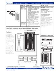
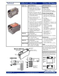
CONNECTIONS<br />
Multiple <strong>Relay</strong> Panels<br />
In larger buildings, there are often several load centers that<br />
need to be controlled from one location.<br />
A simple wiring strategy is to interconnect the relay panels<br />
with a multi-conductor bus. This method permits several<br />
master switch controls to exist at each relay panel. Connect<br />
the scanners in the relay panel to the appropriate control<br />
wire of the bus.<br />
Projects that are interconnected with a multi-conductor bus<br />
should use a separate transformer to supply the power<br />
used by the multi-conductor bus. Therefore, the power used<br />
in each relay panel to switch the relays is separate from the<br />
power used for the master switching circuit. The isolation of<br />
the panel power from the signal power is in the relay<br />
scanner. All Douglas scanners have optically isolated<br />
master switch inputs.<br />
The <strong>WRS</strong>-<strong>2224</strong> <strong>Programmable</strong> <strong>Relay</strong> <strong>Scanner</strong> can be<br />
networked with a data signal to other <strong>WRS</strong>-<strong>2224</strong> <strong>Relay</strong><br />
<strong>Scanner</strong>s. Please refer to the WNX-2624 Network Node in<br />
the LonWorks Products data sheets.<br />
Sw<br />
Sw<br />
Lights<br />
Lights<br />
Lights<br />
Sw<br />
Sw<br />
Lights<br />
Lights<br />
Lights<br />
Remote Panel<br />
Rly<br />
Rly<br />
Rly<br />
Rly<br />
Rly<br />
Rly<br />
Rly<br />
Rly<br />
Rly<br />
Rly<br />
<strong>WRS</strong>-<strong>2224</strong><br />
<strong>Scanner</strong><br />
Outputs<br />
W B<br />
<strong>WRS</strong>-<strong>2224</strong><br />
<strong>Relay</strong><br />
<strong>Scanner</strong><br />
Inputs<br />
<strong>WRS</strong>-<strong>2224</strong><br />
<strong>Scanner</strong><br />
Outputs<br />
W<br />
B<br />
<strong>WRS</strong>-<strong>2224</strong><br />
<strong>Relay</strong><br />
<strong>Scanner</strong><br />
Inputs<br />
3<br />
B 45<br />
B<br />
3<br />
B 45<br />
B<br />
Tr<br />
12345678 WB<br />
Rly<br />
Rly<br />
Rly<br />
Rly<br />
Rly<br />
Rly<br />
Rly<br />
Rly<br />
Rly<br />
Rly<br />
Rly<br />
Rly<br />
Rly<br />
Rly<br />
Rly<br />
Rly<br />
Rly<br />
Rly<br />
Lights<br />
Lights<br />
Lights<br />
Lights<br />
Lights<br />
Lights<br />
Lights<br />
Lights<br />
Lights<br />
Sw<br />
Sw<br />
Remote Panel<br />
Rly<br />
Rly<br />
Rly<br />
Rly<br />
Rly<br />
<strong>WRS</strong>-<strong>2224</strong><br />
<strong>Scanner</strong><br />
Outputs<br />
W<br />
B<br />
<strong>WRS</strong>-<strong>2224</strong><br />
<strong>Relay</strong><br />
<strong>Scanner</strong><br />
Inputs<br />
3<br />
B 45<br />
B<br />
Tr<br />
12345678 WB<br />
Rly<br />
Rly<br />
Rly<br />
Rly<br />
Rly<br />
Rly<br />
Rly<br />
Rly<br />
Rly<br />
Individual<br />
Occupant<br />
Switches<br />
Lights<br />
Lights<br />
Lights<br />
Lights<br />
Lights<br />
Lights<br />
Sw<br />
Sw<br />
Sw<br />
Lights<br />
Lights<br />
Lights<br />
Main Panel<br />
Rly<br />
Rly<br />
Rly<br />
Rly<br />
Rly<br />
Rly<br />
Rly<br />
Rly<br />
Rly<br />
Rly<br />
Rly<br />
Rly<br />
Rly<br />
Rly<br />
Rly<br />
Rly<br />
<strong>WRS</strong>-<strong>2224</strong><br />
<strong>Scanner</strong><br />
1<br />
2<br />
3<br />
4<br />
5<br />
6<br />
7<br />
8<br />
9<br />
10<br />
11<br />
12<br />
Outputs<br />
1<br />
2<br />
3<br />
4<br />
5<br />
6<br />
7<br />
8<br />
9<br />
10<br />
11<br />
12<br />
13<br />
14<br />
15<br />
16<br />
17<br />
18<br />
19<br />
20<br />
21<br />
22<br />
23<br />
24<br />
<strong>WRS</strong>-<strong>2224</strong><br />
<strong>Relay</strong><br />
<strong>Scanner</strong><br />
Inputs<br />
13<br />
14<br />
15<br />
16<br />
17<br />
18<br />
19<br />
20<br />
21<br />
22<br />
23<br />
24<br />
W B<br />
<strong>WRS</strong>-<strong>2224</strong><br />
<strong>Scanner</strong><br />
1<br />
2<br />
3<br />
4<br />
5<br />
6<br />
7<br />
8<br />
9<br />
10<br />
11<br />
12<br />
Outputs<br />
1<br />
2<br />
3<br />
4<br />
5<br />
6<br />
7<br />
8<br />
9<br />
10<br />
11<br />
12<br />
13<br />
14<br />
15<br />
16<br />
17<br />
18<br />
19<br />
20<br />
21<br />
22<br />
23<br />
24<br />
<strong>WRS</strong>-<strong>2224</strong><br />
<strong>Relay</strong><br />
<strong>Scanner</strong><br />
Inputs<br />
1<br />
2<br />
3<br />
B 45<br />
B<br />
13<br />
14<br />
15<br />
16<br />
17<br />
18<br />
19<br />
20<br />
21<br />
22<br />
23<br />
24<br />
W B<br />
1<br />
2<br />
3<br />
B 45<br />
B<br />
W<br />
B<br />
Tr<br />
Rly<br />
Rly<br />
Rly<br />
Rly<br />
Rly<br />
Rly<br />
Rly<br />
Rly<br />
Rly<br />
Rly<br />
Rly<br />
Rly<br />
Rly<br />
Rly<br />
Rly<br />
Rly<br />
Rly<br />
Rly<br />
Rly<br />
Rly<br />
Lights<br />
Lights<br />
Lights<br />
Lights<br />
Lights<br />
Lights<br />
1 234<br />
56<br />
78<br />
24V W B<br />
Inter-Connected Panels<br />
W<br />
B<br />
WTP-4408<br />
Time Clock<br />
A 10-conductor bus will provide eight master switch<br />
controls that can be used in several panels.<br />
Connect a master switch station and/or timer to the bus<br />
for override and automation.<br />
Sw 1<br />
Sw 4<br />
Sw 7<br />
Sw 3<br />
Sw 6<br />
Sw 2<br />
Sw 5<br />
Sw 8<br />
A B C D<br />
1 2 3<br />
Esc 1<br />
4<br />
2<br />
5<br />
3<br />
6<br />
Clr<br />
47 58 69<br />
7 0 8 9<br />
0<br />
Sensor<br />
Sensor<br />
W<br />
12345678<br />
W<br />
B<br />
12345678<br />
Global<br />
Transformer<br />
W<br />
B<br />
Interfaces 2.3<br />
C-2-1,2,3,4 -Controls, Pgm <strong>Scanner</strong><br />
www.DouglasLightingControls.com
OPTIONS<br />
PGN<br />
MODE<br />
3<br />
NORMAL<br />
MODE<br />
INPUT<br />
SELECT<br />
ON<br />
OVERRIDE<br />
OFF<br />
OVERRIDE<br />
OPTIONS<br />
PGN<br />
MODE<br />
NORMAL<br />
MODE<br />
INPUT<br />
SELECT<br />
ON<br />
OVERRIDE<br />
OFF<br />
OVERRIDE<br />
<strong>Programmable</strong> <strong>Relay</strong> <strong>Scanner</strong><br />
<strong>WRS</strong>-<strong>2224</strong><br />
<strong>Technical</strong> <strong>Data</strong><br />
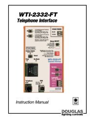
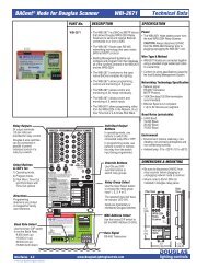
INSTALLATION<br />
Install programmable relay scanner inside relay panel.<br />
Connect all of relays to the relay scanner. If there are more<br />
than 24 relays, install additional scanners.<br />
Connect the master switches, timers or other devices to<br />
the relay scanner's inputs.<br />
After the relays of a panel have been assigned to lighting<br />
loads, determine which relays are to be switched together.<br />
Use the keypad built into the front of the programmable<br />
scanner to assign the relay groups for each of the 5 master<br />
switches possible. Directions are printed on the scanner for<br />
handy reference.<br />
In programming mode, the display LEDs of the scanner<br />
show which relays are included in a group. In normal<br />
mode, the LEDs show the state of the connected relay.<br />
FLICK WARN BEFORE OFF<br />
The flick warn feature is generally used with automatic timer<br />
controls. The timer signals the scanner to turn a relay group OFF.<br />
The scanner issues a flick warn so that the occupants have a 5<br />
minute opportunity to cancel the OFF signal.<br />
Occupants can cancel individual relays from being switched off by<br />
flicking them again with a local switch.<br />
Occupants can cancel the relay group from being switched off by<br />
pressing the master switch once. This will not switch the scanner,<br />
but will cancel the off signal for the group. Pressing the button<br />
again will switch the scanner.<br />
To select the "flick warn before OFF" function, use the keypad<br />
built into the scanner. Each relay group can have its own<br />
selection.<br />
Best results are obtained if occupants are aware of how to disable<br />
the OFF sweep after the flick warn. However, even if they are not<br />
aware, properly located switch stations will permit occupants to be<br />
able to turn the lights back ON.<br />
Douglas <strong>Relay</strong> Switches<br />
The master switch inputs of the<br />
programmable relay scanner are<br />
compatible with all models of<br />
Douglas relay switches.<br />
A maximum of 6 switches can be<br />
connected in parallel to the same<br />
switch input. The one-way<br />
measure of the wire length<br />
should not exceed 2000' (600m)<br />
if using 18 AWG wire.<br />
When connected to a<br />
programmable relay scanner, the<br />
LEDs of a Douglas led switch will<br />
show the state of a relay group.<br />
If any of the relays in the group<br />
are ON, the group is defined as<br />
being ON and the red on LED is<br />
lit. Only when all of the relays of<br />
a group are OFF is the group<br />
defined as being OFF and the<br />
green off LED is lit.<br />
Take care when using WR-8501<br />
LED switches. The WR-8501<br />
push button switch will always<br />
send a signal that is opposite to its<br />
current state. If repeat OFF or ON<br />
control is desired, use the WR-<br />
8001 rocker switch which is able<br />
to select an ON or OFF signal.<br />
Douglas Timer<br />
Automation<br />
The master switch inputs of the<br />
programmable scanner are<br />
compatible with Douglas timers<br />
that have relay switching outputs<br />
(eg: WTP-4408).<br />
1<br />
2<br />
3<br />
4<br />
5<br />
6<br />
7<br />
8<br />
9<br />
10<br />
11<br />
12<br />
1<br />
5<br />
7<br />
9<br />
11<br />
2<br />
4<br />
6<br />
8<br />
10<br />
12<br />
14<br />
16<br />
18<br />
20<br />
22<br />
24<br />
<strong>WRS</strong>-<strong>2224</strong><br />
<strong>Relay</strong><br />
<strong>Scanner</strong><br />
13<br />
15<br />
17<br />
19<br />
21<br />
23<br />
Sw<br />
Inputs<br />
13<br />
14<br />
15<br />
16<br />
17<br />
18<br />
19<br />
20<br />
21<br />
22<br />
23<br />
24<br />
W B<br />
WR-8001<br />
Rocker Switch<br />
WR-8501<br />
Pushbutton<br />
Switch with<br />
on & off LEDs<br />
Maximum:<br />
6 switches<br />
1<br />
2<br />
3<br />
B 45<br />
B<br />
Red<br />
Red<br />
Red<br />
WTP-4408<br />
Time Clock<br />
A B C D<br />
1 2 3<br />
1<br />
4<br />
2<br />
5<br />
3<br />
6<br />
Esc<br />
Clr<br />
47 85 96<br />
7 0 8 9<br />
0<br />
5 A I H<br />
9<br />
<br />
!<br />
"#$%&<br />
5 A I H<br />
9<br />
*<br />
B<br />
W<br />
Tr<br />
1<br />
2<br />
3<br />
4<br />
5<br />
6<br />
7<br />
8<br />
9<br />
10<br />
11<br />
12<br />
Momentary<br />
ON Contact<br />
OFF Contact<br />
Master Sw Override<br />
Maintained<br />
Form C<br />
Contact<br />
Set<br />
ON<br />
Diode<br />
OFF<br />
Diode<br />
Red<br />
Douglas switch OK<br />
with momentary<br />
contacts. NOT OK with<br />
maintained contacts<br />
Coil<br />
1<br />
3<br />
5<br />
7<br />
9<br />
11<br />
NO<br />
2<br />
4<br />
6<br />
8<br />
10<br />
12<br />
14<br />
16<br />
18<br />
20<br />
22<br />
24<br />
<strong>WRS</strong>-<strong>2224</strong><br />
<strong>Relay</strong><br />
<strong>Scanner</strong><br />
NC<br />
COM<br />
13<br />
15<br />
17<br />
19<br />
21<br />
23<br />
Sw<br />
Inputs<br />
13<br />
14<br />
15<br />
16<br />
17<br />
18<br />
19<br />
20<br />
21<br />
22<br />
23<br />
24<br />
W B<br />
1<br />
2<br />
3<br />
B 45<br />
B<br />
ON<br />
Diode<br />
OFF<br />
Diode<br />
B<br />
W<br />
Tr<br />
Interfaces 2.4<br />
C-2-1,2,3,4 -Controls, Pgm <strong>Scanner</strong><br />
www.DouglasLightingControls.com