3 NTIM and OBM
1. Overview 2. Programming Sequence. 3. NTIM and OBM - Marvell
1. Overview 2. Programming Sequence. 3. NTIM and OBM - Marvell

You also want an ePaper? Increase the reach of your titles
YUMPU automatically turns print PDFs into web optimized ePapers that Google loves.
ARMADA 16X Memory Controller Configuration <strong>and</strong> Tuning<br />
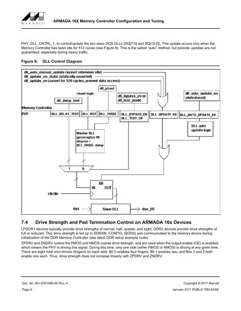
PHY_DLL_CNTRL_1, to control/update the two slave DQS DLLs (DQ[7:0] <strong>and</strong> DQ[15:0]). This update occurs only when the<br />
Memory Controller has been idle for 512 cycles (see Figure 8). This is the safest “auto” method, but periodic updates are not<br />
guaranteed, especially during heavy traffic.<br />
Figure 8:<br />
DLL Control Diagram<br />
7.4 Drive Strength <strong>and</strong> Pad Termination Control on ARMADA 16x Devices<br />
LPDDR1 devices typically provide drive strengths of normal, half, quarter, <strong>and</strong> eight. DDR2 devices provide drive strengths of<br />
full or reduced. This drive strength is set up in SDRAM_CONFIG_0[ODS] <strong>and</strong> communicated to the memory device during<br />
initialization of the DDR Memory Controller (see latest DDR setup example code).<br />
ZPDRV <strong>and</strong> ZNDRV control the PMOS <strong>and</strong> NMOS coarse drive strength, <strong>and</strong> are used when the output enable (OE) is enabled,<br />
which means the PHY is driving this signal. During this time, only one side (either PMOS or NMOS) is driving at any given time.<br />
There are eight total mini-drivers (fingers) on each side. Bit 0 enables four fingers, Bit 1 enables two, <strong>and</strong> Bits 3 <strong>and</strong> 2 both<br />
enable one each. Thus, drive strength does not increase linearly with ZPDRV <strong>and</strong> ZNDRV.<br />
Doc. No. MV-S301989-00 Rev. A Copyright © 2011 Marvell<br />
Page 8 January 2011 PUBLIC RELEASE