

Hams in Space!
Hams in Space! - Free and Open Source Software
Hams in Space! - Free and Open Source Software
- No tags were found...

You also want an ePaper? Increase the reach of your titles
YUMPU automatically turns print PDFs into web optimized ePapers that Google loves.
IC-475H. Most stations runn<strong>in</strong>g about 25 watts<br />
and up on AO-13's 70cm upl<strong>in</strong>k (for Mode B)<br />
were S-5 and above on the IC-970H 's 2m<br />
downl<strong>in</strong>k receiver. Similarly, stations us<strong>in</strong>g<br />
2m on the upl<strong>in</strong>k (for Mode J) and runn<strong>in</strong>g<br />
about 25 watts or more, resulted <strong>in</strong> downl<strong>in</strong>k<br />
signals <strong>in</strong> the range of S-4 to S-5. Stations<br />
us<strong>in</strong>g near 75 watts and up were produc<strong>in</strong>g<br />
S-9+ signals. Please note that your signals<br />
may vary due to the ga<strong>in</strong> of your antennas and<br />
loss <strong>in</strong> your transmission l<strong>in</strong>e, and the current<br />
squ<strong>in</strong>t angle of the satellite's antennas. In<br />
general, though, the results were very much<br />
on a par with other satellite receiver systems<br />
that I have used <strong>in</strong> the past.<br />
For transmitt<strong>in</strong>g, the 30 and 35 watts produced<br />
by the IC-970's 70cm and 2m transmitters<br />
resulted <strong>in</strong> below average signal levels<br />
when compared to many of the other downl<strong>in</strong>k<br />
signals on the satellite. To <strong>in</strong>crease my signal,<br />
I decided to activate the speech compressor.<br />
The speech compressor produced a very noticeable<br />
<strong>in</strong>crease <strong>in</strong> signal strength and improved<br />
the basic sound quality. I estimate the ga<strong>in</strong><br />
<strong>in</strong>crease was almost 6 dB (one ICOM S-unit).<br />
particular stored memory channel, is also<br />
available with the two rema<strong>in</strong><strong>in</strong>g positions of<br />
the SATELLITE switch.<br />
Scann<strong>in</strong>g<br />
The ma<strong>in</strong> and sub scann<strong>in</strong>g features are not<br />
necessarily needed for satellite operations,<br />
but they are good for local activity. The feature<br />
I liked best is that both the ma<strong>in</strong> and sub bands<br />
can be selected for scann<strong>in</strong>g at the same time<br />
(by us<strong>in</strong>g the Ma<strong>in</strong> and Sub Scan Switches] <strong>in</strong><br />
addition to the more common <strong>in</strong>dividual band<br />
scan feature found on most receivers.<br />
Both the ma<strong>in</strong> and subbands can have 99<br />
memory channels programmed, and they<br />
each have the capability to have a selected<br />
portion of their bandwidth scanned (this feature<br />
uses the P1 and P2 memory Channels).<br />
The IC-970H can perform four types of scann<strong>in</strong>g:<br />
programmed scan, which scans between<br />
two programmed scan edges; memory<br />
scan, which repeatedly scans all memory<br />
channels <strong>in</strong> the selected band; mode-select<br />
memory scan, which repeatedly scans memory<br />
channels with the same selected operat<strong>in</strong>g<br />
mode <strong>in</strong> a particular band; and multiband<br />
memory scan, which allows scann<strong>in</strong>g with an<br />
optional <strong>in</strong>stalled band.<br />
Satellite Packet Operation<br />
In addition to us<strong>in</strong>g the IC-970H for voice<br />
communications, 1 used the radio to copy<br />
telemetry from FQ-20, DOVE, and Pacsal.<br />
Currently, I am us<strong>in</strong>g a PAC-eOMM T<strong>in</strong>y-2<br />
and PSK-1 to decode the SPSK and AFSK<br />
telemetry signals from these birds with my<br />
IC-275H and IC-475H radios. To copy the<br />
telemetry us<strong>in</strong>g the IC-970H, I just <strong>in</strong>serted a<br />
microphone connector and connected the audio<br />
<strong>in</strong>put and ground of the PSK-1 or T<strong>in</strong>y-2<br />
(depend<strong>in</strong>g upon which bird I was copy<strong>in</strong>g<br />
from) to the microphone connector. This provided<br />
the bare m<strong>in</strong>imum connections required<br />
to perform telemetry reception. For DOVE<br />
(AFSK FM), I just tuned to 145.825 and let the<br />
bird pass over. (Here, I did not need to tune for<br />
Doppler.)<br />
However, for the FO-20 and Pacsat satellites<br />
(BPSK SSB), I needed to manually tune<br />
for the correct Doppler-shifted signal. This<br />
1200 MHz Option<br />
The IC-970H comes with 2m and 70cm<br />
band units <strong>in</strong>stalled trom the factory . These<br />
two bands are primarily used for Mode Band J<br />
satellite communications. In case you want to<br />
operate on Mode l (1296 MHz upl<strong>in</strong>k and<br />
70cm downl<strong>in</strong>k), the IC-970H lets you <strong>in</strong>stall<br />
the UX-97 1200 MHz optional band unit for<br />
Mode l use. The UX-97 supports SSB, plus<br />
CW and FM, and has 10 watts output power.<br />
Satellite Track<strong>in</strong>g and Memories<br />
In addition to allow<strong>in</strong>g you to store 99 different<br />
frequencies <strong>in</strong>to the per band memory<br />
channels, the IC-970H allows you to store 10<br />
upl<strong>in</strong>k/downl<strong>in</strong>k frequencies and mode pairs<br />
(transponder upl<strong>in</strong>k and downl<strong>in</strong>k track<strong>in</strong>g frequencies).<br />
I found this feature to be very convenient.<br />
I programmed frequencies for AO<br />
13's Mode B <strong>in</strong>to cnenner t. AO-13's Mode J<br />
<strong>in</strong>to channel 2, and FQ-20's Mode J frequencies<br />
<strong>in</strong>to channel 3. (To program <strong>in</strong>to a particular<br />
channel, the SAT£LLITE switch must be <strong>in</strong><br />
the SATL position.) Now when I need to use a<br />
particular mode on one of these satellites, I<br />
put the SATELLITE switch to the SATL position,<br />
enabl<strong>in</strong>g the 10 special memory channels;<br />
then I select a particular channel with the<br />
Memory Channel Switch, and turn the Satellite<br />
Switch to the correspond<strong>in</strong>g track<strong>in</strong>g direction<br />
(either N or A position). Tun<strong>in</strong>g with the<br />
ma<strong>in</strong> dial now changes the ma<strong>in</strong> and sub frequencies<br />
<strong>in</strong> either the same direction or <strong>in</strong>verse<br />
direction, accord<strong>in</strong>gly.<br />
How did I compensate for the Doppler shift?<br />
When operat<strong>in</strong>g <strong>in</strong> this manner and encounter<strong>in</strong>g<br />
Doppler shift, just deactivate the MAINI<br />
SUB switch, allow<strong>in</strong>g frequency changes on<br />
both the ma<strong>in</strong> and sub VFOs at the same time.<br />
Change the AX frequency just enough to allow<br />
for the Doppler shift. After this tun<strong>in</strong>g, activat<strong>in</strong>g<br />
the MAIN/SUB switch allows you to cont<strong>in</strong>ue<br />
to change frequencies on both the ma<strong>in</strong> and<br />
sub VFOs at the same time by us<strong>in</strong>g the ma<strong>in</strong><br />
dial.<br />
Track<strong>in</strong>g <strong>in</strong> this manner, but not us<strong>in</strong>g a<br />
38 73AmateurRadio Today. March,1991<br />
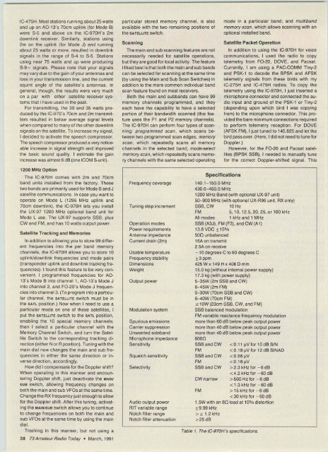
Frequency coverage<br />
Tun<strong>in</strong>g step <strong>in</strong>crement<br />
Operation modes<br />
Power requirements<br />
Antenna impedance<br />
Current dra<strong>in</strong> (2m)<br />
Usable temperature<br />
Frequency stability<br />
Dimensions<br />
Weight<br />
Output power<br />
Modulation system<br />
Spurious emissions<br />
Carrier suppression<br />
Unwanted sideband<br />
Microphone impedance<br />
Sensitivity<br />
Squelch sensitivity<br />
Selectivity<br />
Audio output power<br />
AIT variable range<br />
Notch filter range<br />
Notch filter attenuation<br />
Specifications<br />
140.1-150.0MHz<br />
430.0-450.0 MHz<br />
1200 MHz Band (with optional UX·97 unit)<br />
50-900 MHz (with optional UX-A96 unit, AX only)<br />
SSB, CW 10 Hz<br />
FM<br />
5,10,12.5,20, 25,0r1oo kHz<br />
All modes 1 kHz and 1 MHz<br />
SSB (A3J), FM (F3), and CW (A1)<br />
13.8 VDC ±15%<br />
500 unbalanced<br />
16A on transmit<br />
2.5A on receive<br />
- 10 degrees C to 60 degrees C<br />
± 3 ppm<br />
425Wx149Hx406Dmm<br />
15.0 kg (without <strong>in</strong>ternal power supply)<br />
17.3 kg (with power supply)<br />
5-35W (2m SSB and CW)<br />
6-45W (2m FM)<br />
5-30W (70cm SSB and CW)<br />
6-40W (70cm FM)<br />
s iow (23cm SSB, CW, and FM)<br />
SSB balanced modulation<br />
FM variable reactance frequency modulation<br />
more than 60 dB below peak output power<br />
more than 40 dB below peak output power<br />
more than 40 dB below peak output power<br />
6000<br />
SSB and CW<br />
FM<br />
SSB and CW<br />
FM<br />
SSB and CW<br />
CW narrow<br />
FM<br />
25dB<br />
Table 1. The IC-970H's specifica trons.


