thoroughly
Hobby World Corporation gasser conversion - Centuryhelimedia.com
Hobby World Corporation gasser conversion - Centuryhelimedia.com
- No tags were found...

Create successful ePaper yourself
Turn your PDF publications into a flip-book with our unique Google optimized e-Paper software.
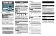
INTRODUCTION<br />
T700 GASSER CONVERSION<br />
Thank You<br />
Congratulations on the purchase of the newest product that enables the conversion of to gasoline power. This conversion kit was<br />
designed around the nitro version of the TREX 700 2011 model. There may be variances with earlier or future models so please <strong>thoroughly</strong><br />
go through the instructions to ensure you have all the parts necessary to complete the conversion. This conversion kit will allow<br />
efficient and inexpensive flights with your helicopter using gasoline for fuel.<br />
Warning<br />
This radio controlled model is not a toy! It is a precision machine requiring proper assembly and setup to avoid accidents. It is the<br />
responsibility of the owner to operate this product in a safe manner as it can inflict serious injury otherwise. It is recommended that if<br />
you are in doubt of your abilities, seek assistance from experienced radio control modelers and associations. Keep loose items that can<br />
get entangled in the rotor blades away for the main and tail blades, including loose clothing, hair, or other objects such as pencils and<br />
screwdrivers. Especially keep your hands away from the rotor blades. As manufacturer, we assume no liability for the use of this product.<br />
Flight Guidelines<br />
Please note this checklist is not intended to be a replacement for the content included in this instruction manual. Although it can<br />
be used as a quick start guide, we strongly suggest reading through this manual completely before proceeding.<br />
Always turn the transmitter on first<br />
Allow the gyro, and receiver to arm and initialize properly<br />
Do a pre-flight check making sure all electronics are working and look for any mechanical issues<br />
Fly the model<br />
Land the model<br />
Turn off the engine<br />
Always turn the transmitter off last<br />
General Guidelines<br />
Apply thread lock to all metal to metal thread contact points. Do not apply CA (cyanoacrylate) glue or thread lock to ny-lock nuts (metal nuts<br />
with plastic inserts). Diagrams indicated by bounding boxes for screws, bearings, etc. are illustrated at a 1-to-1 ratio. All other illustrations<br />
are not drawn to scale. Throughout this manual, you will find building tips. Please follow the tips and use common sense when building.<br />
Pre-assembly Information<br />
Upon opening the kit, all the major component parts are bagged for ease of assembly which correspond to the sections of the manual.<br />
Various assemblies have been pre-assembled however, only as a reference assembly. Final assembly is up to the user. Installation onto<br />
the particular parts, screws and nuts required for each step are packaged in the same bag as the parts. Be careful when opening each<br />
bag as not to lose any hardware. Care has been taken in filling and packing of each bag however mistakes do happen. If there is a parts<br />
shortage or missing hardware please contact us at:<br />
For support, please contact your local dealer/distributor<br />
Page 2
1.000<br />
REQUIRED ITEMS<br />
T700 GASSER CONVERSION<br />
6 CHANNEL<br />
CCPM TRANSMITTER<br />
(MINIMUM)<br />
SERVOS X 5<br />
6 CHANNEL RECEIVER<br />
(MINIMUM)<br />
CN2031<br />
4-WAY WRENCH<br />
CN2034A<br />
BALL LINK PLIERS<br />
CN2050<br />
PADDLE GAUGE<br />
DREMEL TOOL<br />
OR SIMILAR<br />
RECEIVER BATTERY<br />
HOBBY SCISSORS<br />
CN2017<br />
HEX DRIVERS<br />
1.5, 2.0, 2.5, 3.0, 4.0, 5.0<br />
1.000<br />
87 TO 92 OCTANE<br />
GASOLINE<br />
GYRO<br />
CN2027<br />
G-FORCE PITCH GAUGE<br />
CN3071<br />
TORPEDO GASSER<br />
TUNED MUFFLER<br />
23-30cc ZENOAH<br />
GASOLINE ENGINE<br />
NEEDLE NOSE<br />
PLIERS<br />
SLOW &<br />
Medium CA<br />
GLUE<br />
Medium<br />
(Medium)<br />
THREAD-<br />
LOCK<br />
METRIC RULER OR<br />
SIMILAR MEASURING<br />
DEVICE<br />
CN2255<br />
CONTROL ROD<br />
SETUP GAUGE<br />
690-720mm<br />
MAIN ROTOR BLADES<br />
SYNTHETIC<br />
OIL/GREASE<br />
2-STROKE<br />
MOTOR OIL<br />
ZIP TIES<br />
CN2051<br />
ACCURATECH BLADE BAL-<br />
ANCER V.2<br />
HOBBY KNIFE<br />
Warranty Period<br />
Hobby World Corporation warranties that the Products purchased (the “Product”) will be free from defects in materials and workmanship<br />
30 days from the date of purchase by the Purchaser.<br />
Limited Warranty<br />
(a) This warranty is limited to the original customer (“Purchaser”) and is not transferable. REPAIR OR REPLACEMENT AS PROVIDED<br />
UNDER WARRANTY IS THE EXCLUSIVE REMEDY OF THE PURCHASER. This warranty covers only those Products purchased from an<br />
authorized Hobby World Corporation dealer. Third party transactions are not covered by this warranty. Proof of purchase is required<br />
for the warranty claims. Further, Hobby World Corporation reserves the right to change or modify this warranty without notice and<br />
disclaims all other warranties, express or implied.<br />
(b) Limitations – HOBBY WORLD CORPORATION MAKES NO WARRANTY OR REPRESENTATION, EXPRESS OR IMPLIED, ABOUT NON-<br />
INFRINGEMENT, MERCHANTABILITY, OR FITNESS FOR A PARTICULAR PURPOSE OF THE PRODUCT. THE PURCHASER ACKNOLEDGES<br />
THAT THEY ALONE HAVE DETERMINED THAT THE PRODUCT WILL SUITABLY MEET THE REQUIREMENTS OF THE PURCHASER’S<br />
INTENDED USE.<br />
(c) Purchaser Remedy – Hobby World Corporation’s sole obligation hereunder shall be that Hobby World Corporation will, at its option,<br />
(i) repair or (ii) replace, any Products determined by Hobby World Corporation to be defective. In the event of a defect, these are the<br />
Purchaser’s exclusive remedies. Hobby World Corporation reserves the right to inspect any and all equipment involved in a warranty<br />
claim. Repair or replacement decisions are at the sole discretion of Hobby World Corporation. This warranty does not cover damage<br />
due to the improper installation, operation, maintenance, or attempted repair by anyone other than Hobby World Corporation. Return<br />
of any goods by Purchaser must be approved by Hobby World Corporation before shipment.<br />
Page 3
AMA RULES & REGULATIONS<br />
General<br />
T700 GASSER CONVERSION<br />
1) I will not fly my model aircraft in sanctioned events, air shows or model flying demonstrations until it has been proven to be airworthy<br />
by having been previously, successfully flight tested.<br />
2) I will not fly my model higher than approximately 400 feet within 3 miles of an airport without notifying the airport operator. I will<br />
give right-of-way and avoid flying in the proximity of full-scale aircraft. Where necessary, an observer shall be utilized to supervise flying<br />
to avoid having models fly in the proximity of full-scale aircraft.<br />
3) Where established, I will abide by the safety rules for the flying site I use, and I will not willfully or deliberately fly my models in a<br />
careless, reckless and/or dangerous manner.<br />
4) The maximum takeoff weight of a model is 55 pounds, except models flown under Experimental Aircraft rules.<br />
5) I will not fly my model unless it is identified with my name and address or AMA number on or in the model. (This does not apply to<br />
models while being flown indoors.)<br />
6) I will not operate models with metal-bladed propellers or with gaseous boosts, in which gases other than air enter their internal<br />
combustion engine(s); nor will I operate models with extremely hazardous fuels such as those containing tetranitromethane or hydrazine.<br />
Radio Control<br />
1) I will have completed a successful radio equipment ground range check before the first flight of a new or repaired model.<br />
2) I will not fly my model aircraft in the presence of spectators until I become a qualified flier, unless assisted by an experienced helper.<br />
3) At all flying sites a straight or curved line(s) must be established in front of which all flying takes place with the other side for<br />
spectators. Only personnel involved with flying the aircraft are allowed at or in front of the flight line. Intentional flying behind the flight<br />
line is prohibited.<br />
4) I will operate my model using only radio control frequencies currently allowed by the Federal Communications Commission. (Only<br />
properly licensed Amateurs are authorized to operate equipment on Amateur Band frequencies.)<br />
5) Flying sites separated by three miles or more are considered safe from site-to site interference, even when both sites use the<br />
same frequencies. Any circumstances under three miles separation require a frequency management arrangement, which may be<br />
either an allocation of specific frequencies for each site or testing to determine that freedom from interference exists. Allocation<br />
plans or interference test reports shall be signed by the parties involved and provided to AMA Headquarters. Documents of agreement<br />
and reports may exist between<br />
(1) Two or more AMA Chartered Clubs, (2) AMA clubs and individual AMA members not associated with AMA Clubs, or (3) two or<br />
more individual AMA members.<br />
6) For Combat, distance between combat engagement line and spectator line will be 500 feet per cubic inch of engine displacement.<br />
(Example: .40 engine = 200 feet.); electric motors will be based on equivalent combustion engine size. Additional safety requirements<br />
will be per the RC Combat section of the current Competition Regulations.<br />
7) At air shows or model flying demonstrations, a single straight line must be established, one side of which is for flying, with the<br />
other side for spectators.<br />
8) With the exception of events flown under AMA Competition rules, after launch, except for pilots or helpers being used, no powered<br />
model may be flown closer than 25 feet to any person.<br />
9) Under no circumstances may a pilot or other person touch a powered model in flight.<br />
Page 4
CLUTCH ASSEMBLY<br />
T700 GASSER CONVERSION<br />
Do not open all the bags prior to starting assembly. Open the bags step by step as you go through the instruction manual. The<br />
components are bagged to make assembly easier. The part numbers with an astericks* indicate they are OEM Align part numbers.<br />
If you do not have these or similar parts, this conversion kit will not work.<br />
1<br />
3<br />
4<br />
2<br />
5<br />
6<br />
7<br />
CA<br />
Clean the top of the pinion gear<br />
and the inside surfaces of both<br />
the upper and lower bearings<br />
inside the clutch shaft bearing<br />
block using alcohol. Apply a small<br />
amount of Red threadlock to<br />
the top edge of the clutch gear<br />
where it will contact the bearing.<br />
Press the bearing block in place,<br />
firmly seating the bearing against<br />
the top of the pinion gear.<br />
8<br />
9<br />
10<br />
This conversion kit uses the regular starting shaft and hex coupler to<br />
align the clutch to the clutchbell. Clean both the starting shaft and the<br />
inside race of the bearing inside the clutchbell and the inside race of<br />
the top starting shaft bearing. Apply a small amount of red threadlock<br />
positioned just above where the bottom clutchbell bearing will sit<br />
on the starting shaft. Slide the starting shaft up through the bearing<br />
blocks. Apply a small amount of medium threadlock to the top of the<br />
starting shaft and slide the hex coupler in place aligning the flat spot<br />
with one of the holes. Apply medium threadlock to the two M4x4 set<br />
screws and tighten in place.<br />
11<br />
CNM4x4SS<br />
12<br />
CNM3x8CS<br />
M3 CNM3LOCK<br />
CNBB511<br />
CNBB513<br />
CNBB1019<br />
13<br />
No. Part #<br />
Description Qty<br />
1<br />
2<br />
3<br />
4<br />
5<br />
6<br />
7<br />
8<br />
9<br />
10<br />
11<br />
12<br />
13<br />
Page 5<br />
HW6002 Hex Starter Adapter( 六 角 启 动 头 )<br />
1<br />
CNM4X4SS M4x4 Set Screw( 无 头 内 六 角 螺 丝 ) 2<br />
CNBB513 5X13X4 Bearing( 轴 承 ) 1<br />
HN7083* L=60.5mm Hex Mounting Bolt( 六 角 铝 柱 ) 2<br />
HN7083* Clutch Bearing Block( 离 合 器 轴 承 座 ) 2<br />
CNM3LOCK M3 Locknut(M3 防 松 螺 母 )<br />
2<br />
CNM3X8CS M3X8 Cap Screw( 杯 头 螺 丝 )<br />
2<br />
HN6007* Clutch Nut( 离 合 器 齿 轮 螺 母 ) 1<br />
CNBB1019 10X19X5 Bearing( 轴 承 )<br />
1<br />
HW6043B7 16T Clutch Gear(16 齿 离 合 器 齿 轮 ) 1<br />
HW6013G3 Clutch Bell Assembly 67mm( 离 合 器 罩 ) 1<br />
CNBB511 5X11X4 Bearing( 轴 承 )<br />
1<br />
HW6006T7 Start Shaft( 启 动 轴 )<br />
1
BEARING BLOCKS & ELEVATOR ARM<br />
T700 GASSER CONVERSION<br />
File or Shave<br />
TOP DOWN VIEW<br />
1<br />
10mm<br />
Elevator Lever<br />
2<br />
3<br />
1mm<br />
Main Shaft<br />
4<br />
5<br />
6 7<br />
8<br />
Use a file or a dremel tool to shave the elevator<br />
arm as indicated. Remove about 1mm depth and<br />
10mm wide of material from the arm.<br />
9<br />
11<br />
10<br />
CNBB1224<br />
CNM3x6BHCS<br />
Ø5X8.5<br />
CNM4x4SS<br />
No. Part #<br />
Description Qty<br />
1<br />
2<br />
3<br />
4<br />
5<br />
6<br />
7<br />
8<br />
9<br />
10<br />
11<br />
HN7033* Elevator Ball Link( 升 降 臂 连 杆 头 )<br />
1<br />
HN7033* Elevator Arm( 升 降 控 制 臂 )<br />
1<br />
CNM2.5X8CS M2.5X8 Cap Screw( 杯 头 螺 丝 )<br />
1<br />
CNM3X6BHCS M3X6 Button Head Screw( 圆 头 螺 丝 )<br />
2<br />
CNBB0730F 3X7X3 Bearing( 带 边 轴 承 )<br />
2<br />
CNM4X4SS M4x4 Set Screw( 无 头 内 六 角 螺 丝 )<br />
1<br />
HN7033* Elevator Lever( 升 降 连 动 控 制 臂 )<br />
1<br />
HN7033* Linkage Ball C(M3x3.5)( 球 头 C(M3X3.5))5X8.5 2<br />
HN7023A* Control Shaft( 连 动 秆 )<br />
1<br />
CNBB1224 12X24X6 Bearing( 轴 承 ) 2<br />
HN7031* Metal Bearing Block( 金 属 主 轴 固 定 座 )<br />
2<br />
CNBB37F<br />
CNM2.5x8CS<br />
Page 6
FUEL TANK ASSEMBLY<br />
T700 GASSER CONVERSION<br />
9<br />
Pay close attention when assembling the fuel tank.<br />
The vent tube must be bent and facing upwards when<br />
installed into the rubber stopper. There are 3 holes<br />
on the rubber stopper but notice only 2 are through<br />
holes. Cut the fuel line and attach the clunk to the<br />
line. Then attach the fuel line to the short brass tube.<br />
When cutting the fuel line, make sure you have enough<br />
slack in the fuel line so the clunk can reach all corners<br />
of the fuel tank. After installing the shorter brass tube<br />
with the fuel line, install the vent tube. Make sure the<br />
vent tube is positioned to point upwards in the fuel<br />
tank. Once you have everything positioned, slowly turn<br />
the M3.5x24 Phillips screw so that you barely grab<br />
the end of the small cap (#4). Once you insert the<br />
fuel tubing assembly into the tank, it will be very difficult<br />
to get this small cap out if you happen to drop<br />
it within the fuel tank. Making sure you still have the<br />
small cap (#4) attached to the fuel tubing assembly,<br />
push the fuel tubing assembly into the tank and start<br />
tightening the Phillips screw. This will pull the small<br />
cap (#4) closer to the large cap (#2) and expand the<br />
rubber stopper. Once tightened, gently tug on the assembly<br />
to make sure it is properly installed. It should<br />
not come out of the fuel tank.<br />
Bend one of the longer<br />
brass tubes into this<br />
shape. This will be the<br />
vent tube.<br />
1<br />
2<br />
3<br />
4<br />
5<br />
6<br />
7<br />
8<br />
CNM3.5x24ST<br />
No. Part #<br />
Description Qty<br />
1<br />
2<br />
HI3138B<br />
HI3138B<br />
Tapping Screw( 十 字 紧 固 螺 丝 )M3.5x24<br />
Large Cap( 油 箱 盖 )<br />
1<br />
1<br />
3 HI3138B Rubber Stopper( 油 箱 塞 )<br />
1<br />
4 HI3138B Small Cap( 油 箱 塞 固 定 座 )<br />
1<br />
5 HI3138B Long Tube-straight( 长 直 铜 油 管 )<br />
1<br />
6 HI3138B Pickup Tube-straight( 短 直 铜 油 管 )<br />
1<br />
7 HI3138B Plastic Tubing( 塑 胶 油 管 )<br />
1<br />
8 HI3138B Fuel Tank Set( 吸 油 嘴 )<br />
1<br />
9 HI6139 Fuel Tank( 油 箱 )<br />
1<br />
Page 7
SIDE FRAMES ASSEMBLY<br />
T700 GASSER CONVERSION<br />
10<br />
9<br />
7<br />
5<br />
15<br />
6<br />
8<br />
12 13<br />
11<br />
4<br />
3<br />
2<br />
1<br />
14<br />
球 头 Ø5X8.5<br />
CNBB0510<br />
M3X8 Collar Screw<br />
5x7.5x3<br />
CNBB0950<br />
3x5.5x0.3<br />
CNM3x6CS<br />
No. Part #<br />
Description Qty<br />
1<br />
2<br />
3<br />
4<br />
5<br />
6<br />
7<br />
8<br />
9<br />
10<br />
11<br />
12<br />
13<br />
14<br />
15<br />
CNM3LOCK M3 Locknut(M3 防 松 螺 母 )<br />
2<br />
HI6140T7 Fuel Tank Spacer( 油 箱 限 位 块 ) 2<br />
CNM3X8CS M3X8 Cup Screw( 杯 头 螺 丝 )<br />
2<br />
HI6119 Main Frames (R/L)( 左 右 主 体 侧 板 ) 2<br />
H6015B* M3X8 Button Head Collar Screw( 半 圆 头 轴 套 螺 丝 ) 8<br />
HI6116T7 Frame Bearing( 侧 板 轴 承 座 )<br />
2<br />
CNBB0510 5X10X4 Bearing( 轴 承 )<br />
2<br />
CNBB0950 5X9X3 Bearing( 轴 承 )<br />
4<br />
CNM3X5.5FW 3x5.5x0.3 Flat Washer( 平 面 垫 片 )<br />
2<br />
CNM3X6CS M3X6 Cap Screw( 杯 头 螺 丝 ) 2<br />
HN7034* Linkage Ball C(M3x3.5)( 球 头 C(M3X3.5))Ø5X8.5 6<br />
HN7034* Metal Aileron Lever( 金 属 左 右 控 制 摇 臂 )<br />
2<br />
H7023A* 5x7.5x3 Control Shaft Collar( 连 动 杆 套 圈 ) 2<br />
HI6139B Fuel Tank Isolators( 油 箱 垫 圈 )<br />
2<br />
OEM PART* 5x7x0.5 Washer<br />
2<br />
5x7x0.5<br />
Page 8
ELECTRONICS TRAYS<br />
T700 GASSER CONVERSION<br />
8<br />
2<br />
4 5<br />
6<br />
7<br />
1<br />
3<br />
12<br />
9<br />
10<br />
16<br />
14<br />
15<br />
11<br />
13<br />
CA<br />
Ø3xØ4.8x0.3<br />
Ø3xØ4.4x3<br />
CNBB0630<br />
CNM2.5x6FHCS<br />
球 头 Ø5X8.5<br />
CNM3x8BHCS<br />
CNM3x14CS<br />
CNM3x12BHCS<br />
Ø3xØ8x2<br />
No. Part #<br />
Description Qty<br />
1<br />
2<br />
3<br />
4<br />
5<br />
6<br />
7<br />
8<br />
9<br />
10<br />
11<br />
12<br />
13<br />
14<br />
15<br />
16<br />
HN7065* Linkage Ball C(M3x3.5)( 球 头 C(M3X3.5))Ø5X8.5 2<br />
CNM3X12BHCS M3X12 Button Head Screw( 圆 头 螺 丝 )<br />
1<br />
CNM3X4.8FW Ø3xØ4.8x0.3 Flat Washer( 平 面 垫 片 )<br />
2<br />
CNBB0630 3X6X2.5 Bearing( 轴 承 )<br />
2<br />
HN6038* Tail Control Arm( 尾 控 制 臂 )<br />
1<br />
HN6038* Ø3xØ4.4x3 Collar( 尾 控 制 臂 铝 套 ) 1<br />
HN6019*<br />
CNM2.5x6FHCS<br />
Frame Mounting Block( 机 身 固 定 块 )<br />
M2.5x6 Flush Head Cap Screws( 斜 头 内 六 角 螺 丝 )<br />
1<br />
4<br />
HW6113T7A<br />
HW6113T7<br />
CNM3X8BHCS<br />
Electronic Board( 电 子 板 )<br />
L=61mm Frame Support Bar( 带 平 面 铝 柱 )<br />
M3X8 Button Head Screw( 圆 头 螺 丝 )<br />
1<br />
2<br />
2<br />
HN7078*<br />
HN7078*<br />
L=61mm Frame Mounting Bolt( 机 身 铝 柱 )<br />
Ø3xØ5x7.3 Canopy Support( 机 头 罩 支 撑 柱 )<br />
2<br />
2<br />
CNM3X14CS M3X14 Cup Screw( 杯 头 螺 丝 )<br />
2<br />
HN7078* Canopy Spacer( 机 头 罩 支 撑 垫 圈 )<br />
2<br />
CN2218S Ø3xØ8x2 M3 Specialty Washer( M3 特 殊 垫 片 ) 2<br />
Page 9
ENGINE ASSEMBLY<br />
1<br />
T700 GASSER CONVERSION<br />
2<br />
6.5x13x18<br />
x13x0.5<br />
3<br />
CNM6x16CS<br />
6.5x13x1<br />
CNLR1018<br />
CNM2.5x8CS<br />
CNM3x4SS<br />
4<br />
5<br />
CNM4x10FHCS<br />
CNM3x6FHCS<br />
CNM2.5x16CS<br />
CNM3x8BHCS<br />
Build the fan by placing Medium threadlock into the threaded holes on the fan<br />
hub (#6). Attach the fan to the hub as shown and install the M3x6 flush head<br />
cap screws making sure the screws fall into the beveled hole on the fan.<br />
7<br />
18<br />
19<br />
17<br />
Notice the<br />
flat spots<br />
6<br />
9<br />
10<br />
8<br />
11<br />
12<br />
13<br />
14<br />
15<br />
No. Part #<br />
Description Qty<br />
1<br />
2<br />
3<br />
4<br />
5<br />
6<br />
7<br />
8<br />
9<br />
10<br />
11<br />
12<br />
13<br />
14<br />
15<br />
16<br />
17<br />
18<br />
19<br />
20<br />
CNBB1014A<br />
HW6011G3<br />
HI6020B<br />
Clutch One Way Bearing (10mm)( 单 向 轴 承 )<br />
Clutch Shoe 59mm ( 离 合 器 )<br />
Plastic Cooling Shroud( 风 扇 罩 )<br />
1<br />
1<br />
1<br />
CNM6x16CS Cap Screw( 杯 头 内 六 角 螺 丝 )M6x16<br />
1<br />
CNM6.5x13FW Washer( 垫 片 )6.5x13x1<br />
1<br />
HI6012<br />
CNM2.5x8CS<br />
Cooling Fan Hub ( 风 扇 座 )<br />
Cap Screw( 杯 头 内 六 角 螺 丝 )M2.5x8<br />
1<br />
1<br />
HI6011 Two Way Cooling Fan( 风 扇 ) 1<br />
CNM3x6FHCS Flush Head Cap Screws( 斜 头 内 六 角 螺 丝 )M3x6 5<br />
CNM5x10FHCS M5X10 Flush Head Cap Screws( 斜 头 内 六 角 螺 丝 ) 4<br />
CNLR1018 Ultra Short Steel Ball( 球 头 螺 丝 )<br />
1<br />
HW6192B Carburetor Arm( 化 油 器 控 制 臂 )<br />
1<br />
CNM3x4SS Set Screw( 无 头 内 六 角 螺 丝 )M3X4<br />
1<br />
Z231<br />
Engine( 引 擎 )<br />
1<br />
CNM2.5x8CS Cap Screw( 杯 头 内 六 角 螺 丝 )M2.5x8<br />
2<br />
CNM2.5x16CS Cap Screw( 杯 头 内 六 角 螺 丝 )M2.5x16<br />
1<br />
HW6116T7 L=61mm Cooling Shroud Plate Support Bar ( 铝 柱 ) 1<br />
HW6118H3 Cooling Shroud Mounting Plate( 挡 风 板 )<br />
1<br />
CNM3x8BHCS<br />
HW6182<br />
M3x8 Button Head Cap Screw( 圆 头 内 六 角 螺 丝 )<br />
8x13x0.5 Spacer<br />
2<br />
4<br />
When tightening the M6x16 bolt, you can use a piston locking<br />
tool made for gasoline engines or you can remove the spark plug<br />
and stuff nylon rope into the piston hole. This will allow you to<br />
torque the bolt without the engine spinning. NEVER grab the<br />
bottom of the crank shaft where the starter attaches and tighten<br />
the bolt holding fan/clutch hub.<br />
16<br />
20<br />
Once you tighten the M3X10 Flush Head Cap Screws (#10), the Cooling<br />
Shroud Mounting Plate (#18) should be snug and not move. If it can<br />
still shift or moves, then install the 8x13x0.5 spacers (#20). The reason<br />
for this is the chamfer depth found on some Zenoah engines are not<br />
consistent with others, therefore some engines will require the spacers<br />
and some will not.<br />
Page 10<br />
Venturi style intake does not<br />
come with the engine.
LANDING FRAME STRUCTURE<br />
T700 GASSER CONVERSION<br />
When installing the engine assembly to the frames, do not tighten one side<br />
all the way leaving the other side completely loose. Tighten the M4x20 bolts<br />
on either side of the frames evenly moving from one side to the other. Leave<br />
the engine bolts loose for now as you will need to adjust the engine position<br />
once you attach the side frames to this engine assembly.<br />
Make sure to apply medium threadlock to these bolts. After you have installed<br />
the left and right M4x20 bolts, install the front engine block making<br />
sure to use medium threadlock on the M4x20 bolt holding the engine’s head<br />
in place.<br />
CA<br />
1 2<br />
12<br />
13<br />
Install the landing skids onto the landing struts one side at a time.<br />
After installing the landing skids, position, the landing struts on the<br />
skids so that they match up with the mounting positions on the<br />
frames. Place the washers onto the M3x18 cap screws and then apply<br />
medium threadlock. Install the screws through the landing struts<br />
and tighten onto the frames. Turn the landing skids so that the curve<br />
towards the front is facing straight up. Install the four M3x4 set<br />
screws to lock the skids into place. Do not tighten these too much<br />
as you can crack the plastic struts. Lastly, install the landing skid<br />
stoppers.<br />
9<br />
4<br />
5<br />
3<br />
Hint: Leave the front strut’s set screws and the<br />
M3x18 cap screws off. This will allow you to<br />
slide the strut forward giving you access to tighten<br />
the front engine mounting block once you attach<br />
the engine assembly to the side frames.<br />
7<br />
6<br />
8<br />
10 11<br />
CNM3x7FW<br />
CNM2.5x8CS<br />
CNM4x20CS<br />
CNM4x10FW<br />
CNM3x4SS<br />
CNM3x18CS<br />
No. Part #<br />
Description Qty<br />
1<br />
2<br />
3<br />
4<br />
5<br />
6<br />
7<br />
8<br />
9<br />
10<br />
11<br />
12<br />
13<br />
HW6117G3A Front Engine Mounting Block ( 引 擎 固 定 块 ) 1<br />
CNM4x20CS M4X20 Cap Screw( 杯 头 内 六 角 螺 丝 )<br />
1<br />
HW6117G30 Landing Gear Frame( 引 擎 座 底 板 ) 1<br />
CNM3x7FW 3x7x1 Washer( 垫 片 )<br />
2<br />
CNM2.5x8CS M2.5x8 Cap Screw( 杯 头 内 六 角 螺 丝 )<br />
2<br />
HI6122D Landing Struts( 脚 架 ) 2<br />
CNM3x4SS M3x4 Set Screw( 无 头 内 六 角 螺 丝 )<br />
4<br />
HW3123B Aluminum Skids with Caps ( 脚 架 弯 管 )<br />
2<br />
CNM3x7FW 3X7X1 Washer( 垫 片 )<br />
4<br />
CNM3x18CS M3x18 Cap Screw( 杯 头 内 六 角 螺 丝 )<br />
4<br />
HW3123B Skid Caps( 脚 架 塞 )<br />
4<br />
CNM4x20CS M4X20 Cap Screw( 杯 头 内 六 角 螺 丝 )<br />
2<br />
CNM4x10FW 4X10X1 Washer( 垫 片 )<br />
4<br />
Page 11
FRAME REINFORCEMENTS<br />
T700 GASSER CONVERSION<br />
1<br />
2<br />
3<br />
4<br />
7<br />
5<br />
6<br />
Radiused edge goes<br />
into the radius on the<br />
frame<br />
11<br />
10<br />
9<br />
8<br />
After sliding the side frame assembly onto the engine frame assembly,<br />
now is the the time to apply medium threadlock to the<br />
M4x20 Cap Screws and tighten them down. Position the engine<br />
and spin the clutchbell by hand making sure it spins freely and<br />
doesn’t catch on the clutch shoe. If it does, you will need to position<br />
the engine within the bottom frame before tightening the<br />
screws. Do not forget to tighten the front screw on the engine<br />
head on top of the front struts.<br />
CNM3x14BHCS<br />
CNM3x10BHCS<br />
CNM3x16BHCS<br />
Ø3xØ5x4<br />
No. Part #<br />
Description Qty<br />
1<br />
2<br />
3<br />
4<br />
5<br />
6<br />
7<br />
8<br />
9<br />
10<br />
11<br />
HI6116TFS Front Reinforcement Plate(Left) ( 右 机 身 前 侧 板 补 板 强 ) 1<br />
HI6031T7 L=61mm Frame Mounting Bolt( 机 身 铝 柱 )<br />
1<br />
HI6116TFS<br />
CNM3X10BHCS<br />
Front Reinforcement Plate(Right) ( 左 机 身 前 侧 板 补 板 强 )<br />
M3X10 Button Head Screw( 圆 头 螺 丝 )<br />
1<br />
2<br />
CNM3X14BHCS M3X14 Button Head Screw( 圆 头 螺 丝 )<br />
4<br />
HW6117TSF<br />
CNM3X16BHCS<br />
Front Frame Spacer( 机 身 前 侧 板 垫 块 )<br />
M3X16 Button Head Screw( 圆 头 螺 丝 )<br />
2<br />
2<br />
HW6117TS 3x5x4 Aluminum Sleeve( 铝 套 )<br />
2<br />
HW6117TSR<br />
CNM3X14BHCS<br />
Rear Frame Spacer( 机 身 后 侧 板 垫 块 )<br />
M3X14 Button Head Screw( 圆 头 螺 丝 )<br />
2<br />
2<br />
HI6116TRS Boom Support Reinforcement Plate ( 机 身 后 侧 板 补 强 ) 2<br />
Page 12
RECEIVER & CANOPY MOUNT<br />
T700 GASSER CONVERSION<br />
CA<br />
1<br />
3<br />
2<br />
11<br />
4<br />
5 6<br />
7<br />
If you were required to<br />
use the spacers for the<br />
cooling shroud mounting<br />
plate on page 10,<br />
you will need to elongate<br />
these holes by<br />
1mm upwards.<br />
10<br />
9 8<br />
CNM3x8BHCS<br />
CNM2.5x8CS<br />
Ø3xØ5x3<br />
CNM3x15SS<br />
CNM3x10BHCS<br />
M3X8<br />
No. Part #<br />
Description Qty<br />
1<br />
2<br />
3<br />
4<br />
5<br />
6<br />
HN7050*<br />
HN7050*<br />
HN6015B*<br />
H70087*<br />
H70087*<br />
CNM2.5x8CS<br />
Receiver Mount ( 接 受 机 座 )<br />
L=60.5mm Hex Mounting Bolt( 六 角 铝 柱 )<br />
M3X8 Button Head Collar Screw( 半 圆 头 轴 套 螺 丝 )<br />
M3X15 Stud( 无 头 全 牙 螺 丝 )<br />
Canopy Standoff( 机 头 固 定 铝 柱 )<br />
M2.5x8 Cap Screw( 杯 头 内 六 角 螺 丝 )<br />
1<br />
4<br />
6<br />
2<br />
2<br />
2<br />
7 HI6118T7S Head Fixed Plate( 机 头 固 定 板 ) 1<br />
8 HI6118T L=61mm Aluminum Column( 带 平 面 铝 柱 )<br />
1<br />
9 HW6205 3X5X2 Spacer( 铁 套 )<br />
2<br />
10 CNM3X10BHCS M3X10 Button Head Screw( 圆 头 螺 丝 )<br />
2<br />
11 CNM3X8BHCS M3X8 Button Head Screw( 圆 头 螺 丝 )<br />
2<br />
Page 13
TAIL TRANSMISSION ASSEMBLY<br />
T700 GASSER CONVERSION<br />
1<br />
3<br />
10<br />
2<br />
4<br />
7<br />
5<br />
9<br />
8<br />
6<br />
CNBB1350<br />
M3 CNM3LOCK<br />
No. Part #<br />
Description Qty<br />
1<br />
2<br />
3<br />
4<br />
5<br />
6<br />
7<br />
8<br />
9<br />
10<br />
HN7046* Tail Boom Mount(Left) ( 左 尾 管 固 定 座 ) 1<br />
HN7046* L=60.5mm Hexagonal Bolt( 六 角 铝 柱 )<br />
6<br />
CNBB1350 5X13X4 Bearing (5x13x4 轴 承 )<br />
2<br />
HN7043* Front Drive Gear Assembly( 尾 传 动 导 输 出 轴 组 ) 1<br />
HN7043* Tail Boom Mount(Right) ( 右 尾 管 固 定 座 )<br />
1<br />
CNM3LOCK M3 Locknut(M3 防 松 螺 母 )<br />
4<br />
HN7043* Front Umbrella Gear( 前 轴 传 伞 齿 轮 )<br />
1<br />
CNBB1218 12X18X4 Bearing (12x18x4 轴 承 )<br />
2<br />
HN7047* Tail Boom ( 尾 管 )<br />
1<br />
CNM3x14CS M3x14 Cap Screw( 杯 头 内 六 角 螺 丝 )<br />
4<br />
CNM3x14CS<br />
Page 14
TAILBOOM & SUPPORTS<br />
T700 GASSER CONVERSION<br />
1<br />
5<br />
4<br />
2<br />
6<br />
3<br />
Ø4xØ6x4<br />
CNM4x20CS<br />
M3X8<br />
4x10x1<br />
No. Part #<br />
Description Qty<br />
1<br />
2<br />
3<br />
4<br />
5<br />
HN6015B*<br />
HN7055A*<br />
CNM4x20CS<br />
HN7055A*<br />
HN7048*<br />
M3X8 Button Head Collar Screw( 半 圆 头 轴 套 螺 丝 )<br />
Tail Boom Brace( 尾 管 支 撑 架 )<br />
M4x20 Cap Screw( 杯 头 内 六 角 螺 丝 )<br />
4x6x4 Aluminum Sleeve( 铝 套 )<br />
L=61mm Frame Mounting Bolt( 机 身 铝 柱 )<br />
4<br />
2<br />
2<br />
2<br />
1<br />
6 HN7055A* 4x10X1 Washer<br />
2<br />
Page 15
MAIN GEAR ASSEMBLY<br />
T700 GASSER CONVERSION<br />
1<br />
Drop some medium threadlock into the<br />
six holes on the main gear case. Then<br />
use the M3x8 button head cap screws<br />
and install through the main gear case.<br />
Make sure to use threadlock sparingly<br />
as to not get excess threadlock onto<br />
the plastic gear.<br />
2<br />
If in the future your one-way bearing or<br />
sleeve is worn or damaged, it is highly<br />
recommended to replace the sleeve and<br />
one-way bearing hub at the same time.<br />
3<br />
4<br />
CNM3x8BHCS<br />
CNM2.5x8CS<br />
CNBB1521<br />
5<br />
6<br />
7<br />
No. Part #<br />
Description Qty<br />
1<br />
2<br />
3<br />
4<br />
5<br />
6<br />
7<br />
8<br />
9<br />
10<br />
CNM3X8BHCS<br />
HI6057T7<br />
HN7002*<br />
HN7002<br />
CNBB1521<br />
HN7002*<br />
HN7002*<br />
HN7002*<br />
CNM2.5x8CS<br />
HN7020*<br />
M3X8 Button Head Screw( 圆 头 螺 丝 )<br />
103T Main Gear(103 齿 齿 轮 )<br />
Main Shaft Auto Sleeve( 主 齿 轮 铁 套 )<br />
One-Way Bearing Cover( 单 向 轴 承 上 盖 )<br />
15x21x4 Bearing ( 轴 承 )<br />
One-Way Bearing Collar( 单 向 轴 承 外 环 )<br />
One-Way Bearing ( 单 向 轴 承 )<br />
One-Way Bearing Mount( 单 向 轴 承 下 盖 )<br />
M2.5x8 Cap Screw( 杯 头 内 六 角 螺 丝 )<br />
150T Tail Drive Gear( 尾 驱 动 齿 轮 )<br />
6<br />
1<br />
1<br />
1<br />
2<br />
1<br />
1<br />
1<br />
6<br />
1<br />
8<br />
9<br />
10<br />
Page 16
MAIN SHAFT TO MAIN GEAR ASSEMBLY<br />
T700 GASSER CONVERSION<br />
5<br />
7<br />
6<br />
Use the main shaft spacers provided originally with the<br />
TREX 700 kit to shim the main shaft. Once the right<br />
thickness spacer is chosen, pull up on the head to ensure<br />
there is no play between the main shaft and the main<br />
gear hub.<br />
1 2<br />
3<br />
4<br />
CNM3x10BHCS<br />
CNM4LOCK<br />
12x16<br />
CNM4x27CS<br />
No. Part #<br />
Description Qty<br />
1<br />
2<br />
3<br />
4<br />
5<br />
6<br />
7<br />
HW6114T7 Frame Reinforcement (Right)( 左 金 属 机 身 补 强 板 ) 1<br />
CNM3X10BHCS M3X10 Button Head Screw( 圆 头 螺 丝 )<br />
6<br />
CNM4X27CS M4x27 Cap Screw( 杯 头 内 六 角 螺 丝 )<br />
1<br />
CNM4LOCK M4 Lock-nut(M4 螺 母 )<br />
1<br />
HW6114T7<br />
HN7010-1*<br />
Frame Reinforcement (Left)( 右 金 属 机 身 补 强 板 )<br />
Main Shaft( 主 轴 )<br />
1<br />
1<br />
HN7075* Main Shaft Spacer<br />
1<br />
Page 17
PUSHROD MEASUREMENTS<br />
T700 GASSER CONVERSION<br />
1<br />
2<br />
4<br />
3<br />
HEL PFUL TOOL<br />
5<br />
PART# CN2255: CONTROL ROD SETUP GAUGE<br />
33<br />
42<br />
66<br />
59<br />
72<br />
92<br />
75<br />
87<br />
108<br />
2<br />
3<br />
No. Part # Description Qty<br />
1 HN7058* Ball Link( 连 杆 头 )<br />
20<br />
2 HN7064* L=42mm Linkage Rod( 连 杆 ) 2<br />
3 HN7064* L=72mm Linkage Rod( 连 杆 ) 2<br />
4 HN7064* L=87mm Linkage Rod( 连 杆 ) 2<br />
5 HN7064* L=260mm Linkage Rod( 连 杆 ) 1<br />
5 HN7064* L=243mm Carbon Fiber Tube( 碳 纤 管 ) 1<br />
6 HN7064* L=90mm Linkage Rod( 连 杆 ) 1<br />
4<br />
7<br />
6<br />
76<br />
90<br />
6<br />
109<br />
243<br />
260<br />
280<br />
Page 19<br />
5
MUFFLER & ESSENTIALS<br />
T700 GASSER CONVERSION<br />
The muffler is not an included item. It is an optional item that<br />
offers better performance but the stock can muffler from the<br />
engine can be used.<br />
1<br />
2 3<br />
6<br />
5<br />
4<br />
8<br />
7<br />
10<br />
9<br />
CNM3x4SS<br />
CNM5x20CS<br />
No. Part #<br />
Description Qty<br />
1<br />
2<br />
3<br />
4<br />
5<br />
6<br />
7<br />
8<br />
9<br />
10<br />
NOT INCLUDED Gyro ( 陀 螺 仪 )<br />
1<br />
NOT INCLUDED<br />
NOT INCLUDED<br />
NOT INCLUDED<br />
Anti-vibration Pad ( 防 震 垫 )<br />
Battery( 电 池 )<br />
Ties( 束 带 )<br />
1<br />
1<br />
1<br />
CN3071 M5X20 Cap Screw( 杯 头 内 六 角 螺 丝 )<br />
2<br />
CN3071 M5X8 Lock Washer( 弹 簧 垫 片 )<br />
2<br />
CN3071 Speed Torpedo V2 Muffler( 排 气 管 )<br />
1<br />
CNM3x4SS M3x4 Set Screw( 无 头 内 六 角 螺 丝 )<br />
2<br />
NOT INCLUDED Receiver( 接 受 机 )<br />
1<br />
NOT INCLUDED Tubing( 油 管 ) 2<br />
Page 20
80<br />
MOUNTING CANOPY<br />
T700 GASSER CONVERSION<br />
3<br />
4<br />
5<br />
2<br />
1<br />
30<br />
In order to use the original canopy,<br />
you will need to trim as indicated.<br />
These measurements<br />
are in millimeters.<br />
Congratulations on finishing the build of the gasser conversion for your T700. Please follow your instruction manual on setting up<br />
your transmitter and gyro systems. Also it is very important that you follow the instructions included with the Zenoah engine for<br />
the break in process and finally tuning the engine. If the steps are not followed your engine will not perform at it’s optimum levels.<br />
3x8x1<br />
CNM3x12CS<br />
No. Part #<br />
Description Qty<br />
1 CNM3X12CS M3X12 Cap Screw( 圆 头 螺 丝 )<br />
2<br />
2 HN7077* Canopy Mount( 机 头 固 定 座 )<br />
2<br />
3<br />
4<br />
HC7002*<br />
HN7059*<br />
Canopy( 机 头 )<br />
Canopy Grommet ( 橡 皮 环 )<br />
1<br />
4<br />
5 OEM PART* 3X8X1 Washer<br />
2<br />
Page 21
PERSONAL BUILD NOTES<br />
T700 GASSER CONVERSION<br />
Page 22