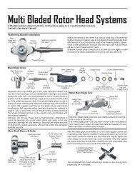
VERSION 2.0
VERSION 2.0 - Centuryhelimedia.com
VERSION 2.0 - Centuryhelimedia.com
- No tags were found...

You also want an ePaper? Increase the reach of your titles
YUMPU automatically turns print PDFs into web optimized ePapers that Google loves.
<strong>VERSION</strong> <strong>2.0</strong><br />
Kit Features:<br />
Lightweight yet extremely strong carbon fiber frames.<br />
High gloss large diameter 25mm tail boom with belt drive system.<br />
Blade grips accommodate blades 14mm to 16mm blade roots.<br />
300 mL fuel tank for long engine run time.<br />
Convenient and easy access to spark plug.<br />
Triple bearing supported blade grips and tail blade grips.<br />
Machined center dual ball bearing swashplate for 120 degree CCPM.<br />
Adjustable bell-hiller ratio allows tuning for preferred cyclic response.<br />
Tunable flight characteristics for stability or speed.<br />
Specifications:<br />
Length: 1397mm<br />
Height: 432mm<br />
Width: 260mm<br />
Main rotor diameter: 1580mm<br />
Tail rotor diameter: 282.5mm<br />
Main rotor blades: 690mm-720mm<br />
Tail rotor blades: 95mm<br />
© 2013 Century Helicopter Products - All rights reserved.<br />
Version 1.00
INTRODUCTION<br />
Radikal G30 v.2<br />
Thank You<br />
Congratulations on the purchase of the latest Century Gasser series, the Radikal G30. You’re about to build one of the world’s lightest<br />
fully functional 3D aerobatic helicopters powered by the Zenoah 23 to 30cc gasoline engine. Be sure to read through and follow the<br />
instructions during the build.<br />
Warning<br />
This radio controlled model is not a toy! It is a precision machine requiring proper assembly and setup to avoid accidents. It is the<br />
responsibility of the owner to operate this product in a safe manner as it can inflict serious injury otherwise. It is recommended that if<br />
you are in doubt of your abilities, seek assistance from experienced radio control modelers and associations. Keep loose items that can<br />
get entangled in the rotor blades away for the main and tail blades, including loose clothing, hair, or other objects such as pencils and<br />
screwdrivers. Especially keep your hands away from the rotor blades. As manufacturer, we assume no liability for the use of this product.<br />
Flight Guidelines<br />
Please note this checklist is not intended to be a replacement for the content included in this instruction manual. Although it can<br />
be used as a quick start guide, we strongly suggest reading through this manual completely before proceeding.<br />
Always turn the transmitter on first<br />
Allow the gyro, and receiver to arm and initialize properly<br />
Do a pre-flight check making sure all electronics are working and look for any mechanical issues<br />
Fly the model<br />
Land the model<br />
Turn off the engine<br />
Always turn the transmitter off last<br />
General Guidelines<br />
Apply thread lock to all metal to metal thread contact points. Do not apply CA (cyanoacrylate) glue or thread lock to ny-lock nuts (metal nuts<br />
with plastic inserts). Diagrams indicated by bounding boxes for screws, bearings, etc. are illustrated at a 1-to-1 ratio. All other illustrations<br />
are not drawn to scale. Throughout this manual, you will find building tips. Please follow the tips and use common sense when building.<br />
Pre-assembly Information<br />
Upon opening the kit, all the major component parts are bagged for ease of assembly which correspond to the sections of the manual.<br />
Various assemblies have been pre-assembled however, only as a reference assembly. Final assembly is up to the user. Installation onto<br />
the particular parts, screws and nuts required for each step are packaged in the same bag as the parts. Be careful when opening each<br />
bag as not to lose any hardware. Care has been taken in filling and packing of each bag however mistakes do happen. If there is a parts<br />
shortage or missing hardware please contact us at:<br />
Century Helicopter Products<br />
1740-C Junction Ave.<br />
San Jose, CA. 95112<br />
www.centuryheli.com<br />
Page 2
1.000<br />
REQUIRED ITEMS<br />
Radikal G30 v.2<br />
6 CHANNEL<br />
CCPM TRANSMITTER<br />
(MINIMUM)<br />
SERVOS X 5<br />
6 CHANNEL RECEIVER<br />
(MINIMUM)<br />
CN2031<br />
4-WAY WRENCH<br />
CN2034A<br />
BALL LINK PLIERS<br />
CN2050<br />
PADDLE GAUGE<br />
DREMEL TOOL<br />
OR SIMILAR<br />
RECEIVER BATTERY<br />
HOBBY SCISSORS<br />
CN2017<br />
HEX DRIVERS<br />
1.5, <strong>2.0</strong>, 2.5, 3.0, 4.0, 5.0<br />
1.000<br />
87 TO 92 OCTANE<br />
GASOLINE<br />
GYRO<br />
CN2027<br />
G-FORCE PITCH GAUGE<br />
CN3070<br />
20cc TORPEDO<br />
GASSER TUNED<br />
MUFFLER<br />
23CC-30CC ZENOAH<br />
GASOLINE ENGINE<br />
NEEDLE NOSE<br />
PLIERS<br />
ELECTRONIC<br />
IGNITION<br />
BATTERY<br />
SLOW &<br />
Medium CA<br />
GLUE<br />
Medium<br />
(Medium)<br />
THREAD-<br />
LOCK<br />
METRIC RULER OR<br />
SIMILAR MEASURING<br />
DEVICE<br />
CN2255<br />
CONTROL ROD<br />
SETUP GAUGE<br />
690MM TO 720MM<br />
MAIN ROTOR BLADES<br />
SYNTHETIC<br />
OIL/GREASE<br />
2-STROKE<br />
MOTOR OIL<br />
ZIP TIES<br />
CN2051<br />
ACCURATECH BLADE BAL-<br />
ANCER V.2<br />
HOBBY KNIFE<br />
Warranty Period<br />
Century Helicopter Products warranties that the Products purchased (the “Product”) will be free from defects in materials and workmanship<br />
30 days from the date of purchase by the Purchaser.<br />
Limited Warranty<br />
(a) This warranty is limited to the original customer (“Purchaser”) and is not transferable. REPAIR OR REPLACEMENT AS PROVIDED<br />
UNDER THIS WARRANTY IS THE EXCLUSIVE REMEDY OF THE PURCHASER. This warranty covers only those Products purchased<br />
from an authorized Century Helicopter Products dealer. Third party transactions are not covered by this warranty. Proof of purchase is<br />
required for warranty claims. Further, Century Helicopter Products reserves the right to change or modify this warranty without notice<br />
and disclaims all other warranties, express or implied.<br />
(b) Limitations- CENTURY HELICOPTER PRODUCT MAKES NO WARRANTY OR REPRESENTATION, EXPRESS OR IMPLIED, ABOUT NON-<br />
INFRINGEMENT, MERCHANTABILITY OR FITNESS FOR A PARTICULAR PURPOSE OF THE PRODUCT. THE PURCHASER ACKNOWLEDG-<br />
ES THAT THEY ALONE HAVE DETERMINED THAT THE PRODUCT WILL SUITABLY MEET THE REQUIREMENTS OF THE PURCHASER’S<br />
INTENDED USE.<br />
(c) Purchaser Remedy- Century Helicopter Products’s sole obligation hereunder shall be that Century Helicopter Products will, at its<br />
option, (i) repair or (ii) replace, any Product determined by Century Helicopter Products to be defective. In the event of a defect, these<br />
are the Purchaser’s exclusive remedies. Century Helicopter Products reserves the right to inspect any and all equipment involved in<br />
a warranty claim. Repair or replacement decisions are at the sole discretion of Century Helicopter Products. This warranty does not<br />
cover cosmetic damage or damage due to acts of God, accident, misuse, abuse, negligence, commercial use, or modification of or to any<br />
part of the Product. This warranty does not cover damage due to improper installation, operation, maintenance, or attempted repair by<br />
anyone other than Century Helicopter Products. Return of any goods by Purchaser must be approved by Century Helicopter Product s<br />
before shipment.<br />
Page 3
AMA RULES & REGULATIONS<br />
General<br />
Radikal G30 v.2<br />
1) I will not fly my model aircraft in sanctioned events, air shows or model flying demonstrations until it has been proven to be airworthy<br />
by having been previously, successfully flight tested.<br />
2) I will not fly my model higher than approximately 400 feet within 3 miles of an airport without notifying the airport operator. I will<br />
give right-of-way and avoid flying in the proximity of full-scale aircraft. Where necessary, an observer shall be utilized to supervise flying<br />
to avoid having models fly in the proximity of full-scale aircraft.<br />
3) Where established, I will abide by the safety rules for the flying site I use, and I will not willfully or deliberately fly my models in a<br />
careless, reckless and/or dangerous manner.<br />
4) The maximum takeoff weight of a model is 55 pounds, except models flown under Experimental Aircraft rules.<br />
5) I will not fly my model unless it is identified with my name and address or AMA number on or in the model. (This does not apply to<br />
models while being flown indoors.)<br />
6) I will not operate models with metal-bladed propellers or with gaseous boosts, in which gases other than air enter their internal<br />
combustion engine(s); nor will I operate models with extremely hazardous fuels such as those containing tetranitromethane or hydrazine.<br />
Radio Control<br />
1) I will have completed a successful radio equipment ground range check before the first flight of a new or repaired model.<br />
2) I will not fly my model aircraft in the presence of spectators until I become a qualified flier, unless assisted by an experienced helper.<br />
3) At all flying sites a straight or curved line(s) must be established in front of which all flying takes place with the other side for<br />
spectators. Only personnel involved with flying the aircraft are allowed at or in front of the flight line. Intentional flying behind the flight<br />
line is prohibited.<br />
4) I will operate my model using only radio control frequencies currently allowed by the Federal Communications Commission. (Only<br />
properly licensed Amateurs are authorized to operate equipment on Amateur Band frequencies.)<br />
5) Flying sites separated by three miles or more are considered safe from site-to site interference, even when both sites use the<br />
same frequencies. Any circumstances under three miles separation require a frequency management arrangement, which may be<br />
either an allocation of specific frequencies for each site or testing to determine that freedom from interference exists. Allocation<br />
plans or interference test reports shall be signed by the parties involved and provided to AMA Headquarters. Documents of agreement<br />
and reports may exist between<br />
(1) Two or more AMA Chartered Clubs, (2) AMA clubs and individual AMA members not associated with AMA Clubs, or (3) two or<br />
more individual AMA members.<br />
6) For Combat, distance between combat engagement line and spectator line will be 500 feet per cubic inch of engine displacement.<br />
(Example: .40 engine = 200 feet.); electric motors will be based on equivalent combustion engine size. Additional safety requirements<br />
will be per the RC Combat section of the current Competition Regulations.<br />
7) At air shows or model flying demonstrations, a single straight line must be established, one side of which is for flying, with the<br />
other side for spectators.<br />
8) With the exception of events flown under AMA Competition rules, after launch, except for pilots or helpers being used, no powered<br />
model may be flown closer than 25 feet to any person.<br />
9) Under no circumstances may a pilot or other person touch a powered model in flight.<br />
Page 4
HEAD ASSEMBLY (FLYBAR HEAD)<br />
BAG 1<br />
Radikal G30 v.2<br />
Do not open all the bags prior to starting assembly. Open the bags step by step as you go through the instruction manual. The<br />
components are bagged to make assembly easier. The next few pages will pertain to the assembly of the head. Please follow<br />
the instructions based on the head type you own. Make sure to apply threadlock to any screws going into metal.<br />
Apply Red threadlock to the outer race of one 4x8x3 ball bearing and install the<br />
bearing into the bearing cup of the offset plate. Apply Red threadlock to the outer<br />
race of one 3x7x3 bearing and insert it into the seesaw tie bar. Attach the seesaw<br />
tiebar and threadlock the threaded ball and M3x8 button head screw. Attach the<br />
completed end to the headblock making sure you have the seesaw tie bar spacer.<br />
Attach using the completed end using an M3x14 button head screw. Complete<br />
the other end around the headblock. Install the M3x15 cap screw however do<br />
not tighten it as you will be doing this in the following steps once you are ready to<br />
install the head onto the mainshaft.<br />
CA<br />
1<br />
2<br />
3<br />
4<br />
5<br />
6<br />
7<br />
8<br />
9<br />
10<br />
CNLR1017 L=6.5MM<br />
No. Part #<br />
Description Qty<br />
CNM3x14BHCS<br />
1<br />
2<br />
CNM3X8BHCS M3x8 Button Head Cap Screws( 伞 头 螺 丝 )<br />
CNBB0840 4x8x3 Ball Bearing( 轴 承 )<br />
2<br />
2<br />
CNM3x8BHCS<br />
3<br />
CNLR1017 M3 Ball Link(M3 球 头 螺 丝 )<br />
2<br />
M3X15CS<br />
4<br />
5<br />
CN2511C<br />
CN2511B<br />
Seesaw Offset Plates( 平 衡 杆 固 定 片 )<br />
NX Rotor Head Yoke( 主 旋 翼 中 心 座 )<br />
2<br />
1<br />
CNBB0730<br />
6<br />
7<br />
HW6205<br />
CN2511C<br />
3x5x3 Spacers( 铁 套 )<br />
Seesaw Tie Bar Set( 平 衡 杆 控 制 臂 )<br />
2<br />
2<br />
CNBB0840<br />
8<br />
9<br />
CNBB0730<br />
CNM3X14BHCS<br />
3x7x3 Ball Bearing( 轴 承 )<br />
M3x14 Button Head Cap Screws( 伞 头 螺 丝 )<br />
2<br />
2<br />
HI3167G<br />
10<br />
CNM3X15CS M3x15 Cap Screws( 杯 头 螺 丝 )<br />
2<br />
Page 5
HEAD ASSEMBLY (FLYBAR HEAD)<br />
BAG 1<br />
Radikal G30 v.2<br />
Pushrod assembly (parts 4 through 6) is already assembled but check that the length is actually<br />
43mm (center to center). As the pushrods are built and installed they should be checked for<br />
tightness. Press one ball link onto each double studded steel ball, making sure that pressure is<br />
applied from the side of the ball link with the circle mark. While holding one flybar control arm, apply<br />
a small amount of Medium threadlock and thread one end of the double studded steel ball into<br />
each standoff. Do the same with the other flybar control arm tiebar. Slide and center the flybar<br />
through the head assembly. Carefully look at the flybar control arm assemblies from the previous<br />
step and notice that when installed correctly, the securing set screw is on top. Insert one flybar<br />
control arm cushion against each bearing and then slide the control arm halves onto each side<br />
so that they match together and the set screw remains on top. Insert one M3x12 button head<br />
socket screw to secure the opposite standoff.<br />
8<br />
7<br />
11<br />
6<br />
3<br />
5<br />
9<br />
1<br />
2 4<br />
10<br />
Loosely tighten the M4x5 set screws into the arm aligned with the flat spots<br />
on the flybar. Tighten both set screws, one at a time using Medium threadlock.<br />
Make a pencil mark 5mm past the threads on both ends of the flybar.<br />
Thread the flybar paddles onto the flybar until the mark is reached and align<br />
the paddles parallel. Again using the ruler, rotate one paddle or the other to<br />
get equal distances while remembering the leading edge of the paddles will be<br />
turning clockwise.<br />
CNM3X12BHCS<br />
CNM4X5SS<br />
HW3167C<br />
CA<br />
Make sure the distance on<br />
both sides are equal<br />
Make sure the distance on<br />
both sides are equal<br />
No. Part #<br />
Description Qty<br />
1<br />
CNM3X12BHCS M3x12 Button Head Cap Screws( 圆 头 螺 丝 ) 4<br />
2<br />
HW6176SA<br />
Flybar Control Arm( 金 属 平 衡 翼 控 制 臂 )<br />
2<br />
3<br />
HW6176SA<br />
Flybar Control Arm Spacer ( 平 衡 翼 控 制 臂 垫 块 ) 2<br />
NOTICE SIZE OF HOLES ON BALL LINKS<br />
4<br />
5<br />
HI6145<br />
HW6192<br />
Ball Link Set( 球 头 连 接 头 )<br />
Pushrod Set( 拉 杆 )<br />
2<br />
2<br />
6<br />
HI3167C<br />
M3 Double-sided Ball Screw(M3 球 头 双 牙 螺 丝 )<br />
2<br />
7<br />
HW6176SA<br />
Flybar Control Arm( 金 属 平 衡 翼 控 制 臂 )<br />
4<br />
8<br />
CNM4X5SS 2<br />
M4x5 Socket Head Set Screw( 无 头 内 六 角 螺 丝 )<br />
9<br />
HW6173A<br />
4mm Flybar( 平 衡 杆 ) 1<br />
THE SIDE WITH THE SMALLER HOLE<br />
SHOULD FACE OUTWARDS<br />
10 HI6179B1<br />
Flybar Paddles( 平 衡 翼 ) 2<br />
11 CNLR1006 M4x6x0.5 Washer 平 面 垫 片 ) 2<br />
Page 6
HEAD ASSEMBLY (FLYBAR HEAD)<br />
BAG 1<br />
BELL MIXER RATIOS<br />
CNLR1014<br />
CNLR1020<br />
HW6205 3X5X3<br />
CNBB0730<br />
HW6180A<br />
M5X10X1<br />
1:1.6<br />
1:1.3<br />
Drop some Medium threadlock into the side of<br />
the blade grip. Place the grip arm over the grip<br />
and install the M3 button head screws as shown<br />
with washer. Slide the M3x18 button head screw<br />
through the bell mixer arm from the flat side, add<br />
one M3x5x3 spacer and apply a drop of Medidum<br />
threadlock to the end of the threads before installing<br />
into the blade grip. Tighten the bolt<br />
until there is no end to end movement,<br />
but do not overtighten the bolt as you<br />
can strip out the hole or bind<br />
the bearings. Make two<br />
assemblies.<br />
Press one M3x7 flanged ball bearing into one<br />
side followed by one M3x5 spacer and another<br />
flanged bearing from the opposite side. If the bearing<br />
is tight, lightly sand the bell mixer and use Red<br />
threadlock to bond the bearing in place. Install the<br />
CNLR1014 short steel ball into the single hole side of<br />
the bell mixer and install the CNLR1020 medium steel<br />
ball using Blue threadlock. Install the medium steel ball according<br />
to the table to suit your flying preference. Make two<br />
assemblies.<br />
CNM3X10BHCS<br />
CNM3X8BHCS<br />
CNM5X10CS<br />
HW6182 8X15X0.5<br />
M3X18CS<br />
2<br />
CNBB715T<br />
1<br />
3<br />
CNBB816<br />
HW6182<br />
M14X16X1<br />
HW6182 8X13X0.5<br />
4<br />
5<br />
17<br />
16<br />
15<br />
13<br />
14<br />
12<br />
11<br />
10<br />
Radikal G30 v.2<br />
There are two types of dampeners provided. The hard black plastic dampeners<br />
(HI6520A) should only be used for hard 3D flying. If using the hard plastic dampeners,<br />
use only one of the (HW6182) 8x13 spacer. Press in the head dampers into the rotor<br />
head block. Lubricate the inside surface of each damper with light oil. Press one M8x16<br />
ball bearing into both ends of each main rotor blade grip. Slide<br />
one M14 thrust washer against the bearing closest to the<br />
main rotor blade. Make sure that the bearing and<br />
21<br />
the thrust washer are properly seated into the<br />
18 deep end of the blade grip. If necessary use<br />
20 19<br />
a socket that matches the outside<br />
diameter of the bearing and<br />
press into position. Make<br />
two assemblies.<br />
THRUST BEARING INSTALLATION GUIDE<br />
SIDE PROFILE - BLADE GRIP<br />
No. Part #<br />
Description Qty<br />
1<br />
2<br />
HI6189<br />
HW6205<br />
Bell Mixer Arm( 混 控 臂 )<br />
M3x5x3 Spacer( 垫 圈 )<br />
2<br />
2<br />
3<br />
4<br />
5<br />
6<br />
7<br />
8<br />
9<br />
10<br />
11<br />
12<br />
CNLR1020<br />
CNBB0730<br />
CNLR1014<br />
CNM5X10CS<br />
HW6180A<br />
CNBB715T<br />
HW6182<br />
CNBB816<br />
CN2510B-1<br />
CN2510B-2<br />
M3 Ball Link(M3 球 头 螺 丝 )<br />
3x7x3 Bearing( 轴 承 )<br />
M3 Ball Link(M3 球 头 螺 丝 )<br />
M5x10 Cap Screws( 杯 头 螺 丝 )<br />
M5x10x1 Spacer( 垫 圈 )<br />
7x15x5 Thrust Blade Grip Ball Bearing( 止 推 轴 承 )<br />
M13x16x1 Washer( 平 面 垫 片 )<br />
8x16x5 Bearing( 轴 承 )<br />
Metal Main Rotor Blade Grips( 主 旋 翼 夹 片 )<br />
Metal Main Blade Grip Control Arm( 主 旋 翼 夹 片 摆 臂 )<br />
2<br />
4<br />
2<br />
2<br />
2<br />
2<br />
2<br />
4<br />
2<br />
2<br />
13 CNLR1003 Washer( 垫 片 )3X5X0.5 2<br />
14 CNM3X8BHCS M3x8 Button Head Cap Screws( 伞 头 螺 丝 ) 2<br />
15 CNM3X10BHCS M3x10 Button Head Cap Screws( 伞 头 螺 丝 ) 2<br />
16<br />
17<br />
18<br />
19<br />
20<br />
HW6205<br />
CNM3x18CS<br />
HW6182<br />
HW6182<br />
HI6181B<br />
M3x5x3 Spacer( 垫 圈 )<br />
M3x18 Cap Screws( 杯 头 内 六 角 螺 丝 )<br />
8x15 Washer( 平 面 垫 片 )<br />
8x13 Washer( 平 面 垫 片 )<br />
Hard Head Dampeners<br />
2<br />
2<br />
2<br />
2<br />
2<br />
21 HW6180BS Feathering Shaft 1<br />
9<br />
8<br />
GROOVES INSIDE<br />
LARGER INNER DIAMETER TOWARDS HEAD BLOCK<br />
These bearings are already<br />
pressed into the blade grips.<br />
LARGER ID<br />
7<br />
6<br />
SMALLER ID<br />
RECESSED CREVICE FACES MAIN SHAFT<br />
17 HI6520A Hard Plastic Dampeners<br />
2<br />
Page 7
¿Ì1.000<br />
HEAD ASSEMBLY (FLYBAR HEAD)<br />
Radikal G30 v.2<br />
Insert the sleeve into the head block, then slide the washout<br />
guide and the rotor head onto the main shaft. Insert the M4x22<br />
shouldered socket cap screw through the rotor head hub making<br />
sure the sleeve is aligned and secure with one M4 locknut.<br />
Apply Medium threadlock to the M3x8 socket cap screws that<br />
were previously installed and tighten onto the bottom of the rotor<br />
head block to clamp against the main shaft. DO NOT OVER<br />
TORQUE. Position the washout guide against the collar and align<br />
the guide with the headblock. Apply Medium threadlock to the<br />
M3x4 set screws and evenly tighten set screws in place.<br />
1<br />
6<br />
2<br />
4<br />
3<br />
5<br />
CNM3x4SS<br />
No. Part #<br />
Description Qty<br />
1<br />
CNM4LOCK<br />
M4 Lock-nut(M4 螺 母 )<br />
1<br />
CNM4x22CS<br />
2<br />
CN2511B<br />
Rotor Head Hub Sleeve ( 主 轴 铝 套 ) 1<br />
3<br />
CNM3x4SS<br />
M3x4 Socket Head Set Screw( 无 头 内 六 角 螺 丝 )<br />
2<br />
4<br />
HI6153A<br />
Aluminum Washout Guide( 剪 型 臂 导 柱 )<br />
1<br />
CNM4LOCK<br />
5<br />
6<br />
HW6053B<br />
CNM4x22CS<br />
10mm Main Shaft( 主 轴 )<br />
M4x22 Cap Screws( 杯 头 内 六 角 螺 丝 )<br />
1<br />
1<br />
Page 8
WASHOUT AND SWASHPLATE (FLYBAR HEAD)<br />
Radikal G30 v.2<br />
It is up to you to determine whether this assembly is correct. Please make<br />
sure to check it prior to installation.<br />
9<br />
Comes pre-assembled<br />
8<br />
1<br />
CNLR1014<br />
M3x5x3 HI6205<br />
7<br />
3<br />
2<br />
4<br />
CNBB0730<br />
5<br />
M10x12x5 HI3152C<br />
6<br />
M3x5x0.5 CNLR1003<br />
CNM3x16BHCS<br />
M3 L=18MM<br />
M3 L=9.5MM CNLR1019<br />
Ø2x12<br />
Starting with the inside race, apply Medium threadlock to<br />
the silver steel balls and attach them across from each<br />
other. The balls need to be started by hand then tightened<br />
with an M<strong>2.0</strong> hex driver. Insert the other two steel<br />
balls across from each other using Medium threadlock.<br />
Remove and install the three long steel balls on the outer<br />
arms using Medium threadlock.<br />
10<br />
No. Part #<br />
Description Qty<br />
1<br />
2<br />
3<br />
CNLR1019<br />
CN2351<br />
HI6205<br />
M3 Ball Link(M3 球 头 螺 丝 )<br />
Metal Washout Arm Set 2 pcs ( 摆 臂 )<br />
3x5x3 Bellcrank Spacer( 铜 套 )<br />
2<br />
1<br />
2<br />
The swashplate comes pre-packed with a lot<br />
of grease within the dual-support bearings.<br />
During use, you may notice grease may leak<br />
from the swashplate as the grease loosens.<br />
Simply wipe off any excess grease.<br />
11<br />
12<br />
4<br />
CNBB0730 3x7x3 Bearing( 轴 承 )<br />
4<br />
5<br />
HI3152A Radius Link w/ Pin( 插 销 )<br />
2<br />
6<br />
HI3152A Radius Link w/ Pin( 三 角 控 制 臂 )<br />
2<br />
7<br />
CN2291B<br />
Metal Washout Base for CN2511B ( 控 制 臂 固 定 座 )<br />
1<br />
8<br />
CNLR1003 3x5x0.5 Micro Washer( 垫 圈 )<br />
2<br />
9<br />
CNM3x16BHCS M3x16 Button Head Cap Screws( 圆 头 内 六 角 螺 丝 )<br />
2<br />
10<br />
CNLR1014<br />
M3 Ball Link(M3 球 头 螺 丝 )<br />
5<br />
11<br />
CNLR1021<br />
M3 Ball Link L=18MM(M3 球 头 螺 丝 )<br />
2<br />
12<br />
HW6146GA<br />
Dual Ball Bearing Swashplate ( 十 字 盘 )<br />
1<br />
Page 9
HEAD PUSHROD LENGTHS (FLYBAR HEAD)<br />
BAG 1<br />
Radikal G30 v.2<br />
A<br />
1<br />
2<br />
3<br />
4<br />
C<br />
5<br />
6<br />
B<br />
25.5<br />
14<br />
Build the pushrods with the ball links as shown.<br />
Make sure you install the ball links onto the<br />
steel balls in the correct direction. The provided<br />
measurements are measured from the<br />
center of the whole on the plastic ball links.<br />
These measurements are the same for all flybar<br />
versions of the Radikal G30 heads. These<br />
measurements are provided as a guideline<br />
and should be fine tuned.<br />
HELPFUL TOOL:<br />
A<br />
B<br />
43<br />
25<br />
95<br />
DRAWN TO A SCALE OF<br />
1-TO-1. YOU CAN MATCH<br />
YOUR LINKS UP TO THIS<br />
PAGE FOR PROPER MEA-<br />
SUREMENTS.<br />
PART# CN2219A: BALL LINK<br />
EASY DRIVER<br />
NOTICE SIZE OF HOLES ON BALL LINKS<br />
75<br />
C<br />
THE SIDE WITH THE SMALLER HOLE<br />
SHOULD FACE OUTWARDS<br />
HEL PFUL TOOL<br />
No. Part #<br />
Description Qty<br />
1<br />
2<br />
3<br />
4<br />
5<br />
HI6145 Ball Link Set (26 Long, 4 Short)( 球 头 连 接 杆 )<br />
HW6192A Pushrod Set( 连 杆 )<br />
HI6145<br />
HW6192A<br />
Ball Link Set (26 Long, 4 Short)( 球 头 连 接 杆 )<br />
Pushrod Set( 连 杆 )<br />
HW6192A Pushrod Set( 连 杆 )<br />
4<br />
2<br />
8<br />
2<br />
2<br />
PART# CN2255: CONTROL ROD SETUP GAUGE<br />
Page 10
HEAD ASSEMBLY (FLYBARLESS HEAD)<br />
Radikal G30 v.2<br />
Do not open all the bags prior to starting assembly. Open the bags step by step as you go through the instruction manual. The<br />
components are bagged to make assembly easier. The next few pages will pertain to the assembly of the head. Please follow<br />
the instructions based on the head type you own. Make sure to apply threadlock to any screws going into metal.<br />
1<br />
2 3 4 5<br />
6 7 8<br />
9<br />
16<br />
Even though the head comes pre-assembled for your reference, it is up to you to<br />
check the assembly and make sure bearings are greased and the screws have<br />
thread lock applied.<br />
If you plan to use an aftermarket damper like KBDD dampers, remove 9x13x2<br />
Plastic Washer (#3)<br />
15 14<br />
13<br />
10<br />
11<br />
12<br />
CNLR1014<br />
CNM3X6BHCS<br />
CNM3X8BHCS<br />
CNM5X10CS<br />
HW6180A M5X10X1<br />
HW6182 8X15X0.5<br />
HW6182 8X13X0.5<br />
CNBB715T<br />
CNBB816<br />
HW6182<br />
M14X16X1<br />
Page 11<br />
No. Part #<br />
Description Qty<br />
1 CN2520-2 Flybarless Rotor Head Yoke( 主 旋 翼 中 心 座 ) 1<br />
2 HW6180BS Feathering Shaft( 横 轴 )<br />
1<br />
3 CN2517A-6 9x13x2 Plastic Washer( 塑 料 垫 片 ) 2<br />
4 HI6181D 92 Durometer Dampeners( 塑 料 垫 片 ) 2<br />
5<br />
6<br />
7<br />
HW6182<br />
HW6182<br />
CNBB816<br />
8x15 Washer( 平 面 垫 片 )<br />
8x13 Washer( 平 面 垫 片 )<br />
8x16x5 Bearing( 轴 承 )<br />
2<br />
2<br />
4<br />
8 CN2510B-1 NX Main Rotor Blade Grips( 主 旋 翼 夹 片 ) 2<br />
9 HW6182 M13x16x1 Washer( 平 面 垫 片 )<br />
2<br />
10 CNBB715T 7x15x5 Thrust Ball Bearing( 止 推 轴 承 ) 2<br />
11 HW6180A M5x10x1 Spacer( 垫 圈 )<br />
2<br />
12 CNM5X10CS M5x10 Cap Screws( 杯 头 螺 丝 )<br />
2<br />
13 CN2520-4 Flybarless Grip Arm( 主 旋 翼 夹 片 摆 臂 ) 2<br />
14 CNM3X6BHCS M3x6 Button Head Cap Screws( 伞 头 螺 丝 ) 2<br />
15 CNM3X8BHCS M3x8 Button Head Cap Screws( 伞 头 螺 丝 ) 2<br />
16 CNLR1014 M3 Ball Link(M3 球 头 螺 丝 )<br />
2
HEAD ASSEMBLY (FLYBARLESS HEAD)<br />
BAG 1<br />
Radikal G30 v.2<br />
1<br />
4<br />
5<br />
2<br />
3<br />
M3X12CS<br />
CNM4LOCK<br />
CNM4x22CS<br />
No. Part #<br />
Description Qty<br />
1 CNM4LOCK M4 Lock-nut(M4 螺 母 )<br />
1<br />
2 CN2520-5 Main Axle Aluminum Wrap ( 主 轴 铝 套 ) 1<br />
3 HW6053B 10mm Main Shaft( 主 轴 )<br />
1<br />
4<br />
5<br />
CNM4x22CS M4x22 Cap Screws( 杯 头 内 六 角 螺 丝 )<br />
CNM3x12CS M3x12 Cap Screws( 杯 头 内 六 角 螺 丝 )<br />
1<br />
2<br />
Page 12
HEAD ASSEMBLY (FLYBARLESS HEAD)<br />
BAG 1<br />
Radikal G30 v.2<br />
6 7<br />
8<br />
4<br />
3<br />
2<br />
1<br />
5<br />
Follower arms come presassembled. Make sure to apply<br />
threadlock to the bolts and set screws. There is no need to<br />
press the bearings out.<br />
CNM3x3SS<br />
M3x5x3 HI6205<br />
No. Part #<br />
Description Qty<br />
1 CNLR1003 3x5x0.5 Micro Washer( 垫 圈 )<br />
2<br />
2 CNBB0830 3x8x3 Bearing( 轴 承 )<br />
4<br />
3 HI6205 3x5x3 Bellcrank Spacer( 铜 套 )<br />
2<br />
4 HI3152A Radius Link w/ Pin( 摆 臂 )<br />
2<br />
5 CNM3x16BHCS M3x16 Button Head Cap Screws( 圆 头 内 六 角 螺 丝 ) 2<br />
6 HI3152A Radius Link w/ Pin( 三 角 控 制 臂 )<br />
2<br />
7 CNM3x3SS M3x3 Socket Head Set Screw( 无 头 内 六 角 螺 丝 ) 2<br />
8 HI3152A Radius Link w/ Pin( 插 销 )<br />
2<br />
CNBB0830<br />
M3x5x0.5 CNLR1003<br />
CNM3x16BHCS<br />
Ø2x12<br />
Page 13
HEAD PUSHROD LENGTHS (FLYBARLESS HEAD)<br />
Radikal G30 v.2<br />
4<br />
5<br />
A<br />
3<br />
1<br />
2<br />
CNLR1014<br />
M3 L=18MM<br />
A<br />
63<br />
45<br />
Page 14<br />
No. Part #<br />
Description Qty<br />
1 CNLR1021 M3 Ball Link L=18MM(M3 球 头 螺 丝 )<br />
3<br />
2 HW6146GA Dual Ball Bearing Swashplate( 十 字 盘 )<br />
1<br />
3 CNLR1014 M3 Ball Link(M3 球 头 螺 丝 )<br />
4<br />
4<br />
5<br />
HI6145<br />
HW6192A<br />
Ball Link Set(26 Long,4 Short)(A 型 控 制 臂 座 )<br />
L=45mm Pushrod Set( 连 杆 )<br />
4<br />
2
SKELETAL SUPPORT BRACES<br />
BAG 2<br />
6<br />
Radikal G30 v.2<br />
BAG 2<br />
This bearing is already<br />
pressed into the bearing<br />
block. Notice the way the<br />
bearing block is facing.<br />
1<br />
7<br />
8<br />
FLYBAR HEAD<br />
COMES<br />
PRE-ASSEMBLED<br />
2<br />
11<br />
9<br />
10<br />
3<br />
COMES<br />
PRE-ASSEMBLED<br />
11<br />
FLYBARLESS<br />
HEAD<br />
4<br />
12<br />
5<br />
CNM2.3x12ST<br />
CNBB25F<br />
CNM3x15BHCS<br />
Ø2X24<br />
CNM2.5X25PH<br />
CNBB1022<br />
No. Part #<br />
Description Qty<br />
1 CNBB1022 Bearing( 滚 珠 轴 承 )10x22x6<br />
1<br />
2<br />
3<br />
HW6042GL3<br />
HW6119A<br />
Lower Main Shaft Bearing Block ( 主 轴 下 轴 承 座 )<br />
Box Frame Support (L&R) ( 机 身 加 强 支 架 )<br />
1<br />
2<br />
4 HW6117G30A Landing Gear Frame( 引 擎 座 底 板 )<br />
1<br />
5 CNM3x15CS Cap Screw( 杯 头 内 六 角 螺 丝 )M3x15<br />
2<br />
6<br />
7<br />
8<br />
HI6145<br />
HI6032GG<br />
HI6032GG<br />
Ball Link Set(26 Long,4 Short)(A 型 控 制 臂 座 )<br />
A Block-based Control Arm(A 型 控 制 臂 座 )<br />
Metal A-Arm( 金 属 A 形 臂 )<br />
1<br />
1<br />
1<br />
9 CNBB25F 2X5X2.3 Elevator Lever Flange Bearing( 带 边 轴 承 ) 2<br />
10 CNM2.3X12ST M2.3x12 Self Tapping Screws( 尖 尾 自 攻 螺 丝 ) 1<br />
11<br />
12<br />
HI6032GA<br />
CNM2.5X25PH<br />
A-Arm Extension( 铝 套 )<br />
M2.5x25 Phillips Screw( 圆 头 十 字 螺 丝 )<br />
1<br />
1<br />
Page 15
CLUTCHSHOE AND FAN ASSEMBLY<br />
BAG 2 & 3<br />
Radikal G30 v.2<br />
Attach the cooling shroud mounting plate first, making sure it is installed in the correct position.<br />
The drilled beveled holes must match with the bevel head screws. Clean the crank<br />
shaft on the engine with alcohol, then apply a very small coating of oil to the crank shaft<br />
prior to installing fan/clutch hub. Once you have the fan assembly installed onto the motor,<br />
tighten the M2.5x8 screw on the bottom of the hub. Be gentle as not to over-torque this<br />
screw. This screw is used to center the hub and is not the anchoring screw that holds the<br />
hub to the engine. Next, install the M6.5 washer and M6x13 bolt.<br />
6.5x13x1<br />
CNM6x16CS<br />
1<br />
6.5x13x1<br />
Bearing is pre-installed<br />
CNM2.5x8CS<br />
2<br />
CNM4x10FHCS<br />
CNM2.5x16CS<br />
3<br />
13<br />
CNM3x6FHCS<br />
14<br />
CNM3x8BHCS<br />
4<br />
15<br />
Once the clutchshoe is mated<br />
with the clutchbell, the<br />
clutchshoe should protrude<br />
about 1mm from the bottom<br />
of the clutchbell. Use<br />
6.5x13x1 shims if necessary<br />
to raise the clutchshoe<br />
up if it’s protruding more<br />
than 1mm.<br />
5<br />
6<br />
16<br />
Do not overtighten<br />
12<br />
7<br />
8<br />
9<br />
Build the fan by placing Medium threadlock into the threaded<br />
holes on the fan hub (#16). Attach the fan to the hub as shown<br />
and install the M3x6 flush head cap screws making sure the<br />
screws fall into the beveled hole on the fan.<br />
When tightening<br />
the M6x13 bolt,<br />
you can use a piston locking tool<br />
(Part Number #CN2155Z) made for<br />
gasoline engines.This will allow you to torque<br />
the bolt without the engine spinning. NEVER grab<br />
the bottom of the crank shaft where the starter attaches<br />
and tighten the bolt holding fan/clutch hub.<br />
11<br />
10<br />
Page 16<br />
No. Part #<br />
Description Qty<br />
1 HI6020B Plastic Cooling Shroud( 风 扇 罩 ) 1<br />
2 CNBB1014A Clutch One way Bearing (10mm) ( 单 向 轴 承 ) 1<br />
3 HW6011G3 Clutch Shoe 59mm ( 离 合 器 )<br />
1<br />
4 CNM6x16CS Cap Screw( 杯 头 内 六 角 螺 丝 )M6x16<br />
1<br />
5 CNM6.5x13FW Washer( 垫 片 )6.5x13x1<br />
1<br />
6 CNM3x8BHCS Button Head Cap Screw( 圆 头 内 六 角 螺 丝 )M3x8 2<br />
7 CNM5x10FHCS Flush Head Cap Screws( 斜 头 内 六 角 螺 丝 )M4x10 4<br />
8 HW6118H3A Cooling Shroud Mount Plate( 挡 风 板 )<br />
1<br />
9 HW6116 Cooling shourd plate support bar ( 铝 柱 )<br />
1<br />
10 CNM2.5x16CS Cap Screw( 杯 头 内 六 角 螺 丝 )M2.5x16<br />
1<br />
11<br />
12<br />
13<br />
14<br />
15<br />
16<br />
ZENOAH PUH<br />
CNM2.5x8CS<br />
HI6012<br />
Engine( 引 擎 )<br />
Cap Screw( 杯 头 内 六 角 螺 丝 )M2.5x8<br />
Cooling Fan Hub ( 风 扇 座 )<br />
CNM2.5x8CS Cap Screw( 杯 头 内 六 角 螺 丝 )M2.5x8<br />
1<br />
HI6011 Two Way Cooling Fan( 风 扇 ) 1<br />
CNM3x6FHCS Flush Head Cap Screws( 斜 头 内 六 角 螺 丝 )M3x6 5<br />
1<br />
2<br />
1
MOUNTING MOTOR<br />
BAG 2<br />
Radikal G30 v.2<br />
1<br />
2<br />
5 6<br />
4<br />
When installing the engine assembly to the frames, do not tighten<br />
one side all the way leaving the other side completely loose.<br />
Tighten the M4x20 bolts on either side of the frames evenly<br />
moving from one side to the other. Make sure to apply medium<br />
threadlock to these bolts prior to installation. After you have<br />
installed the left and right M4x20 bolts, install the front engine<br />
block making sure to use medium threadlock on the M4x20<br />
bolt holding the engine’s head in place. Dry fit the M3x8 button<br />
head screws holding the clutch assembly. Leave these loose<br />
until the next step.<br />
3<br />
The Air Filter (Part Number #CN2214Z) is<br />
not included with your kit.<br />
CNM3x7FW<br />
CNM2.5x8CS<br />
CNM4x10CS<br />
CNM4x10FW<br />
No. Part #<br />
Description Qty<br />
1 CNM4x20CS Cap Screw( 杯 头 内 六 角 螺 丝 )M4x20<br />
2<br />
2 CNM4x10FW Washer( 垫 片 )4x10x1<br />
4<br />
3 CNM2.5x8CS Cap Screw( 杯 头 内 六 角 螺 丝 )M2.5x8<br />
2<br />
4 CNM3x7FW Washer( 垫 片 )3x7x1<br />
2<br />
5 HW6117G3A Front Engine Mounting Block ( 引 擎 固 定 块 ) 1<br />
6 CNM4x20CS Cap Screw( 杯 头 内 六 角 螺 丝 )M4x20<br />
1<br />
Page 17
REAR SIDEFRAME (LEFT)<br />
BAG 3<br />
Flanged bearing is already<br />
pressed into frames. Make sure<br />
the flange is facing inwards.<br />
Radikal G30 v.2<br />
6 7<br />
5 8<br />
3<br />
This bearing is already pressed<br />
into the bearing block.<br />
4<br />
9<br />
2<br />
10<br />
1<br />
Attach the left sideframe as shown<br />
and apply medium threadlock to all<br />
the screws. Check screw #3. If it<br />
does not seem threadlocked, remove<br />
it and apply medium threadlock.<br />
11<br />
CNBB1019<br />
CNM3x8BHCS<br />
CNM3x10BHCS<br />
CNM3x12BHCS<br />
No. Part #<br />
Description Qty<br />
1 CNBB1019 Bearing ( 滚 珠 轴 承 )10x19x5<br />
2<br />
2 HW6042GU Upper Bearing Block ( 主 轴 上 轴 承 座 )<br />
1<br />
3 CNM3x6BHCS Button Head Cap Screw ( 圆 头 内 六 角 螺 丝 )M3x6<br />
1<br />
4 HI6116LC3GA Main Frames Left Rear Carbon ( 左 右 后 侧 板 )<br />
1<br />
5 HI6116LC3GA 3x5x1.8 Steel (3x5x1.8 钢 套 )<br />
4<br />
6<br />
7<br />
8<br />
CN2218S<br />
Machined Washer ( 螺 丝 护 套 )<br />
2<br />
CNM3x8BHCS Button Head Cap Screw ( 圆 头 内 六 角 螺 丝 )M3x8<br />
3<br />
CNM3x10BHCS Button Head Cap Screw ( 圆 头 内 六 角 螺 丝 )M3x10<br />
1<br />
9 HW6114G3 Reinforcement Plate Left ( 补 强 板 )<br />
1<br />
10 CNM3x12BHCS Button Head Cap Screw ( 圆 头 内 六 角 螺 丝 )M3x12<br />
2<br />
11 CNM3x12BHCS Button Head Cap Screw ( 圆 头 内 六 角 螺 丝 )M3x12<br />
1<br />
Page 18
MAIN GEAR ASSEMBLY<br />
BAG 3<br />
Radikal G30 v.2<br />
1<br />
2<br />
Be sure to clean the inside and outside of the main shaft<br />
sleeve with alcohol prior to installation.<br />
5<br />
4<br />
3<br />
Drop some medium threadlock into the<br />
four holes on the driven tail hub. Then<br />
use the M3x6 flush head cap screws<br />
and install through the tail drive gear<br />
tightening onto the driven tail hub.<br />
Make sure to use threadlock sparingly<br />
as to not get excess threadlock onto the<br />
plastic gear. Apply medium threadlock<br />
to the six holes on the dual bearing auto-rotation<br />
hub and install the gear onto<br />
the hub. Then using the M3x8 flush<br />
head cap screws torque down onto the<br />
main gear. Make sure the flush head<br />
cap screws are installed onto the concave<br />
beveled side of the screw holes on<br />
the main gear.<br />
If in the future your one-way bearing or<br />
sleeve is worn or damaged, it is highly<br />
recommended to replace the sleeve and<br />
one-way bearing hub at the same time.<br />
6<br />
7<br />
For the roller bearings, we recommend<br />
a very light oil. The oil MUST-<br />
NOT attack/break down plastic as<br />
this could damage the cage in the<br />
one-way bearing. Prior to applying oil,<br />
make sure to clean the roller bearings<br />
with a cotton swab making sure<br />
there is no debris in the bearings.<br />
CNM3x6FHCS<br />
CNM3x8FHCS<br />
No. Part #<br />
Description Qty<br />
1<br />
2<br />
3<br />
4<br />
5<br />
6<br />
7<br />
HW6057A<br />
CNE510A<br />
Driven Tail Hub( 传 动 主 齿 轮 座 ) 1<br />
Main Gear( 传 动 主 齿 轮 )<br />
CNM3x6FHCS Flush Head Cap Screws( 斜 头 内 六 角 螺 丝 )M3x6<br />
4<br />
HW6057C3<br />
Main Shaft Auto Sleeve ( 主 齿 轮 铁 套 ) 1<br />
CNM3x8FHCS Flush Head Cap Screws( 斜 头 内 六 角 螺 丝 )M3x8<br />
6<br />
HI6057C<br />
HW6057D3<br />
90T Main Gear( 斜 齿 轮 )<br />
Auto Hub w/Dual One-way Bearing( 单 向 轴 承 座 ) 1<br />
1<br />
1<br />
Page 19
ATTACHING HEAD AND MAIN GEAR ASSEMBLY<br />
BAG 3<br />
Radikal G30 v.2<br />
Apply grease to the thrust bearing. Place the<br />
Main Gear assembly into the frames. Insert<br />
the main shaft with head assembly through the<br />
bearing blocks while lining mast stopper while<br />
going through the Main Gear assembly. Line<br />
up the hole in the Main Shaft with the hole on<br />
the Driven Tail Hub. With the help of needle<br />
nose pliers or hemostats, place the Pin (#3)<br />
through while making sure you have it going<br />
through the Main Shaft. Install the two M4x4<br />
set screws making sure you have them evenly<br />
threaded on both sides. When installing the<br />
Mast Stopper (#2), make sure it is pushed up<br />
to the top prior to tightening the M2.5x8 Cap<br />
Screw. DO NOT OVER TIGHTEN.<br />
4<br />
3<br />
1<br />
2<br />
5<br />
CNM4x4SS<br />
CNM2.5x8CS<br />
10x18x1<br />
Ø3x23.7<br />
No. Part #<br />
Description Qty<br />
1<br />
2<br />
CNM2.5X8CS<br />
HW6054<br />
Cap Screw( 杯 头 内 六 角 螺 丝 )M2.5x8<br />
Mast Stopper( 主 轴 限 位 块 )<br />
1<br />
1<br />
3 HW6057AS Pin( 插 销 )Ø3x23.7<br />
1<br />
4 CNM4x4SS Set Screw( 无 头 内 六 角 螺 丝 )M4x4<br />
2<br />
5 HW6057DS Copper Washer( 铜 垫 片 )10x18x1<br />
1<br />
Page 20
FUEL TANK<br />
BAG 2<br />
Radikal G30 v.2<br />
9<br />
Pay close attention when assembling the fuel tank.<br />
The vent tube must be bent and facing upwards when<br />
installed into the rubber stopper. There are 3 holes<br />
on the rubber stopper but notice only 2 are through<br />
holes. Cut the fuel line and attach the clunk to the<br />
line. Then attach the fuel line to the short brass tube.<br />
When cutting the fuel line, make sure you have enough<br />
slack in the fuel line so the clunk can reach all corners<br />
of the fuel tank. After installing the shorter brass tube<br />
with the fuel line, install the vent tube. Make sure the<br />
vent tube is positioned to point upwards in the fuel<br />
tank. Once you have everything positioned, slowly turn<br />
the M3.5x24 Phillips screw so that you barely grab<br />
the end of the small cap (#4). Once you insert the<br />
fuel tubing assembly into the tank, it will be very difficult<br />
to get this small cap out if you happen to drop<br />
it within the fuel tank. Making sure you still have the<br />
small cap (#4) attached to the fuel tubing assembly,<br />
push the fuel tubing assembly into the tank and start<br />
tightening the Phillips screw. This will pull the small<br />
cap (#4) closer to the large cap (#2) and expand the<br />
rubber stopper. Once tightened, gently tug on the assembly<br />
to make sure it is properly installed. It should<br />
not come out of the fuel tank.<br />
Bend one of the longer<br />
brass tubes into<br />
this shape. This will<br />
be the vent tube.<br />
1 2 3<br />
7 8<br />
6<br />
5<br />
4<br />
HI6139A: Fuel Tank Fittings Set Only<br />
CNM3.5x24ST<br />
Page 21<br />
No. Part #<br />
Description Qty<br />
1<br />
2<br />
3<br />
4<br />
5<br />
6<br />
7<br />
8<br />
9<br />
HI6139<br />
HI6139<br />
HI6139<br />
HI6139<br />
HI6139<br />
HI6139<br />
HI6139<br />
HI6139<br />
HI6139<br />
Tapping Screw( 十 字 紧 固 螺 丝 )M3.5x24<br />
Outer Cap( 油 箱 盖 )<br />
Rubber Stopper( 油 箱 塞 )<br />
Rear Cap( 油 箱 塞 固 定 座 )<br />
Vent Tube-straight( 长 直 铜 油 管 )<br />
Pickup Tube-straight( 短 直 铜 油 管 )<br />
Fuel Hose( 塑 胶 油 管 )<br />
Fuel Tank Set( 吸 油 嘴 )<br />
Fuel Tank( 油 箱 )<br />
1<br />
1<br />
1<br />
1<br />
1<br />
1<br />
1<br />
1<br />
1
REAR SIDEFRAME (RIGHT)<br />
BAG 2<br />
Assemble the aileron bellcranks by first pressing in the 3x7x3 bearing<br />
followed by the 3x5x7.5 spacer. Install the remaining bearing<br />
along with the metal balls. It is easier to thread the M3 linkage balls<br />
into the plastic bell cranks if you use an available M3 screw to make<br />
threads. Apply medium CA to the linkage balls. Once you have the<br />
aileron bell cranks built, install the right rear frame and apply medium<br />
threadlock to the M3x8 button head screws and tighten onto<br />
the skeletal support frame. Apply medium threadlock to the M3x25<br />
button head cap screws and install the aileron bell cranks onto the<br />
aluminum post.<br />
When installing the elevator bellcrank,<br />
make sure to apply medium CA to the<br />
M3x12 button head cap screw.<br />
16<br />
15<br />
13<br />
14<br />
18<br />
17<br />
19 20<br />
Radikal G30 v.2<br />
Note: If you experience any binding<br />
in the bellcranks after assembly,<br />
please use the supplied 3mm<br />
washer between one of the 3x7x3<br />
bearings and the inner spacer.<br />
3<br />
6 5 4<br />
2<br />
1<br />
12<br />
7<br />
9<br />
10<br />
11<br />
CNBB812F<br />
3x8x3.5<br />
CNM3x12BHCS<br />
CNM3x8BHCS<br />
CNLR1014<br />
CNBB0730<br />
CNM3x25BHCS<br />
CNM3x10BHCS<br />
8<br />
No. Part #<br />
Description Qty<br />
1 CNM3x25BHCS Button Head Cap Screw( 圆 头 内 六 角 螺 丝 )M3x25 2<br />
2 CNBB0730 Bearing( 滚 珠 轴 承 )3x7x3<br />
4<br />
3 CNLR1014 M3 Linkage Ball( 球 头 螺 丝 )<br />
8<br />
4<br />
5<br />
6<br />
7<br />
HI6031G<br />
HI6031G<br />
HI6031G<br />
HI6139B<br />
Bell Crank( 左 右 控 制 臂 )<br />
Bellcrank Spacer( 垫 片 )3x5x7<br />
Bellcrank Spacer( 垫 片 )3x8x3.5<br />
Fuel Tank Rubber Pad( 油 箱 橡 胶 垫 )<br />
2<br />
2<br />
2<br />
2<br />
8 CNM3x12BHCS Button Head Cap Screw( 圆 头 内 六 角 螺 丝 )M3x12 1<br />
9 CNM3x8BHCS Button Head Cap Screw( 圆 头 内 六 角 螺 丝 )M3x8 9<br />
10<br />
11<br />
HW6114G3<br />
CNM3x12BHCS<br />
Reinforcement Plate Right ( 右 补 强 板 )<br />
Button Head Cap Screw( 圆 头 内 六 角 螺 丝 )M3x12<br />
1<br />
2<br />
12 CNM3x10BHCS Button Head Cap Screw( 圆 头 内 六 角 螺 丝 )M3x10 1<br />
13 CN2218S Machined Washer( 螺 丝 护 套 )<br />
2<br />
14 HI6116RC3G 3x5x1.8 Steel(3x5x1.8 钢 套 )<br />
4<br />
15 CNM3x12BHCS Button Head Cap Screw( 圆 头 内 六 角 螺 丝 )M3x12 1<br />
16 HI6032GB Control Arm( 控 制 臂 )<br />
1<br />
17<br />
18<br />
HW6125B<br />
HI6116RC3GA<br />
Canopy Standoff( 机 头 罩 支 架 )<br />
Main Frames Right Rear Carbon ( 左 右 后 侧 板 )<br />
2<br />
1<br />
19 CNBB812F Elevator Lever Flange Bearing( 带 边 滚 珠 轴 承 ) 2<br />
20 HI6031S Aluminum Post( 铝 柱 )<br />
3<br />
Page 22
CLUTCHBELL ASSEMBLY<br />
BAG 2<br />
Radikal G30 v.2<br />
4<br />
5<br />
1<br />
2<br />
3<br />
6<br />
CNBB1015<br />
CNM4x4SS<br />
CNBB513<br />
CNBB1524<br />
7<br />
CNBB511<br />
10<br />
11<br />
8<br />
9<br />
12<br />
The Radikal uses the starting shaft and<br />
hex coupler to align the clutch to the<br />
clutchbell. Clean both the starting shaft<br />
and the inside race of the one-way bearing<br />
inside the clutchbell and the inside<br />
race of the top starting shaft bearing.<br />
Apply a small amount of Red threadlock<br />
positioned just above where the top of<br />
the clutchbell will be recessed within the<br />
bearing (#8). From the bottom, slide the<br />
starting shaft up through the bearing<br />
blocks. Apply a small amount of medium<br />
threadlock to the top of the starting shaft<br />
and slide the hex coupler in place aligning<br />
the flat spot with one of the holes. Apply<br />
medium threadlock to the M4x4 set<br />
screw and tighten in place.<br />
The hex starting system is a regular replacement part and will wear<br />
due to normal use. The pull start option is a better alternative to<br />
starting the helicopter. You can use a pull start for the first start of<br />
the day. Afterwards, using a heavy duty electric starter is possible.<br />
Clean the top of the pinion gear and the inside surfaces of both the upper<br />
and lower bearings inside the clutch shaft bearing block using alcohol.<br />
Apply a small amount of Red threadlock to the top edge of the clutch gear<br />
where it will contact the bearing (#6). Press the bearing block in place,<br />
firmly seating the bearing against the top of the pinion gear.<br />
No. Part #<br />
Description Qty<br />
1 CNM4x4SS Set Screw( 无 头 内 六 角 螺 丝 )M4x4 2<br />
2 HW6002 Hexagon Head Start( 六 角 启 动 头 ) 1<br />
3 CNBB513 Bearing( 滚 珠 轴 承 )5x13x4<br />
1<br />
4 HW6007G Bearing Block( 轴 承 座 )<br />
2<br />
5<br />
6<br />
HW6007GS<br />
CNBB1015<br />
Long Hex Spacers( 六 角 铝 柱 )L=52MM<br />
Bearing( 滚 珠 轴 承 )10x15x4<br />
4<br />
1<br />
7 HW6043A Alloy Drive Gear 14T( 合 金 传 动 齿 轮 ) 1<br />
8 CNBB1524 Bearing( 滚 珠 轴 承 )15x24x5<br />
1<br />
9 HW6013G3 Clutch Bell Assembly 67mm ( 离 合 器 罩 ) 1<br />
10 CNBB511 Bearing( 滚 珠 轴 承 )5x11x4<br />
1<br />
11 HW6006G3 Starting Shaft( 启 动 轴 ) 1<br />
12 HW6014B Clutch Liner( 刹 车 皮 )<br />
1<br />
Page 23
ELECTRONICS TRAYS<br />
BAG 3<br />
Radikal G30 v.2<br />
1<br />
2<br />
3<br />
Start by installing the four M2.5x6 flush head<br />
cap screws into the lower electronics tray by<br />
using medium threadlock. Next apply medium<br />
threadlock to the remaining four M2.5x6 flush<br />
head cap screws and install them into the upper<br />
electronics tray. Tighten to the frame support<br />
bars.<br />
4<br />
CNM2.5x6FHCS<br />
No. Part #<br />
Description Qty<br />
1<br />
CNM2.5x6FHCS<br />
Flush Head Cap Screws( 斜 头 内 六 角 螺 丝 )M2.5x6<br />
8<br />
2<br />
HW6113AC3<br />
Carbon Upper Electronics Tray( 变 速 器 固 定 板 )<br />
1<br />
3<br />
HW6113AS<br />
Frame Support Bar( 铝 柱 )<br />
4<br />
4<br />
HI6113BC3<br />
Carbon Lower Electronics Tray( 变 速 器 固 定 板 )<br />
1<br />
Page 24
FRONT SIDE FRAMES<br />
BAG 3<br />
Radikal G30 v.2<br />
1<br />
3<br />
2<br />
Make sure when fitting the electronics trays that you have a complete<br />
mating with the upper side frames. If the keys do not fit into<br />
the slots on the side frames and you tighten down on the screws,<br />
your frame will be crooked.<br />
Apply medium threadlock to the eight M3x8 button head cap<br />
screws and tighten down.<br />
CNM3x8BHCS<br />
No. Part #<br />
Description Qty<br />
1 HI6114 Front Side Frames G-10( 前 侧 板 ) 2<br />
2 CNM3x8BHCS Button Head Cap Screw( 圆 头 内 六 角 螺 丝 )M3x8<br />
8<br />
3 HI6114C Front Side Frames Carbon ( 前 侧 板 )<br />
1<br />
Page 25
ATTACHING FRONT FRAME ASSEMBLY<br />
BAG 2<br />
Radikal G30 v.2<br />
1<br />
When mounting the front frames to the rear frames,<br />
make sure the keyed split matches up properly<br />
prior to tightening the eight M3x8 button head cap<br />
screws. This is very important as you can warp the<br />
frames if it’s not set in place when tightening down.<br />
Once you have the eight M3x8 button head cap<br />
screws in place, make sure the clutch bell can spin<br />
properly around the clutch shoe. If there is binding,<br />
adjust the clutchbell bearing block. Prior to installing<br />
the eight M3x8 button head cap screws, be sure to<br />
use medium threadlock.<br />
CNM3x8BHCS<br />
No. Part #<br />
Description Qty<br />
1 CNM3x8BHCS Button Head Cap Screw( 圆 头 内 六 角 螺 丝 )M3x8<br />
8<br />
Page 26
LANDING GEAR<br />
LANDING GEAR PACKAGE<br />
Radikal G30 v.2<br />
1<br />
2<br />
3 4<br />
5<br />
6<br />
8<br />
7<br />
18 17<br />
16<br />
CNM3x18CS<br />
CNM2.5x8CS<br />
CNM3x4SS<br />
CNM2.5LOCK<br />
CNM4x12CS<br />
CNM3x6BHCS<br />
CNM3x8BHCS<br />
M3 CNM3LOCK<br />
No. Part #<br />
Description Qty<br />
1<br />
2<br />
3<br />
4<br />
5<br />
6<br />
7<br />
8<br />
9<br />
10<br />
11<br />
12<br />
13<br />
14<br />
15<br />
16<br />
17<br />
18<br />
15<br />
HI6118A 3x6x9 Aluminum Bar ( 铝 柱 )<br />
HI6118A Canopy Mount Plate ( 机 头 固 定 板 )<br />
CNM3x18CS Cap Screw( 杯 头 内 六 角 螺 丝 )M3x18<br />
HW6120 Landing Gear Mount( 脚 架 板 固 定 块 )<br />
HW6122CFF Front Landing Strut Plate( 左 前 碳 纤 脚 架 板 )<br />
HW3123B Skid Caps( 脚 架 塞 )<br />
HW3123B Aluminum Skids with Caps ( 脚 架 弯 管 )<br />
CNM2.5X8CS M2.5x8CS Cup Screw( 杯 头 螺 丝 )<br />
CNM3x4SS Set Screw( 无 头 内 六 角 螺 丝 )M3x4<br />
HW6124 Landing Skid Bracket( 脚 架 铝 管 座 )<br />
CNM2.5LOCK M2.5 Locknut(M2.5 螺 母 )<br />
CNM4x12CS Cap Screw( 杯 头 内 六 角 螺 丝 )M4x12<br />
CNM3x6BHCS M3x6 Button Head Screw( 圆 头 内 六 角 螺 丝 )<br />
CNM3x8BHCS M3x8 Button Head Screw( 圆 头 内 六 角 螺 丝 )<br />
HW6122CFR Rear Landing Strut Plate( 左 后 碳 纤 脚 架 板 )<br />
CNM3LOCK M3 Locknut(M3 螺 母 )<br />
HW6122CFR Landing Strut Reinforcement Plate( 左 脚 架 板 补 强 板 )<br />
CNM3x8BHCS M3x8 Button Head Screw( 圆 头 内 六 角 螺 丝 )<br />
Page 27<br />
14<br />
13<br />
12<br />
11<br />
Do not over tighten set screws (#9) holding the<br />
landing gear in place.<br />
10<br />
9<br />
2<br />
1<br />
2<br />
4<br />
2<br />
4<br />
2<br />
8<br />
4<br />
4<br />
8<br />
4<br />
4<br />
2<br />
2<br />
2<br />
2<br />
4
TAIL TRANSMISSION BOX<br />
Radikal G30 v.2<br />
MAKE SURE THESE ARE<br />
THREADLOCKED IN!<br />
1 2<br />
9<br />
19<br />
3<br />
4<br />
5<br />
6<br />
7<br />
8<br />
10<br />
18<br />
17<br />
16<br />
12<br />
11<br />
13<br />
15<br />
14<br />
MAKE SURE THIS IS<br />
THREADLOCKED IN!<br />
CNM3x4SS<br />
CNM3x16CS<br />
CNM3x25CS<br />
M3 CNM3LOCK<br />
3x6x9<br />
Ø2X14 Pin<br />
Ø2X12 Pin<br />
CNBB1521<br />
CNBB510<br />
No. Part #<br />
Description Qty<br />
1<br />
2<br />
3<br />
4<br />
5<br />
6<br />
7<br />
8<br />
9<br />
10<br />
11<br />
12<br />
13<br />
14<br />
15<br />
16<br />
17<br />
18<br />
19<br />
CNM3x25CS M3X25 Cap Screw( 杯 头 螺 丝 )<br />
HI6117AD Gyro Plate( 陀 螺 仪 固 定 板 )<br />
HI6117AD 3x6x9 Aluminum Spacer ( 铝 柱 )<br />
HI6060C Upper Transmission Case( 尾 管 夹 片 )<br />
CNM3X4SS M3X4 Set Screw( 无 头 角 螺 丝 )<br />
CNM3X4SS M3X4 Set Screw( 无 头 角 螺 丝 )<br />
HI6154B Torque Tube Drive Coupler( 苟 股 接 头 )<br />
CNBB1521 15x21x4 Bearing( 轴 承 )<br />
HW6062G3G G30 Tail Boom L=813mm(G30 尾 管 )<br />
CNM2PIN Ø2X14 Park Pin( 圆 柱 销 )<br />
HW6075B 14T Spiral Bevel Gear( 螺 旋 伞 齿 轮 )<br />
HW6075B 14T Spiral Bevel Gear( 螺 旋 伞 齿 轮 )<br />
CNM3LOCK M3 Locknut(M3 螺 母 )<br />
CNBB510 5X10X4 Bearing( 轴 承 )<br />
HW6059B Bevel Gear Shaft( 伞 齿 轮 轴 )<br />
HI6533A 21T Gear( 正 齿 轮 )<br />
HW6059A Ø2X12 Park Pin( 圆 柱 销 )<br />
HW6007GS L=52.5mm Hex Spacers( 六 角 铝 柱 )<br />
CNM3x16CS M3X16 Cap Screw( 杯 头 螺 丝 )<br />
Page 28<br />
2<br />
1<br />
2<br />
1<br />
1<br />
2<br />
1<br />
2<br />
1<br />
1<br />
1<br />
1<br />
4<br />
2<br />
1<br />
1<br />
1<br />
4<br />
2
TAIL BOOM COMPONENTS<br />
Radikal G30 v.2<br />
21<br />
20<br />
When installing all the hardware onto the boom,<br />
make sure you do so prior to installing the tail gearbox.<br />
Otherwise you will not be able to once your tail<br />
gearbox is mounted. Do not apply the zip ties until<br />
the very end when you are sure of the positions of the<br />
tail control rod guides. When building the tail control<br />
rod, make sure to place the control rod through the<br />
guides prior to installing the ends.<br />
18<br />
19<br />
22<br />
23<br />
2<br />
1<br />
17<br />
Do not install the horizontal fin until you have tightened<br />
the tail boom supports and horizontal fin<br />
mount. It is best to install the horizontal fin towards<br />
the end of your build.<br />
15<br />
16<br />
CNM3x4SS<br />
M2 CNLR1018<br />
CNM3x8BHCS<br />
CNM2x8PH<br />
CNM3x8ST<br />
M3 CNM3LOCK<br />
CNM3x14BHCS<br />
CNM3x14BHCS<br />
CNM2x10PH<br />
11<br />
12<br />
13<br />
14<br />
7<br />
Page 29<br />
6<br />
10<br />
8<br />
9<br />
5<br />
4<br />
3<br />
Use a 2-part epoxy<br />
or JB Weld when<br />
attaching the Aluminum<br />
Support ends<br />
to the Carbon Boom<br />
Support Struts.<br />
No. Part #<br />
Description Qty<br />
1<br />
2<br />
3<br />
4<br />
5<br />
6<br />
HI6633<br />
HI6106B<br />
CNM3x8ST<br />
HW6202G3<br />
HW6202G3<br />
CNM3x10BHCS<br />
L=670mm Tail Control Rod( 尾 舵 控 制 连 杆 )<br />
Adjustable Tail Guides( 尾 拉 杆 固 定 座 )<br />
Self Tapping Screws( 尖 尾 自 攻 螺 丝 )M3x8<br />
Aluminum Support End ( 尾 支 撑 杆 接 头 )<br />
L=500mm Carbon Tail Boom Supports( 碳 纤 尾 支 撑 杆 )<br />
M3x10Button Head Screw( 圆 头 内 六 角 螺 丝 )<br />
1<br />
1<br />
2<br />
4<br />
2<br />
2<br />
7 HI6082A Tail Boom Support Bridge( 支 撑 杆 防 震 板 )<br />
1<br />
8 HI6082A Taill Boom Support Bridge( 防 震 板 固 定 座 )<br />
2<br />
9 CNM3x4SS Set Screw( 无 头 内 六 角 螺 丝 )M3x4<br />
2<br />
10 CNM3LOCK M3 Lockmut(M3 螺 母 )<br />
2<br />
11 CNM2LOCK M2 Lockmut(M2 螺 母 )<br />
2<br />
12 CNM2x10PH Phillips Screw( 圆 头 十 字 螺 丝 )M2x10<br />
2<br />
13 HI6633 Metal Tail Rod Connector( 金 属 尾 拉 杆 接 头 )<br />
1<br />
14 HI6633 Plastic Rod End Fittings( 塑 料 尾 拉 杆 接 头 )<br />
1<br />
15 HI6233 L=125mm Tail Control Rod( 尾 舵 控 制 连 杆 )<br />
1<br />
16 HW6202G3 Tail Boom Support Strut End( 连 杆 头 )<br />
2<br />
17 CNM2X8PH M2x8 Phillips Screw( 圆 头 十 字 螺 丝 )<br />
2<br />
18 HI6106B Cable Tie( 扎 带 )<br />
1<br />
19 CNM3x14BHCS M3x14Button Head Screw( 圆 头 内 六 角 螺 丝 ) 1<br />
20 HI6067GHC Carbon Horizontal Fin ( 水 平 翼 )<br />
1<br />
21 CNM3x8BHCS M3x8Button Head Screw( 圆 头 内 六 角 螺 丝 )<br />
2<br />
22 HI6068A Horizontal Fin Mount( 水 平 翼 固 定 座 )<br />
1<br />
23 CNM3LOCK M3 Lockmut(M3 螺 母 )<br />
1
TORQUE TUBE ASSEBMLY<br />
Radikal G30 v.2<br />
4 5 6<br />
1<br />
2<br />
3<br />
Ø2X9 Pin<br />
CNBB510<br />
No. Part #<br />
Description Qty<br />
1<br />
2<br />
3<br />
4<br />
5<br />
6<br />
HW6063D<br />
HW6063D<br />
HW6063D<br />
HW6063D<br />
Dog Bone Joint( 勾 股 球 头 )<br />
Ø2X9 Park Pin( 圆 柱 销 )<br />
L=748mm Stainless Steel Torque Tube( 空 心 不 锈 钢 管 )<br />
Bearing Guide( 轴 承 内 轴 套 )<br />
CNBB816 8X16X5 Bearing( 轴 承 )<br />
HW6063D<br />
Rubber Bearing Retainer( 橡 胶 尾 管 塞 )<br />
2<br />
1<br />
1<br />
2<br />
2<br />
2<br />
Page 30
TAIL GEAR BOX<br />
28<br />
Radikal G30 v.2<br />
27<br />
22<br />
21<br />
26<br />
25<br />
24<br />
23<br />
29<br />
30<br />
31<br />
19<br />
20<br />
1<br />
2<br />
18<br />
17<br />
16<br />
14<br />
15<br />
13<br />
7<br />
5<br />
4<br />
8 6<br />
3<br />
CNBB1521<br />
12<br />
10<br />
11<br />
9<br />
When pressing<br />
the bearing retainers<br />
into the tail gear<br />
box plate, make sure you<br />
are pressing it into the correct<br />
side. The left and right<br />
side are different. If you do not do<br />
this, it will be difficult to remove this pieces<br />
once it’s pressed in.<br />
27<br />
28<br />
29<br />
30<br />
31<br />
CNBB1350<br />
Ø2x14<br />
M3 CNM3LOCK<br />
CNBB1260<br />
3x5x0.5<br />
CNM3x8BHCS<br />
CNM3x12CS<br />
CNM3x6BHCS<br />
CNM3x10BHCS<br />
CNBB37F<br />
CNM2.5x8CS<br />
CNLR1014<br />
CNBB0730T 3X7X3 Bearing( 带 边 轴 承 )<br />
CNM3X8BHCS M3X8 Button Head Screw ( 圆 头 螺 丝 )<br />
HI6102B Special Driver Screw( 驱 动 螺 丝 )<br />
HI6078D Tail Pitch Lever( 尾 拉 杆 摆 臂 )<br />
CNM2.5x6FHCS Flush Head Cap Screws( 斜 头 内 六 角 螺 丝 )<br />
2<br />
2<br />
1<br />
1<br />
2<br />
No. Part #<br />
Description Qty<br />
1<br />
2<br />
3<br />
4<br />
5<br />
6<br />
7<br />
8<br />
9<br />
10<br />
11<br />
12<br />
13<br />
14<br />
15<br />
16<br />
17<br />
18<br />
19<br />
20<br />
21<br />
22<br />
23<br />
24<br />
25<br />
26<br />
HW6073E<br />
CNM2.5X8CS<br />
Tail Output Shaft( 尾 翼 轴 )<br />
M2.5x8CS Cap Screw( 杯 头 螺 丝 )<br />
HW6078E Tail Gearbox Side Plates( 齿 轮 箱 侧 板 )<br />
HW5079A Metal Bearing Sleeve( 金 属 轴 承 套 )<br />
CNBB1260 6x12x4 Bearing( 滚 珠 轴 承 )<br />
HW6078B Threaded Spacer( 铝 柱 )Ø5x27<br />
CNM3x4SS<br />
HW6075B<br />
Set Screw( 无 头 内 六 角 螺 丝 )M3x4<br />
14T Helical Bevel Gear( 螺 旋 伞 齿 轮 )<br />
HW6073E 5x6x16mm Spacer( 固 定 套 )<br />
CNBB1350 5x13x4 Bearing( 滚 珠 轴 承 )<br />
HI6079<br />
Metal Bearing Sleeve( 金 属 轴 承 套 )<br />
CNM3X6BHCS M3X6 Button Head Screw( 圆 头 螺 丝 )<br />
HW6075B 14T Helical Bevel Gear( 螺 旋 伞 齿 轮 )<br />
HI6154B Torque Tube Drive Coupler( 苟 股 接 头 )<br />
CNM2PIN Ø2X14 Park Pin( 圆 柱 销 )<br />
CNBB1521 15x21x4 Bearing( 轴 承 )<br />
HI6078C Bearing Spacer( 轴 承 间 隔 套 )<br />
CNM3X6BHCS M3X6 Button Head Screw( 圆 头 螺 丝 )<br />
HI6067C Vertical Fin( 垂 直 翼 )<br />
HI6078D Tailboom Positioning Block( 尾 管 定 位 块 )<br />
HI6078D Metal Tail Gear Box( 金 属 尾 齿 轮 箱 )<br />
CNM3x12CS Cap Screw( 杯 头 内 六 角 螺 丝 )M3x12<br />
CNLR1014 9.6mm M3 Ball Link(M3 球 头 螺 丝 )<br />
HI6078D Arm Holder( 摆 臂 固 定 座 )<br />
CNM3X10BHCS M3X10 Button Head Screw( 圆 头 螺 丝 )<br />
CNLR1003 3X5X0.5 Washer( 垫 片 )<br />
1<br />
2<br />
2<br />
1<br />
1<br />
1<br />
2<br />
1<br />
1<br />
1<br />
1<br />
2<br />
1<br />
1<br />
1<br />
2<br />
1<br />
2<br />
1<br />
1<br />
1<br />
1<br />
1<br />
1<br />
2<br />
2<br />
Page 31
TAIL BLADE GRIPS<br />
13<br />
14<br />
15 16 17<br />
Radikal G30 v.2<br />
Starting with the tail rotor assembly, the 5x10x4 bearing (#17) is already<br />
pressed into the blade grips Grease the thrust bearings prior to installation.<br />
Making sure the open ball end is facing the tail hub, place the thrust bearing<br />
assembly into the tail blade grip followed by the 3x5x0.5 micro washer.<br />
Install the 3x9x2.5 (#4) bearing and then tighten the assembly with the M3<br />
locknut.<br />
18<br />
19<br />
20<br />
12<br />
11<br />
10<br />
7<br />
8<br />
9<br />
6<br />
5<br />
4<br />
3<br />
2<br />
1<br />
Slide one M3x18 special socket cap screw from the inside of the tail rotor<br />
grip and position the first M3x10x1.5 spacer, insert the tail blade, another<br />
spacer and secure using one M3 locknut. Notice the direction of the tail<br />
blades and tail blade grips. When correctly installed, the leading edge of the<br />
tail rotor blades will rotate into the down wash from the main rotor blades.<br />
Tail blade tension should be set tight enough that the rotor blade will stay<br />
straight on its own, but will pivot easily when the blade tip is moved.<br />
After flying the model, if a vibration is noticed on the vertical fin, the<br />
complete tail rotor assembly can be removed with the hub and<br />
further balanced using a High Point balancer.<br />
M3 CNM3LOCK<br />
CNBB0930<br />
3x5x0.5<br />
CNBB49T<br />
CNBB510<br />
CNBB711<br />
3x10x1.5<br />
CNM4x4SS<br />
Ø2x8<br />
CNM3x18CS<br />
No. Part #<br />
Description Qty<br />
1 HI6099A Tail Rotor Blades( 尾 旋 翼 )<br />
2<br />
2<br />
3<br />
4<br />
5<br />
6<br />
HW6204A<br />
CNM3LOCK<br />
CNBB0930<br />
CNBB49T<br />
CNM3LOCK<br />
3x10x1.5 Micro Washer( 垫 片 )<br />
M3 Locknut(M3 螺 母 )<br />
3X9X2.5 Bearing( 轴 承 )<br />
4X9X4 Thrust Bearing( 止 推 轴 承 )<br />
M3 Locknut(M3螺 母 )<br />
4<br />
2<br />
2<br />
2<br />
2<br />
7<br />
8<br />
CNBB711<br />
HI3087C<br />
7x11x3 Bearing( 轴 承 )<br />
Pitch Plate( 轴 承 座 )<br />
2<br />
1<br />
9<br />
10<br />
HI3087C<br />
HI3087C<br />
Brass Sleeve( 铜 螺 丝 )<br />
Screw( 螺 丝 )<br />
1<br />
2<br />
11<br />
12<br />
13<br />
HI3089A<br />
HI3089A<br />
CNM4X4SS<br />
Link( 连 杆 )<br />
Ø2X8 Park Pin( 圆 柱 销 )<br />
M4X4 Set Screw( 无 头 螺 丝 )<br />
2<br />
2<br />
1<br />
14<br />
15<br />
HW3098A<br />
HI3087C<br />
Steel Tail Rotor( 尾 旋 翼 中 心 座 )<br />
Control Arm( 控 制 臂 )<br />
1<br />
1<br />
16 HI3087C Brass Nut ( 铜 螺 母 )<br />
1<br />
17<br />
18<br />
CNBB510<br />
CNM3X18CS<br />
5X10X4 Bearing( 轴 承 )<br />
M3X18 Cap Screw( 杯 头 螺 丝 )<br />
2<br />
2<br />
19 CNE568 Tail Rotor Grip( 尾 旋 翼 夹 片 )<br />
2<br />
20 CNLR1003 3X5X0.5 Washer( 垫 片 )<br />
2<br />
Page 32
ATTACHING TAILBOOM<br />
Radikal G30 v.2<br />
For plastic gears, it is best to use a lubricant like<br />
Moly-Kote (Part#: CN2024MK). This will ensure a<br />
much smoother running drivetrain and prolong the<br />
life of the plastic gears. Moly-Kote can also be used<br />
on the metal gears as well.<br />
4<br />
3 2<br />
1<br />
Install the tail assembly onto the main frames by using threadlock on the<br />
eight M3x8 button head cap screws. Make sure to install two screws opposite<br />
of each other on either side and tighten down making sure the transmission<br />
gear is properly meshed with the tail drive gear. If you are unsure about<br />
proper gear mesh, use a strip of paper slightly taller than the tail drive gear<br />
and pass it between the gears as you spin the tail drive gear. As the paper<br />
passes through from one side of the frames to the other, a nice zig-zagged<br />
pattern should develop. If it is a very faint zig-zag pattern or no pattern appears,<br />
the gear mesh is too loose. If the paper comes through crushed, the<br />
gear mesh is too tight. After the tail assembly is installed on the main frame,<br />
install the tail boom braces using the two M3x25 cap screws and boom<br />
support posts making sure to apply medium threadlock.<br />
CNM3x8BHCS<br />
CNM3x25CS<br />
No. Part #<br />
Description Qty<br />
1<br />
2<br />
CNM3X25CS<br />
HI6031S<br />
M3x25 Cap Screws( 杯 头 螺 丝 )<br />
Aluminum Post( 铝 柱 )<br />
2<br />
1<br />
3 HW6202BS Aluminum Post( 铝 柱 )<br />
2<br />
4 CNM3x8BHCS Button Head Cap Screw( 圆 头 内 六 角 螺 丝 )M3x8 8<br />
Page 33
MOUNTING SERVOS<br />
Radikal G30 v.2<br />
Be sure to use a large enough Phillips<br />
screw drive so as to not strip the head<br />
of the Phillips tapping screws when installing<br />
the servo tabs and servos.<br />
4<br />
3<br />
2<br />
1<br />
5<br />
9<br />
10<br />
7<br />
11<br />
12<br />
14<br />
6<br />
8<br />
13<br />
A servo arm of approximately<br />
12mm is recommend for the<br />
throttle servo.<br />
CNM2NUT<br />
CNM3x6ST<br />
CNM2.3x12ST<br />
CNM2x8PH<br />
CNM2x6PH<br />
CNLR1014<br />
CNLR1013<br />
No. Part #<br />
Description Qty<br />
1 NOT INCLUDED Servo( 伺 服 机 )<br />
4<br />
2<br />
3<br />
4<br />
NOT INCLUDED<br />
CNLR1014<br />
CNM3x6ST<br />
Servo Arm( 伺 服 机 摆 臂 )<br />
9.6mm M3 Ball Link(M3 球 头 螺 丝 )<br />
M3x6 Self Tapping Screws( 尖 尾 自 攻 螺 丝 )<br />
3<br />
6<br />
4<br />
5<br />
6<br />
CNM2x6PH<br />
HW6192C<br />
Phillips Screw( 十 字 螺 丝 )M2x6<br />
Servo Control Arm( 伺 服 机 控 制 臂 )<br />
6<br />
3<br />
7 HI3205A Servo Fixed Plate( 伺 服 机 固 定 板 )<br />
8<br />
8 NOT INCLUDED Anti-Vibration pad( 防 震 胶 垫 )<br />
8<br />
9 CNM2.3x12ST M2.3x12 Self Tapping Screws( 尖 尾 自 攻 螺 丝 ) 16<br />
10 CNM2NUT M2 Nut (M2 螺 母 )<br />
1<br />
11 NOT INCLUDED Servo Arm( 伺 服 机 摆 臂 )<br />
1<br />
12 CNLR1013 Steel Ball 2mm Thread(m2 球 头 螺 丝 )<br />
1<br />
13 CNM2x8PH Phillips Screw( 十 字 螺 丝 )M2x8<br />
8<br />
14 HI3205A Servo Mounting Tab( 伺 服 机 固 定 板 )<br />
8<br />
Page 34
ATTACHING MUFFLER & RUDDER SERVO<br />
15 17<br />
16<br />
Radikal G30 v.2<br />
18<br />
19<br />
If you purchased a stock Zenoah<br />
engine, the engine package<br />
should include the stock black<br />
box muffler. This muffler can be<br />
used however modifications to<br />
the canopy are necessary to accomodate<br />
the fitment. It is highly<br />
recommended to purchase a<br />
muffler such as the Torpedo Slim<br />
(Part #CN3071) or equivalent.<br />
14 13<br />
12<br />
11<br />
10<br />
CNM2NUT<br />
CNM3x6ST<br />
CNM2.3x12ST<br />
CNM2x8PH<br />
CNM3x4SS<br />
CNM3x8BHCS<br />
CNM5x20CS<br />
CNLR1013<br />
8<br />
9<br />
No. Part #<br />
Description Qty<br />
1<br />
2<br />
3<br />
4<br />
CN3071A<br />
CN3071A<br />
CN3071A<br />
CNM3x8BHCS<br />
Aluminum Bar ( 铝 柱 )<br />
Zip Tie ( 绑 带 )<br />
Muffler Mounting Tab( 固 定 块 )<br />
Button Head Cap Screw( 圆 头 内 六 角 螺 丝 )M3x8<br />
1<br />
1<br />
1<br />
2<br />
5 CN3071A Padding Material( 刹 车 皮 )<br />
1<br />
6<br />
7<br />
CNM5x20CS<br />
CN3071<br />
Cap Screw( 杯 头 内 六 角 螺 丝 )M5x20<br />
Spring Washer( 弹 簧 垫 片 )5x8<br />
2<br />
2<br />
8 CN3071 Speed Torpedo HV2 Muffler( 排 气 管 )<br />
1<br />
9 CNM3x4SS Set Screw( 无 头 内 六 角 螺 丝 )M3x4<br />
2<br />
10 HI3205A Servo Mounting Tab( 伺 服 机 固 定 板 )<br />
2<br />
11 CNM2x8PH Phillips Screw( 十 字 螺 丝 )M2x8<br />
2<br />
12 NOT INCLUDED Anti-Vibration Mount( 防 震 胶 垫 )<br />
2<br />
13 HI3205A Servo Mounting Tab( 伺 服 机 固 定 板 )<br />
1<br />
14 CNM2.3x12ST M2.3x12 Self Tapping Screws( 尖 尾 自 攻 螺 丝 ) 4<br />
15 CNLR1013 Steel Ball 2mm Thread(M2 球 头 螺 丝 )<br />
1<br />
16 CNM3x6ST M3x6 Self Tapping Screws( 尖 尾 自 攻 螺 丝 )<br />
1<br />
17 NOT INCLUDED Servo Arm( 伺 服 机 摆 臂 )<br />
1<br />
18 CNM2NUT M2 Nut( M2 螺 母 )<br />
1<br />
19 NOT INCLUDED Servo( 伺 服 机 )<br />
1<br />
Page 35<br />
7<br />
1 2<br />
3<br />
4<br />
5<br />
6<br />
Shown is the optional Torpedo Slim Tuned Gasser<br />
Muffler. This is not included in your kit.<br />
When installing the bolts to hold the muffler, automotive<br />
Goop® can be used as a threadlocking<br />
adhesive. This will keep the bolts in place. Another<br />
suggestion is to bring the engine to operating<br />
temperatures and then re-torque the M5 bolts<br />
holding the muffler in place.
INSTALLING ELECTRONICS<br />
Radikal G30 v.2<br />
5<br />
4<br />
The electronics configuration is shown as an example of how<br />
to mount the electronics. It is not necessary to mount your<br />
electronics this way. None of the electronics indicated are included<br />
with the kit<br />
3<br />
2<br />
1<br />
6<br />
No. Part #<br />
Description Qty<br />
1<br />
2<br />
HWC2001B<br />
NOT INCLUDED<br />
Electronic Ignition( 电 子 点 火 器 )<br />
Receiver( 接 收 机 )<br />
1<br />
1<br />
3 NOT INCLUDED Receiver Battery( 电 池 )<br />
1<br />
4 NOT INCLUDED Gyro( 佗 螺 仪 )<br />
1<br />
5 NOT INCLUDED Gyro Isolation Foam( 防 震 垫 片 )<br />
1<br />
6 NOT INCLUDED Fuel Line( 油 管 )<br />
2<br />
Page 37
MOUNTING CANOPY<br />
Radikal G30 v.2<br />
4<br />
3<br />
2<br />
1<br />
Drill holes into the canopy prior<br />
to installing the screws.<br />
CNM3x6ST<br />
No. Part #<br />
Description Qty<br />
1<br />
2<br />
CNM3x6ST<br />
HI6130GBLAZ<br />
M3x6 Phillips Tapping Screws( 尖 尾 螺 丝 )<br />
Canopy( 机 头 )<br />
2<br />
1<br />
3 HI3129<br />
Canopy Mount( 机 头 固 定 座 )<br />
1<br />
4 CN2210A Canopy Grommet( 橡 皮 环 )<br />
2<br />
Page 38
1<br />
Radikal G30 v.2<br />
3<br />
2<br />
Congratulations on finishing the build of the Radikal G30 helicopter.<br />
Please follow your instruction manual on setting up your transmitter<br />
and gyro systems. Also it is very important that you follow the<br />
instructions included with the Zenoah G23-G30 engine for the break<br />
in process and finally tuning the engine. If the steps are not followed<br />
your engine will not perform at it’s optimal levels.<br />
No. Part #<br />
Description Qty<br />
1 CNM5x35CS Cap Screw( 杯 头 内 六 角 螺 丝 )M5x35<br />
2<br />
2 NOT INCLUDED Rotorblades( 螺 旋 桨 )<br />
2<br />
3 CNM5LOCK M5 Locknut(M5 螺 母 )<br />
2<br />
Page 39<br />
CNM5LOCK<br />
CNM5x35CS
1740-C Junction Ave.<br />
San Jose, CA. 95112<br />
U.S.A.<br />
www.centuryheli.com