Hawk Sport Construction Manual
Hawk Sport Construction Manual
Hawk Sport Construction Manual

Create successful ePaper yourself
Turn your PDF publications into a flip-book with our unique Google optimized e-Paper software.
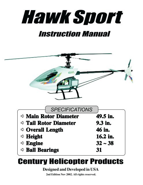
<strong>Hawk</strong> <strong>Sport</strong><br />
Instruction <strong>Manual</strong><br />
SPECIFICATIONS<br />
� Main Main Rotor Rotor Diameter Diameter 49.5 49.5 in.<br />
in.<br />
� Tail Tail Rotor Rotor Diameter Diameter 9.3 9.3 in.<br />
in.<br />
� Overall Overall Length Length<br />
46 46 in.<br />
in.<br />
� Height Height<br />
16.2 16.2 in.<br />
in.<br />
� Engine Engine<br />
32 32 ~ ~ 38<br />
38<br />
� Ball Ball Bearings Bearings<br />
31<br />
31<br />
Century Helicopter Products<br />
Designed and Developed in USA<br />
2nd Edition Nov 2002. All rights reserved.
2<br />
Table Table of of Contents Contents<br />
Contents<br />
Table of Contents & Introduction ...................................................................................................................... 1-2<br />
Required Items and Building Guide for Assembly .......................................................................................... 3-4<br />
Main Rotor Head, Washout & Swashplate Assembly Steps 1-6 ........................................... 5-7<br />
Start Shaft Assembly & Drive Train Assembly Steps 7-12 ....................................... 8-10<br />
Upper Side Frame Assembly Steps 13-15 ................................... 11-13<br />
Clutch, Clutch Bell, Fan, Shroud & Engine Mount Steps 16-17 ......................................... 14<br />
Fuel Tank & Lower Frames Assembly Step 18-21 .................................... 15-16<br />
Final Rotor Head Assembly, Muffler & Servo Frames Step 22-25 .................................... 17-18<br />
Landing Gear Step 26 ................................................ 19<br />
Tail Rotor Assembly Step 27-37 .................................... 19-24<br />
Pushrod, Radio & Servo Setup Step 38-44 .................................... 25-30<br />
Main Blades & Canopy Step 45-47 .................................... 30-31<br />
Radio Components & Balancing .......................................................................................................................... 32<br />
Setup and Installation of PG-2000 II Gyro ........................................................................................................ 33<br />
Radio Setup, Pitch,Throttle and Tail Rotor Curve Setup .......................................................................... 34-36<br />
Before Flying, Starting the Engine & Basic Hovering ............................................................................... 37-39<br />
Replacement Parts List & Parts Photos........................................................................................................ 40-44<br />
Introduction<br />
Introduction<br />
Congratulations on your purchase of Century Helicopter Product's latest version of our HAWK series RC<br />
helicopter model. The HAWK <strong>Sport</strong> helicopter is not only ideal for beginners new to the hobby, but also for<br />
the intermediate right on through to the expert and 3D flyers. A 6 channel helicopter radio is recommended as<br />
the bare minimum to take advantage of the helicopter programming included in these radios. The expert to 3D<br />
flyers would certainly be using a good 8 to 10 channel helicopter radio. You may wish to check with us or your<br />
local dealer for compatible components.<br />
Warning<br />
Warning<br />
This radio controlled model is not a toy! It is a precision machine requiring proper assembly and setup to<br />
avoid accidents. It is the responsibility of the owner to operate this product in a safe manner as it can inflict<br />
serious injury . It is recommended that if you are in doubt of your abilities, seek assistance from experienced<br />
radio control helicopter modelers and associations. As manufacturer, we assume no liability for the use of<br />
this product.<br />
Pre-assembly Pre-assembly Information<br />
Information<br />
Information<br />
Upon opening the kit, all the major component parts are packaged in numbered bags to correspond to specific<br />
sections of the manual, greatly facilitating assembly. Various assemblies have been pre-assembled, only<br />
requiring the final assembly and installation of the various sub-assemblies. The screws and nuts required for<br />
each step are packaged in the same bag as the parts for that step. Be careful not to lose any of the hardware<br />
when opening each bag. Care has been taken in filling and packing of each bag. However mistakes do happen,<br />
if there is a parts shortage or any hardware missing, please feel free to contact us at:<br />
Century Helicopter Products 523 Sinclair Frontage Road, Milpitas, CA 95035 USA<br />
Fax:408-942-9524 web: www.centuryheli.com e-mail: info@centuryheli.com
6 Channel Helicopter Radio or Equivalent.<br />
Main Blade Pitch Gauge<br />
w/PaddleGauge<br />
#CN2026<br />
5.5mm & 7mm nut drivers,<br />
Phillips Screw Driver,<br />
3mm & 4mm hex drivers<br />
Ball Link<br />
Plier<br />
#CN2034<br />
Allen Key Set CNBN10946<br />
Necessary Necessary Items Items “Not “Not Included” Included” in in the the kit.<br />
kit.<br />
PG2000 II dual rate piezo gyro<br />
CN2018 (or eqivalent)<br />
32-38 Helicopter Engine<br />
Necessary Necessary Tools Tools for for for Assembly Assembly and and Adjustments<br />
Adjustments<br />
Needle Nose Plier<br />
& Cutter Pliers<br />
4 Way Wrench<br />
#CN2031<br />
Hobby<br />
Scissors<br />
Metric<br />
Ruler<br />
Hobby Knife<br />
15% or 30%<br />
Heli Fuel<br />
Whip Antenna<br />
Remote Glow Adapter<br />
CN2222<br />
*Optional Tune Muffler<br />
#CN3033<br />
12Volt Start Battery<br />
Fuel<br />
Line<br />
Glow Driver w/Charger<br />
Fuel Filter Glow Plug<br />
Tie-Wraps<br />
Servo Tape<br />
Locktite<br />
CN2025B<br />
12Volt<br />
Starter<br />
Eletric or Hand<br />
Fuel Pump<br />
CN2024T<br />
Lubrication<br />
3
This manual has been written for the <strong>Hawk</strong> <strong>Sport</strong> helicopter kit CN1000B. This instruction manual<br />
covers the full step by step construction of the kit as a supplement to the Quick Start Guide. The <strong>Hawk</strong><br />
<strong>Sport</strong> 80% assembled helicopter can be assembled in just 3 hours by simply following the Quick Start<br />
Guide and referencing this manual on steps that are more complicated.<br />
Every attempt has been made to ease the assembly of your kit, at each step where there are complex<br />
assemblies you can read the detailed description here while following the pictures in the Quick Start Guide.<br />
Remember to take a few minutes before each step to carefully examine the step in order to become familiar<br />
with the parts and assembly sequence before beginning that step.<br />
4<br />
<strong>Hawk</strong> <strong>Hawk</strong> <strong>Sport</strong> <strong>Sport</strong> <strong>Construction</strong> <strong>Construction</strong> <strong>Manual</strong><br />
<strong>Manual</strong><br />
Symbols used to help assist you in building the kit:<br />
Full Scale<br />
Drawing<br />
Apply<br />
oil<br />
Special<br />
Attention<br />
Remove oil<br />
residue from<br />
fasteners before applying<br />
any threadlock agent.<br />
Repeat Steps<br />
as specified<br />
Apply<br />
threadlock<br />
Apply JB<br />
Weld<br />
Tap holes with<br />
machine screws<br />
before installing steel<br />
balls in plastic.<br />
The The The tools tools and and materials materials listed listed below below are<br />
are<br />
the the minimum minimum minimum needed needed needed to to build build the the helicopter:<br />
helicopter:<br />
Screwdrivers - Slotted and Phillips head.<br />
Long-Nosed Pliers.<br />
Allen Wrenches - 1.5mm, 2.0mm, 2.5mm.<br />
( supplied in kit ) + 3.0mm<br />
Appropriate Socket Wrench<br />
(glow plug wrench for engine shaft nut)<br />
Hobby Scissors<br />
Double Sided Foam Tape ( 1/16" - 3/32" )<br />
Foam Rubber ( radio packing )<br />
JB Weld ( bond clutch lining )<br />
Thread lock liquid (e.g. Locktite)<br />
Hobby Grease ( Super Lube )<br />
Oil to lubricate sliding shafts.<br />
"Y" Harness for 4 Ch Airplane Radio with 5 servo<br />
Partially<br />
tighten<br />
Purchased<br />
Separately<br />
Apply<br />
Grease<br />
Tap holes with<br />
machine screws<br />
before installing self tap<br />
screws in plastic.<br />
Recommended Recommended Tools Tools & & & Accessories<br />
Accessories<br />
Helpful<br />
Tip<br />
Cut away<br />
Shaded<br />
Portion<br />
Tap holes with<br />
machine screws<br />
carefully in plastic holes<br />
with bottoms.<br />
Hardware Description and Identification: M3x6 = 3x6mm and can refer to screws or ball bearings.<br />
M3x6 Phillips Machine Screw M3x6 Self Tapping Screw M3x10 Socket Cap Screw 3x7 Ball Bearing<br />
M - metric<br />
3 - diameter<br />
6 - length<br />
M - metric<br />
3 - diameter<br />
6 - length<br />
M - metric<br />
3 - diameter<br />
6 - length<br />
M - metric<br />
3 - inside<br />
6 - outside<br />
In In addition, addition, the the following following will will will make make assembly assembly and and setup<br />
setup<br />
easier, easier, and and and prove prove useful useful later later in in in your your model model model toolbox:<br />
toolbox:<br />
Part#CN2015 Hardened Tip Hex Screw Driver Set<br />
Part#CN2026 Pitch Gauge with Paddle Gauge.<br />
Part#CN2034 15 0 Curve Tip Ball link Pliers.<br />
Part#CN2052 Main Blade Balancer.<br />
Part#CN2054 Special Glow Plug Wrench Set.<br />
Part#CN2055 Ball Link Sizing Tool.<br />
Part#CN2070 Universal Flybar Lock.<br />
Part#CN2155 Piston Locking Tool.<br />
Part#CN2219 Ball Link Easy Driver.<br />
Part#CN2255 Control Rod Guage.<br />
Part#CNWI26555 5.5mm Nut Driver.<br />
Part#CNWI26570 7.0mm Nut Driver..
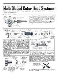
STEP STEP 1 1 Main Main Rotor Rotor Head<br />
Head<br />
From parts bag 1: Press the<br />
Damper Rubbers and the<br />
Guide Pins into the Head<br />
Block. Apply one drop of<br />
thin CA glue to the pins<br />
after they are fully seated.<br />
Install one M3x10 oilite<br />
bearing onto each side of<br />
the seesaw shaft and insert<br />
into the Head Block.<br />
Secure with the two M3x6<br />
self tapping screws.<br />
Optional SE<br />
Seesaw<br />
Ball<br />
Bearings<br />
CNBB1030 x 2<br />
STEP STEP 2 2 Seesaw Seesaw Assembly<br />
Assembly<br />
From parts bag 1: Insert one 3x7mm ball<br />
bearing into each bearing cup and insert<br />
into the offset plate. Following the numbered<br />
order, thread one M3x6 button head<br />
screw and one M3x6 Special ball through<br />
the offset plates into one tie bar. Slide the<br />
assembly onto the seesaw shaft and attach<br />
the other tie bar from the opposite side.<br />
Damper Rubber x 2<br />
[HI3181]<br />
Rotor head<br />
Block<br />
[HI3160B]<br />
Guide Pins x 2<br />
2.5x30 mm<br />
[HW3170A]<br />
Special Ball x 2<br />
[HI3167E] New completed rotor<br />
Bearing Cup x 2<br />
[HI3167D]<br />
Follow steps<br />
1, 2, & 3.<br />
1<br />
Tie Bar x 2<br />
[HI3167C]<br />
M3x6 Self<br />
Tapping<br />
Screw x2<br />
2<br />
Seesaw Shaft Set<br />
[HW3161A]<br />
3x7 Ball Bearing x 2<br />
[CNBB0730]<br />
Rotor Head<br />
from Step 1<br />
3<br />
Offset Plate x 2<br />
[HI3167B]<br />
head with symmetrical<br />
seesaw plates.<br />
M3x6 Button Machine<br />
Screw x 2 [HI3167E]<br />
Take notice of the location<br />
of the two steel balls on the<br />
offset plates.<br />
5
STEP STEP 3 3 Main Main Blade Blade Blade Grip Grip Grip Assembly Assembly<br />
Assembly<br />
From parts bag 1: Install one<br />
Long Ball and one Short Ball<br />
into the Bell Mixer, insert the<br />
slide tube into the bell mixer<br />
arm (Note: Note: the the oilite oilite oilite bearings<br />
bearings<br />
are are pre-installed<br />
pre-installed) pre-installed and secure<br />
onto the blade grip with one<br />
M3x16 Socket Cap screw and<br />
M3x7 Flat washer. Install two<br />
M5x13 Ball Bearings into each<br />
end of the blade grip assembly.<br />
Complete<br />
the second<br />
blade grip in<br />
exactly the<br />
same way.<br />
From parts bag 1: Insert the Feathering<br />
Shaft into the head block, slide one<br />
5X10mm Washer on each side of the shaft.<br />
Install the blade grip ( Note Note the the direction<br />
direction<br />
6<br />
Note, the long ball is installed pointing<br />
away from the the blade grip.<br />
Optional SE Ball<br />
Bearing Set<br />
replaces the two<br />
oilite bushings<br />
of of the the bell bell mixer mixer arm arm with with the the beveled<br />
beveled<br />
edge edge on on top top of of the the the blade blade grip grip )<br />
followed by one 4x10mm<br />
Washer, one 4x12mm Washer<br />
and one 4mm Locknut. Assemble<br />
Pushrod “I” x 2, measuring 28mm<br />
center to center distance<br />
following the table<br />
on page 25, and<br />
connect the seesaw<br />
ball to the long ball on<br />
the bell mixer.<br />
Bell Mixer<br />
Arm<br />
[HI3189]<br />
Main Rotor<br />
Blade Grip<br />
[HI3184]<br />
Long Ball<br />
[CNLR1016A]<br />
Top of blade<br />
grip has Bevel.<br />
STEP STEP 4 4 Feathering Feathering Spindle Spindle & & Blade Blade Blade Grips<br />
Grips<br />
Pushrod “I” will require a 26mm<br />
length for a 3D setup - see page 25.<br />
M5x10 Flat<br />
Washer x 2<br />
Feathering Shaft<br />
[HW3180]<br />
Side View<br />
Slide Tube<br />
M4x10 Flat<br />
Washer x 2<br />
28mm or 26mm<br />
Short Ball<br />
[CNLR1014]<br />
M3x7 Flat<br />
Washer<br />
Long Ball<br />
5x13 Ball<br />
Bearing x 2<br />
[CNBB1350]<br />
M3x16 Socket<br />
Cap Screw<br />
Oilite Bushing x 2<br />
M4 Locknut x 2<br />
Short Ball<br />
Repeat 2<br />
Times.<br />
M4x12 Flat<br />
Washer x 2<br />
Pushrod (I x 2)<br />
( see page 25 for<br />
referrence)
STEP STEP STEP 5 5 Flybar, Flybar, Paddles Paddles & & Flybar Flybar Control Control Arms<br />
Arms<br />
From parts bag 1: Slide and center the Flybar through the seesaw arm assembly. Install one Steel ball (care<br />
must be taken when inserting the M2 Steel Ball, it is best to turn 1/2 in - then 1/2 out (like tapping a hole) until<br />
the ball is fully seated) onto each flybar control arm. Slide the M3x3 Spacer and Flybar Control Arm onto the<br />
flybar. Loosely tighten the control arms with two M4x5 Set Screws. Using a ruler, check the distance between<br />
the end of the flybar and the control arm and adjust until the lengths are the same and there is no free play<br />
between the control arms and the rotor head. Slide the Flybar Weight (Note: the flat end of the weight faces<br />
the paddle) and thread on the Flybar Paddle until all the threads are covered onto the flybar and align the<br />
paddles parallel. Again using the ruler, rotate one paddle or the other to get equal distances, remember the<br />
leading edge of the paddles turn clockwise and finally apply threadlock on the two M3x3 Set Screws to secure<br />
the flybar weights. The last step is to secure the flybar control arms, remove one set screw at a time, apply<br />
threadlock and tighten in place.<br />
Flybar Control Arm x 2<br />
Flybar Paddles<br />
Steel Ball x 2<br />
& Weights<br />
[HI3176]<br />
[HI3179] x 2<br />
M3x3 Set<br />
Screw x 2<br />
M4x5 Set<br />
Screw x 2<br />
Leading Edge<br />
Spacer M3x3<br />
[HI3167D]<br />
A=B=A<br />
A B A<br />
Clockwise<br />
Align each paddle 'A' to be parallel with the flybar Rotation<br />
control arms 'B'. This is made very simple with the optional pitch and paddle gauge CN2026<br />
STEP STEP 6 6 Washout Washout Unit Unit & & Swashplate<br />
Swashplate<br />
Attach two Medium Balls to the Washout Mixing<br />
Arms ( Note, Note, attach attach attach from from the the flat flat flat side side of<br />
of<br />
the the arm). arm<br />
arm Secure the semi-assembled mixing<br />
arms onto the Washout Hub using one slide tube<br />
inserted from the flat side and secured using Medium<br />
one 3x16mm Socket Cap Screw and one Black Ball x 2<br />
3x7mm Flat Washer per arm (note, note, use<br />
use [CNLR1015]<br />
the the left left side side hole hole hole on on on the the the hub). hub<br />
hub After<br />
attaching the balls to the swashplate, press<br />
the radius link onto the inner short balls on<br />
the Swashplate.<br />
Medium<br />
Steel Ball x 2<br />
[CNLR1015]<br />
Swashplate Assembly [HI3146B]<br />
Radius Link &<br />
M2x12 Pin<br />
[HI3152A]<br />
Short Steel<br />
Ball x 5<br />
[CNLR1014]<br />
Leading Edge<br />
M3x7 Flat<br />
Washer x 2<br />
Optional Head<br />
Button<br />
CN2215<br />
Note: Secure oilite bushings<br />
to hub with thin CA<br />
Flybar [HW3173]<br />
* packed with<br />
tailboom<br />
For balancing of<br />
rotor head see Final<br />
Adjustments<br />
Washout Hub<br />
Assembly<br />
[HI3152C]<br />
Slide Tube x 2<br />
Oilite<br />
Bushing x 2<br />
M3x16 Socket<br />
Cap Screw x 2<br />
Starting with the inside race, apply threadlock<br />
and attach two short balls (Tip Tip 1 11)<br />
1 directly<br />
across from each other, similarly attach two<br />
medium balls to the remaining holes. Attach<br />
the three short balls (Tip Tip 2 22)<br />
2 to the outside<br />
race. The rear location is not used now.<br />
7
STEP STEP 7 7 Starting Starting Shaft Shaft Shaft Bearing Bearing Blocks<br />
Blocks<br />
From parts bag 2: the<br />
Start Shaft Guide Blocks<br />
are pre-assembled. Slide<br />
the Starter Shaft through<br />
one of the block assemblies<br />
with the M5x11 Ball<br />
Bearing facing up then<br />
slide the M5 flat washer,<br />
spring and finally the<br />
M5x10 Collar<br />
Hex Start<br />
Adapter<br />
[CN0402]<br />
8<br />
Pre-Assembled<br />
M2x5 Flat<br />
Washer<br />
5x11 Ball<br />
Bearing x 2<br />
[CNBB1150]<br />
Start Shaft<br />
Guide Block x 2<br />
[HI3007]<br />
Hex Starter Extension (Optional Part#CN0426)<br />
M4x4 Set<br />
Screw x 2<br />
M3x4 Set<br />
Screw<br />
M2x5 Self<br />
Tapping Screw<br />
M5x10<br />
Collar<br />
Spring<br />
M5x10 Flat<br />
Washer<br />
Start Shaft<br />
Hex Type<br />
Starter Shaft Set<br />
Pre-Assembled<br />
Pre-Assembled<br />
[HW3005A]<br />
STEP STEP STEP 8 8 Engine Engine Start Start Shaft<br />
Shaft<br />
From parts in bag 2: After sliding the top bearing<br />
block in place, attach the hex start adapter to the<br />
starting shaft HW3005A using threadlock on both<br />
the shaft and the two two M4x4 M4x4 M4x4 set set screws screws. screws Align<br />
one set screw to fit into the machined indentation<br />
in the hardened start shaft. Apply some lubricant<br />
on the shaft after assembly to ensure smooth<br />
vertical movement inside the inner races of the<br />
bearings when engaging and disengaging of the<br />
start system.<br />
When removing the hex start wand after the<br />
engine is started, it is recommended that you<br />
use a two step procedure.<br />
#1: Lift the hex wand upwards just enough to<br />
disengage the start system while keeping the<br />
wand inserted in the hex coupler (CN0402).<br />
#2: After the coupler has stopped turning, then<br />
remove the wand from the hex coupler.
STEP STEP 9 9 Tail Tail Transmission Transmission Output Output Gear<br />
Gear<br />
From parts bag 2: Assemble the Tail<br />
Transmission Output Gear assembly.<br />
Install the E-Ring (be careful not to lose<br />
it, it can easily spring away during installation).<br />
Slide the two Ball Bearings onto<br />
the front of the Tail Rotor Output Shaft.<br />
Using threadlock, insert one 3x4mm Set<br />
Screw into the gear, Note where the flat<br />
spot is on the shaft, slide the gear on and<br />
tighten the set screw (Make Make sure sure the the set<br />
set<br />
screw screw is is positioned positioned over over the the flat flat spot spot). spot<br />
STEP STEP 10 10 Counter Counter Gear Gear Assembly<br />
Assembly<br />
From parts bag 2: Assemble the<br />
engine drive gear assembly. Start by<br />
inserting the guide pin into the hole in<br />
the end of the Drive Shaft. Insert the<br />
shaft through the Counter Gear<br />
(make make sure sure sure the the pin pin pin is is fully fully seated seated seated in<br />
in<br />
the the recessed recessed slot slot at at the the bottom bottom of<br />
of<br />
the the gear gear gear) gear gear then slide the two M5x13<br />
Ball Bearings followed by the two<br />
M5x7 spacers. Using locktite, insert<br />
one 3x4mm Set Screw into the Alloy<br />
Drive Gear, then slide the gear onto<br />
the shaft taking care to position the<br />
set screw over the flat spot on the<br />
shaft. Secure the drive gear to the<br />
shaft.<br />
Careful setup in the drive train<br />
will ensure trouble free operation.<br />
M3x4 Set Screw<br />
(small hex key)<br />
Tail Rotor Output<br />
Gear [HW3057]<br />
Alloy Drive Gear<br />
[HW3045]<br />
M5x7<br />
Spacer x 2<br />
Counter Gear 55T<br />
[HI3040]<br />
Test fit the gear assembly into one half of the upper side frames.<br />
While holding the alloy drive gear, try to slide the counter gear<br />
up and down on the shaft. Adjust for as little vertical play as<br />
possible. It is normal and necessary to have a small amount of<br />
vertical play to allow for expansion due to heat during operation.<br />
A small amount of red locktight to the top of the counter shaft,<br />
between it and the pinion gear will make for a more secure fit.<br />
Only use blue locktite on the set screw. A small amount of the<br />
blue locktight can be applied carefully on the shaft between each<br />
bearings and the shaft. Warning Warning, Warning do not get any shaftlock in<br />
the bearing as damage to the bearing may result.<br />
Tail Transmission<br />
Output Shaft<br />
[HW3059]<br />
5x13 Ball<br />
Bearings x 2<br />
[CNBB1350]<br />
E - Ring<br />
M3x4 Set<br />
Screw (small<br />
key)<br />
5x13 Ball<br />
Bearings x 2<br />
[CNBB1350]<br />
Drive Shaft<br />
[HW3042]<br />
M2x12 Pin<br />
[HI3040]<br />
9
STEP STEP 11 11 11 Main Main Main Gear Gear & & Shaft Shaft Shaft Assembly<br />
Assembly<br />
From parts bag 2: The Main Gear is preassembled<br />
with the Auto-Rotation Bearing<br />
installed. Insert the bottom end through the<br />
auto rotation gear assembly, align the holes and<br />
secure the Main Shaft using one 3x16mm<br />
Socket Cap Screw and one 3mm Locknut.<br />
You can temporarily insert main shaft,<br />
main shaft bearing spacer & bearing,<br />
stopper and head block screw to keep them<br />
from getting lost!<br />
* Do not apply threadlock here. *<br />
10<br />
Completed<br />
Main Gear &<br />
Main Shaft<br />
STEP STEP 12 12 Elevator Elevator Lever Lever Assembly<br />
Assembly<br />
From parts bag 2: Insert the long<br />
threaded axle and one M3x7 ball<br />
bearing from each end of the<br />
bellcrank. Slide one short spacer<br />
over one 3x30mm Socket Cap<br />
screw and attach to the threaded<br />
axle ( do do not not not use use threadlock<br />
threadlock<br />
here! here! here!), here! repeat for other side. The<br />
2x16mm pin is assembled, just<br />
insure the elevator radius link<br />
moves freely against the<br />
Bellcrank. Thread one short<br />
steel ball into the elevator arm.<br />
CNQSC04<br />
Optional machined<br />
ball bearing<br />
elevator arm w/<br />
adjustable ball link.<br />
Elevator<br />
Bellcrank<br />
[HI3032B]<br />
Auto-<br />
Rotation<br />
Bearing<br />
[HW3050]<br />
Pre-<br />
Assembled<br />
M3 Locknut<br />
Elevator<br />
Link Only<br />
[HI3032C]<br />
M2x16 Pin<br />
Short Steel Ball<br />
M2 [CNLR1013]<br />
Short Spacer<br />
x 2<br />
M3x16 Socket<br />
Cap Screw<br />
Only assemble, do not<br />
use threadlock now!<br />
Main Shaft<br />
[HW3053A]<br />
Main Gear<br />
[HI3056]<br />
Long Threaded Axle<br />
M3x7 Ball<br />
Bearing x 2<br />
[CNBB0730]<br />
M3x30 Socket<br />
Cap Screw X 2
STEP STEP 13 13 13 Upper Upper Side Side Side Frames<br />
Frames<br />
From parts bag 2: Install two M4x5 Set Screws (note-do note-do not not apply apply apply locktite locktite at at at this this time time) time into the Mast<br />
Stopper (note note that that the the the raised raised raised inner inner inner diameter diameter diameter must must must face face face the the the ball ball ball bearing) bearing)<br />
bearing) and slide the mast stopper<br />
on the main shaft followed by one M10x19 Ball Bearing and one M14x19 Spacer (the the spacer spacer must<br />
must<br />
be be installed installed on on on top top top of of of the the the bearing). bearing<br />
bearing Slide one M8x19 Ball Bearing from the bottom of the main shaft.<br />
Attach the starter shaft assembly to the left side upper side frame with four M3x12 Self Tapping<br />
Screws (Tip Tip 2 22-<br />
2 observe observe the the correct correct correct orientation orientation orientation of of of the the the block block block assemblies). assemblies<br />
assemblies Position the main gear/<br />
main shaft assembly, (note note the the the orientation orientation of of the the mast mast stopper, stopper, the the the raised raised inner inner diameter diameter should<br />
should<br />
be be facing facing facing upward, upward, upward, towards towards towards the the the inner inner inner race race race of of of the the the top top top bearing) bearing<br />
bearing the counter gear assembly and the<br />
tail transmission output shaft assembly in their designated locations (see diagram below) on the upper right<br />
side frame (make make make sure sure the the bearings bearings are are are fully fully seated seated in in the the recesses recesses). recesses<br />
M3x12 Self Tapping<br />
Screws x 4<br />
3<br />
3<br />
Start Shaft<br />
Assembly<br />
from Step 8<br />
Upper Side Frame<br />
[HI3107]<br />
Counter Gear<br />
Assembly from<br />
Step 10<br />
Tail Transmission<br />
Output Gear Assembly<br />
from Step 9<br />
M19x14 Spacer<br />
[HI3107A]<br />
Mast Stopper<br />
[HW3054A]<br />
M8x19 Ball<br />
Bearing<br />
[CNBB1980]<br />
M10x19 Ball<br />
Bearing<br />
[CNBB1019]<br />
M4x4 Set<br />
Screw (med<br />
hex key) x 2<br />
1<br />
Main Gear<br />
Assembly<br />
from Step 11<br />
Be Be careful careful when when tightening tightening the the eight eight 3x12mm 3x12mm self self tapping tapping screws screws screws into into the the start start shaft<br />
shaft<br />
block block assemblies assemblies as as excessive excessive force force can can can strip strip the the plastic plastic holes.<br />
holes.<br />
11
STEP STEP 14 14 14 Upper Upper Frame Frame Assembly Assembly<br />
Assembly<br />
From parts bag 2: Insert the two long Hex Spacers at the specified locations in the diagram (note: ote: the<br />
the<br />
front front front hex hex spacer spacer spacer is is is installed installed installed into into into the the the forward-most forward-most forward-most hole). hole)<br />
hole) Install the upper left side frame, taking<br />
care that the bearings are aligned with the mating recesses and secure the frames with four M3x35 Socket<br />
Cap Screws (Tip Tip 1-do 1-do not not use use threadlock threadlock threadlock when when using using locknuts locknuts) locknuts through the main shaft bearing block<br />
positions and four M3 locknuts. It is advised to position the elevator assembly between the side frames at<br />
this time in order to reduce the amount of installation positioning later.<br />
While pushing down on the main shaft (make sure the main gear rotates freely), push the mast<br />
stopper against the upper ball bearing insuring that the side of the stopper with the raised inner portion is<br />
facing upwards, Apply threadlock to the set screws and tighten in place. Attach the remaining four<br />
3x12mm Self Tapping Screws (Tip Tip Tip 4 44)<br />
4 to the starting shaft blocks.<br />
12<br />
M3 Locknut x 4<br />
M4x4 Set<br />
Screw x 2<br />
Elevator Assembly<br />
Upper Side<br />
Frames L& R<br />
[HI3107]<br />
Long hex spacers<br />
[HW3127A] x 2 M3x35 Socket<br />
M3x12 Self<br />
Tapping<br />
Screws x 4<br />
4<br />
Cap Screws x 4<br />
1<br />
The gear mesh between the main gear and the tail transmission output shaft may be a snug fit at<br />
first, but it will become smooth after a few flights. This is the normal wear in process.
STEP STEP 15 15 Collective Collective Collective and and Aileron Aileron Levers<br />
Levers<br />
From parts bag 2: Press in two M6x10 ball bearings into the front side frames for the collective axle.<br />
Insert two M3x10 Socket Cap Screws through the right (R) Collective arm and attach the collective axle<br />
(notice that the round 6mm collective axle is attached at the middle hole) and hex spacer using threadlock.<br />
Slide the assembly through the ball bearings in the upper side frames from the right. Using threadlock<br />
attach the Left Collective Arms with two M3x10 Socket Cap Screws. Tighten the screws insuring the<br />
collective lever moves freely with no side to side play. Install one M3 Short Ball on to the collective lever<br />
using threadlock.<br />
The left Aileron Bellcrank has two oilite bearings pre-installed into the bellcrank, install the two<br />
Short Balls to the flat side and insert the slide tube through the bellcrank using a small amount of lubricant<br />
(the the bellcrank bellcrank bellcrank is is is offset, offset, make make make sure sure sure the the the slide slide slide tube tube tube is is is inserted inserted inserted from from from the the the offset offset offset side). side<br />
side Starting on the<br />
left side, remove the 3x30mm Socket Cap Screw and short spacer from the elevator bellcrank (previously<br />
assembled in Step 12), slide the left aileron assembly onto the screw and insert through the left collective<br />
lever. Apply threadlock to the end of the screw threads now and slide on the short spacer before tightening<br />
into the elevator bellcrank axle. Repeat for the other side. Slide one Threaded Extension Rod through<br />
the upper position of the tail output bearing recess and secure two Canopy Standoffs (one per side) using<br />
threadlock.<br />
M3x30 PH Socket<br />
Cap Screw x 2<br />
(from Step 12)<br />
M3x10 Socket<br />
Cap Screws x 4<br />
Aileron<br />
Bellcrank<br />
[ HI3031A ]<br />
M6 x 10 Ball<br />
Bearing x 2<br />
[CNBB1060]<br />
R<br />
Slide Tube<br />
Repeat<br />
twice<br />
Short Ball x 4<br />
[CNLR1014]<br />
Collective<br />
Hex Spacer<br />
Short Ball<br />
[CNLR1014]<br />
Canopy<br />
Standoff x 2<br />
[HW3127A]<br />
Collective Axle<br />
(6mm dia)<br />
Short Spacer<br />
L<br />
Upper frame<br />
assembly from<br />
Step 14<br />
Threaded<br />
Extension<br />
Rod<br />
Slide Tube<br />
Flat Side<br />
Collective<br />
Levers<br />
[HW3024]<br />
13
STEP STEP 16 16 16 Clutch, Clutch, Fan Fan & & Engine Engine Mounting<br />
Mounting<br />
From parts bag 3: Remove all parts<br />
from the engine crankshaft until you<br />
can see the front ball bearing. Install<br />
the M9x13 Flat washer (or washer<br />
provided by engine manufacturer),<br />
insert the Ball Bearings into the<br />
clutch bell assembly and place on the<br />
crankshaft. Clean the threads on the<br />
crankshaft and on the clutch, carefully<br />
apply blue threadlock on the<br />
last 6mm of crankshaft threads<br />
nearest the bearing (be careful not<br />
to get threadlock into the ball<br />
bearings) and on the threads in the<br />
clutch. Thread the clutch onto the<br />
crankshaft until the crankshaft can<br />
be seen through the top. Insert the<br />
fan, keying it to the clutch. Wrap a<br />
cloth over the fan (provides grip to<br />
the fan without breaking the fins)<br />
and tighten until the clutch stops,<br />
torque an additional 1/16 of a turn.<br />
[CN2155 Optional Parts] makes this<br />
easier. Secure the fan with the<br />
M6.5x13 Washer and the engines<br />
prop nut onto the crankshaft. Apply<br />
Apply<br />
some some high high strength strength red<br />
red<br />
threadlock threadlock to to the the prop prop nut nut to<br />
to<br />
insure insure its its security security<br />
security Again only<br />
torque the nut 1/16th of a turn more.<br />
STEP STEP 17 17 Engine Engine Mount<br />
Mount<br />
14<br />
Engine<br />
Nut<br />
M6.5x13 Flat<br />
Washer<br />
Cooling Fan<br />
[HI3009]<br />
Clutch<br />
Shoes<br />
[HW3011]<br />
Clutch Bell<br />
[HI3010]<br />
M9x13 Flat<br />
Washer<br />
Using threadlock, secure the engine assembly onto the<br />
engine mount using four 3x16mm Socket Cap Screws.<br />
From bag 4, install the Throttle Extension by removing<br />
the arm supplied on the engine. The arm has to be<br />
repositioned to get equal throw, both open and closed<br />
from 50% as per the diagram below.<br />
Throttle arm on Carburator<br />
50%<br />
Full Open Full Closed<br />
M12x18 Ball<br />
Bearing x 2<br />
[CNBB1218]<br />
Replacement<br />
Clutch Lining<br />
[CN2020L]<br />
M3x16<br />
Socket Cap<br />
Screws x 4<br />
Engine<br />
Assembly<br />
with Fan<br />
Thrust Washer<br />
or M9x13 FW<br />
Engine ball<br />
bearing<br />
exposed.<br />
During final assembly<br />
wipe all traces of oil<br />
or grease from the<br />
inside surface of the clutch<br />
lining. Any grease here can<br />
cause a meltdown.<br />
(Optional Parts)<br />
CN2153 Throttle Extension<br />
for OS32SXH<br />
Engine Mount<br />
[HW3017]<br />
Throttle Extension<br />
[HW3204]
STEP STEP 18 18 Fuel Fuel Tank Tank & & Fittings<br />
Fittings<br />
From parts bag 3: Insert the two pieces of aluminum tubing through the large cap, rubber stopper and<br />
small cap, bend the long aluminum vent tube upwards (make sure the tube comes to the top of the fuel<br />
tank) and attach the short piece of fuel line and clunk to the short straight piece of tubing. Test fit the<br />
assembly into the Fuel Tank and make sure that the clunk reaches to about 1/8” from the back of the tank<br />
and can move around freely. Insure the vent tube is near the top of the tank but does not touch it. Install<br />
the tie wrap around the outside of the rubber cap. Finally tighten the long self tapping screw to seal the<br />
tank.<br />
Rubber<br />
50mm Fuel<br />
Small Cap<br />
Stopper<br />
Wrap the tie- line inside Large Cap<br />
wrap around tank with<br />
Vent Tube - bent<br />
the outside and Clunk.<br />
and ends near the<br />
M2.5 x 18 Self<br />
secure.<br />
top of the tank.<br />
Tapping Screw<br />
Note: The fuel tank opening is off-center and should<br />
be installed upwards to align closer to the carburetor.<br />
STEP STEP 19 19 Lower Lower Frame Frame Assembly<br />
Assembly<br />
From parts bag 3: Slide the Fuel Tank into position and assemble the Lower Frames with four M3x16 Self<br />
Tapping Screws into the gyro plate. NOTE NOTE: NOTE Lay the bottom of the sideframes on a flat surface to align the<br />
two sides when tightening the screws. The fuel tank opening should be installed with the fittings on the<br />
right side to insure they are on the side of the carburetor fuel inlet. The vent tube can later be plug into the<br />
muffler pressure fitting (see step 23) or left open to the air as some may prefer. The fuel pickup tube will be<br />
attached to carburator. (see step 21)<br />
Lower Side<br />
Frames<br />
[HI3112] x 2<br />
Fuel pickup tube goes to<br />
engine carburator<br />
Gyro Tray<br />
[HI3112]<br />
Vent Tube left open<br />
to the air or can go<br />
to muffler pressure<br />
fitting<br />
Fuel Tank [HI3138A]<br />
10 oz. Fuel<br />
Tank<br />
[HI3138A]<br />
Pickup tube -<br />
straight<br />
M3x16 Self<br />
Tapping<br />
Screws x 4<br />
15
STEP STEP 20 20 Upper Upper & & Lower Lower Frames<br />
Frames<br />
Using threadlock, attach the lower<br />
frame assembly to the upper frame<br />
assembly with four M3x16 Socket Cap<br />
Screws and four M3x7 Washers.<br />
STEP STEP 21 21 Engine Engine Cooling Cooling Fan Fan Shroud<br />
Shroud<br />
Assemble the Lower<br />
Cooling Fan Shroud over the<br />
head of the engine using parts<br />
from bag 3. Assemble the two<br />
halves using the five M2.6x10 Self<br />
Tapping Screws. Loosely install the<br />
engine assembly into the lower side frames<br />
using four 3x16mm Socket Cap Screws<br />
and four 3x7mm Large Flat Washers. Position<br />
the lower shroud to overlap the upper shroud,<br />
adjust the engine height by sighting from the side.<br />
Slide the engine upwards until the clutchbell gear is<br />
properly meshed with the counter gear, then threadlock the screws in place. At this time, plug the fuel line<br />
to the carburator (Tip (Tip 1 1 -installing a fuel filter between tank and carburator will help prevent any fuel<br />
contamination from entering the carburator and causing engine failure). Now check the starting shaft,<br />
loosen the collar and adjust its height to insure the start shaft can fully disengage from the cooling fan.<br />
NOTE: NOTE: use threadlock on set screws of collar.<br />
Engine Assembly<br />
installed onto<br />
mount.<br />
For proper gear<br />
mesh, insure the<br />
counter gear has<br />
mimimum vertical<br />
play on it's<br />
shaft.<br />
16<br />
Cooling Fan<br />
Shroud<br />
[HI3020]<br />
Upper Frame<br />
Assembly<br />
M3x16 Socket<br />
Cap Screws x 4<br />
Lower Frame<br />
Assembly<br />
M3x16 Socket<br />
Cap Screws x 4<br />
M3x7 Flat<br />
Washer x 4<br />
M2.6x10 Self<br />
Tapping Screws<br />
x 5<br />
M3x7 Flat<br />
Washers x 4
STEP STEP 22 22 22 Final Final Rotor Rotor Head Head Assembly Assembly<br />
Assembly<br />
M3x16<br />
Socket<br />
Cap Screw<br />
&<br />
M3 Locknut<br />
Swashplate &<br />
Washout<br />
Assembly<br />
from Step 6<br />
Short Steel Ball<br />
Completed Rotor<br />
Head Assembly from<br />
Step 5<br />
Main Frame Assembly from Step 21<br />
Speed Torpedo<br />
Muffler CN3040<br />
Long Steel Ball<br />
Muffler<br />
Pressure<br />
tap<br />
Optional CN3055H High Performance<br />
Tuned Pipe available.<br />
Remove the M3x16 Socket Cap Screw from the top of the<br />
main shaft. Slide the swashplate and washout assembly<br />
(from from Step Step 6) 6<br />
6 onto the main shaft and snap the elevator<br />
lever arm onto the single front ball on the swashplate.<br />
Slide the completed rotor head assembly (from from Step Step 5 55)<br />
5<br />
onto the shaft and align the hole in the head block with<br />
the hole in the top of the main shaft. Insert one M3x16<br />
Socket Cap Screw and 3mm locknut (from from Bag Bag 2 22)<br />
2 to<br />
secure the two. (Note: (Note: (Note: Make Make sure sure the the pins pins in in the<br />
the<br />
rotor rotor head head block block are are aligned aligned and and inserted inserted into into the<br />
the<br />
holes holes in in the the washout washout washout unit.) unit.)<br />
unit.) Apply some oil sparingly<br />
to the washout hub assembly to insure they slide<br />
smoothly.<br />
Following assembly, move the collective lever<br />
fore and aft to the endpoints. The swashplate<br />
and washout unit should be very smooth<br />
throughout the movement range. If not, inspect<br />
the fit of the washout guide to the pins in<br />
the rotor head, these pins can be bent slightly if<br />
binding. Also check the collective axle, the<br />
screws here may be too tight. The fit of the ball<br />
links sometimes can cause binding, with time<br />
these will break in. These few points are the<br />
most common which will cause servo strain<br />
leading to premature wear and can make the<br />
collective control a little vague.<br />
STEP STEP 23 23 Attaching Attaching the the Muffler<br />
Muffler<br />
Attach the muffler to the engine with the screws<br />
provided with the muffler (Tip Tip 1 11-<br />
1 using hi-temp<br />
threadlock). Attach the pressure tap to the top of<br />
the muffler and the M4x6 Phillips Machine screw<br />
to the bottom hole in the muffler, remember to use<br />
hi-temp RTV sealer or threadlock on these parts.<br />
For a good seal between the muffler and the<br />
exhaust port, use a gasket made from thin<br />
aluminum, brass or exhaust gasket material. To<br />
properly seal the fit, after running the engine for<br />
several minutes on the first run, shut down the<br />
engine and re-tighten the bolts, while the engine<br />
is still hot. The extra 1/8 to1/4 turn on the bolts<br />
will seat the muffler in place.<br />
17
STEP STEP 24 24 Servo Servo Servo Frame Frame Assembly<br />
Assembly<br />
From parts bag 5: Assemble the servo tray using eight M3x16 Self Tapping Screws. This is a good time to<br />
install the collective and throttle servos (note orientation) from the inside inside inside of the left servo frame. (Note, Note, Note,<br />
use use the the rubber rubber rubber grommets grommets provided provided with with the the servos, servos, you you you can can use use the the the screws screws screws that that came came with<br />
with<br />
your your servos servos or or or the the the screws screws screws provided provided provided in in in the the the kit). kit<br />
kit Attach the rudder (yaw), aileron (roll cyclic) and<br />
elevator (fore/aft cyclic) servos insuring proper orientation, to the top servo tray. Attach the canopy mount<br />
using two M3x30 Phillips Machine Screws through the top of the lower servo tray, through the plastic<br />
spacer and into the canopy mount.<br />
18<br />
Rudder Servo<br />
M3x16 Self<br />
Tapping<br />
Screws x8<br />
R<br />
Aileron Servo<br />
Canopy<br />
Mount<br />
[HI3129]<br />
M3x30<br />
Machine<br />
Screws x 2<br />
STEP STEP 25 25 25 Main Main Mechanics<br />
Mechanics<br />
Attach the servo tray assembly<br />
to the mechanics using<br />
four M3x10 Self Tapping<br />
Screws, two M3x20 Socket<br />
Cap Screws and two M3<br />
Washers. The two Locknuts<br />
for the cap screws are<br />
unserted into the recess inside<br />
the bottom of the fan shroud .<br />
Throttle<br />
Servo<br />
M2.3x12 Self<br />
Tapping Screws<br />
x 20<br />
Elevator Servo<br />
Collective<br />
Servo<br />
Servo Tray Set<br />
[HI3115]<br />
L<br />
Recess for M3<br />
Locknut inside<br />
fan shroud.<br />
M3x10 Self<br />
Tapping<br />
Screws x 4<br />
M3x20 Socket Cap<br />
Screws , M3 washer &<br />
M3 Locknut
STEP STEP 26 26 Landing Landing Landing Gear<br />
Gear<br />
From parts bag 6: Assemble the landing gear by sliding the Aluminum Skids through the Struts, start the<br />
four M3x5 Set Screws into the struts, but do not tighten at this time. (Do not use any threadlock). Set the<br />
distance from the rear of the skid to the strut at 25 to 30mm. Attach the landing gear to the main mechanics<br />
using four M3x16 Socket Cap Screws and locknuts. Now Now set set the the skids skids into into into their their desired desired position<br />
position<br />
and and tighten tighten the the 4 4 set set screws. screws. Be Be careful careful not not to to strip strip the the the holes holes in in the the struts.<br />
struts.<br />
After finishing the radio<br />
installation, thread the<br />
antenna wire from the radio tray<br />
through the plastic tube and tie a slip<br />
knot with a small elastic to the end of<br />
the antenna wire. Hook the end of the<br />
elastic to the vertical tail fin.<br />
Aluminum Skids<br />
[HW3123] x 2<br />
From parts bag 7: Notice that the<br />
Tail Rotor Drive Shaft has 2 holes,<br />
one through the shaft<br />
and one drilled partially<br />
into the shaft. Slide the<br />
SMALLER SMALLER SMALLER Bevel Gear with the<br />
Antenna Plastic Guide Tube<br />
STEP STEP 27 27 Tail Tail Output Output Shaft<br />
Shaft<br />
M3x16<br />
Socket Cap<br />
Screws x 4<br />
teeth facing inward from the end<br />
with the through hole. Position the<br />
gear by aligning the holes. Press<br />
the M2x12 Pin through and<br />
secure with one M3x4 Set Screw<br />
using threadlock. Slide the Spacer<br />
Tube onto the shaft and position<br />
against the gear.<br />
M3 Locknuts x 4<br />
Tail Rotor Drive<br />
Shaft [HW3073]<br />
Hole through<br />
shaft<br />
2x12mm Pin<br />
M3x5SS Set<br />
Screws x 4<br />
(small hex<br />
key)<br />
Spacer Tube<br />
[HW3074]<br />
Plastic Struts<br />
[HI3122] x 2<br />
25 to<br />
30mm<br />
Smaller Smaller Bevel<br />
Bevel<br />
Gear<br />
Gear<br />
[HI3075]<br />
M3x4SS Set<br />
Screw<br />
(small hex key)<br />
19
STEP STEP 28 28 Tail Tail Pitch Pitch Plate<br />
Plate<br />
From parts bag 7: The Tail<br />
Pitch Plate and Tail Pitch<br />
Ball Links are pre-assembled.<br />
(Note: Note: apply apply some some JB<br />
JB<br />
weld weld weld to to the the outside outside of of the<br />
the<br />
lock lock ring ring to to avoid avoid the<br />
the<br />
assemblyassembly loosening. loosening. ApAp-<br />
ply ply CA CA type type glue glue to to bond<br />
bond<br />
the the brass brass slide slide tube tube tube to to to the<br />
the<br />
pitch pitch plate.) plate.<br />
plate. Put this assembly<br />
aside for later.<br />
20<br />
Warning, Warning, do do not not get get any<br />
any<br />
glue glue in in the the bearings.<br />
bearings.<br />
Tail Gearbox Input<br />
Shaft [HW3070]<br />
Tail Pitch Ball<br />
Links x 2<br />
M2x8 Pin x 2<br />
[HI3089]<br />
STEP STEP 29 29 Tail Tail Gearbox Gearbox Gearbox Input Input Shaft<br />
Shaft<br />
From parts bag 7: Assemble the Tail Rotor<br />
Output Shaft assembly by sliding the two M13x5<br />
Ball Bearings on to the shaft, followed by the<br />
LARGE LARGE Bevel Gear with the teeth facing out-<br />
wards. Align the holes in the gear with the shaft<br />
and press in the M2x12 pin. Using threadlock,<br />
secure with one M3x4 Set Screw.<br />
STEP STEP 30 30 Tail Tail Output<br />
Output<br />
Shaft Shaft Assembly Assembly<br />
Assembly<br />
Slide one of the two M11x5 Ball<br />
Bearings onto each end of the<br />
Tail Rotor Drive Shaft assembly<br />
and insert through the<br />
inside of the right side of the<br />
Tail Rotor Gearbox Housing.<br />
Make sure the bearing is fully<br />
seated into the recess. Slide the<br />
tail rotor pitch plate assembly<br />
onto the shaft.<br />
[HI3087A]<br />
Pitch<br />
Plate<br />
Large Large Bevel Bevel Gear<br />
Gear<br />
[HI3075]<br />
5x13 Ball<br />
Bearing x 2<br />
[CNBB1350]<br />
Tail Pitch Plate<br />
Assembly<br />
Gearbox Housing<br />
[HI3078]<br />
Right Hand Side<br />
6x10 Ball<br />
Bearing x 2<br />
[CNBB1060]<br />
M3x4SS Set<br />
Screw<br />
2x12mm Pin<br />
Small Small Bevel Bevel Gear<br />
Gear<br />
M6x9x0.35<br />
Steel Washer<br />
5x11 Ball<br />
Bearing x 2<br />
[CNBB1150]
STEP STEP 31 31 Tail Tail Rotor Rotor Rotor Hub<br />
Hub<br />
From parts bag 7: Install the<br />
Tail Rotor Hub onto the tail<br />
rotor output shaft (position<br />
the hub so the hole is aligned<br />
over the indent hole on the<br />
shaft) and secure with one<br />
M3x4 set screw using<br />
threadlock. Insert one M3x10<br />
Socket Cap Screw through<br />
one M3x10 Ball Bearing<br />
(apply the threadlock to the<br />
inside threads of the hub)<br />
and into the tail rotor hub.<br />
Repeat for the other side.<br />
Avoid getting any<br />
threadlock in the bearings.<br />
Tail Rotor Hub<br />
[HW3098]<br />
M3x10 Socket<br />
Cap Screw<br />
From parts bag 7: Using threadlock on the two M2x10 Phillips Machine Screws and 2mm Nuts, assemble<br />
both Blade Grip Halves over the bearings with the nuts facing to the gearbox, Snap the two balls from the<br />
tail rotor grip into the adjoining pitch slider links. Install the Tail Rotor Blades using two M3x16 Socket<br />
Cap Screws and M3 locknuts. Note the direction of the blades on the diagram, the straight leading edge of<br />
the blade should be on the same side as the ball on the blade grip.<br />
Install the M2 Short<br />
Steel Ball, threaded<br />
from the bottom of the<br />
bellcrank. Install the<br />
tail rotor bellcrank onto<br />
the tail rotor gear box<br />
with one M3x16<br />
Socket Cap Screw,<br />
inserted through the<br />
brass bushing with the<br />
washer side on the<br />
bottom ( make make sure<br />
sure<br />
the the steel steel steel ball ball ball at at the<br />
the<br />
bottom bottom of of the the pitch<br />
pitch<br />
slider slider is is engaged engaged into<br />
into<br />
the the end end of of the the the t/r<br />
t/r<br />
bellcrank bellcrank ) and<br />
thread into the hole on<br />
3x10 Ball<br />
Bearing x 2<br />
[CNBB1030]<br />
STEP STEP 32 32 32 Tail Tail Rotor Rotor Rotor Grips Grips & & & Tail Tail Tail Rotor Rotor Pitch Pitch Lever<br />
Lever<br />
M3x16<br />
Socket Cap<br />
Screw<br />
M2x10 Phillips<br />
Machine Screw x 4<br />
M2 Hex Nut x 4<br />
Leading Edge<br />
M3 Locknut<br />
M3x4 Set Screw<br />
Blade Grip<br />
Halves [HI3096]<br />
Leading Edge<br />
M3x10 Socket Cap<br />
Screw<br />
Tail Rotor Blades<br />
[HI3099] x 2<br />
Steel ball at the bottom of the<br />
pitch slider is engaged into<br />
hole.<br />
M3x16 Socket Cap Screw<br />
the tail rotor gearbox.<br />
Tail Rotor Bellcrank [HI3102A]<br />
M2 Short Steel Ball<br />
[CNLR1013]<br />
After flying the model, if a buzzing vibration is noticed on the ends of the vertical or horizontal fin,<br />
you can remove the complete tail rotor assembly with the hub and further balance it using a High<br />
Point balancer. Careful sanding of the rotor blades is all that would be needed.<br />
21
STEP STEP 33 33 Tail Tail Drive Drive Shaft Shaft Guides<br />
Guides<br />
From Bag 7: Insert three tail drive shaft Guides on to the Brass Tail Drive Housing, found in the bottom of<br />
the box (Note Note that that one one guide guide guide has has has a a larger larger center center hole hole than than the the others, others, slide slide this this one one one to to the<br />
the<br />
the<br />
center center of of of the the the brass brass brass tube tube<br />
tube ) and add the remaining two onto the ends. Glue the guides into position using<br />
Zap Ca on the brass tube. Insert the new assembly into the tailboom from the end with the 2 holes and<br />
position the assembly centered in the tailboom ( gentle gentle tapping tapping with with a a wooden wooden dowel dowel will will easy easy the<br />
the<br />
insertion insertion of of of the the the guides guides<br />
guides ). Secure inside the boom by dripping some Ca glue down the tube. Be careful<br />
not to get any between the wire drive and the tube. Slide the three tail pushrod guides onto<br />
the tailboom. From the rear, thread the long pushrod through the guides<br />
Tail Boom<br />
with the bent section at<br />
[HW3062]<br />
back. Screw the pushrod<br />
connector found in<br />
bag #4 onto the front of<br />
the long pushrod, the<br />
short pushrod will<br />
Tail Pitch Control<br />
be attached to this<br />
Rod Set<br />
later in Step 43.<br />
[HW3064C]<br />
The Tail Drive Shaft has one end flattened<br />
to engage into the front of the boom, the<br />
other end has been marked for a 3mm flat<br />
spot. Using a flat file, grind the flat spot<br />
until 1/4 of the material has been removed<br />
from the diameter. This will provide solid<br />
seating for one of the two 4x4mm Set<br />
Screws from the tail rotor input shaft.<br />
Thoroughly grease the tail drive shaft and<br />
insert the newly filed end into the end of<br />
the tailboom with the slots. Once the shaft<br />
exits the tailboom, degrease both ends of<br />
the shaft.<br />
22<br />
Drive Housing End<br />
Tail Pushrod Guides<br />
Guides x 2<br />
[HI3106A] x 3 Tail Drive Shaft Set<br />
[HW3063]<br />
Deepen the flat spot on the<br />
the round end of the Tail<br />
Drive Shaft.<br />
Drive<br />
Housing<br />
( brass )<br />
Drive Housing Center<br />
Guide<br />
Make sure the brass tubing is glued to the internal guides for the tail boom. Also, after<br />
radio set up is complete glue the pushrod guides using a single drop of Zap Ca. One drop<br />
will stop the pushrod from binding and still be able to remove them later.<br />
STEP STEP 34 34 Tail Tail Drive Drive Shaft Shaft<br />
Shaft<br />
Tail Drive Shaft<br />
Tail Drive<br />
Shaft Set [HW3063]<br />
File<br />
Apply<br />
Grease<br />
A flat file is the ideal tool for the job, alternately<br />
careful use of a Dremel Moto Tool will work. It is<br />
important that the flat be at least 1/4 of the diameter<br />
but no more than 1/3 to avoid weakening the material.
STEP STEP 35 35 Tail Tail Gearbox Gearbox Assembly Assembly<br />
Assembly<br />
Attach the tail input<br />
gear assembly onto the<br />
rear of the drive wire<br />
shaft using threadlock<br />
on the two M4x4 Set<br />
Screws (insure insure the the filed<br />
filed<br />
flat flat spot spot is is aligned aligned with<br />
with<br />
one one of of the the the set set screws screws). screws<br />
Position the two gear<br />
assemblies into the right<br />
gear box half (insure insure the<br />
the<br />
2 2 bevel bevel gears gears are<br />
are<br />
meshed meshed meshed properly properly and<br />
and<br />
the the ball ball bearings bearings are<br />
are<br />
fully fully fully seated seated in in their<br />
their<br />
recesses recesses ) and liberally<br />
grease the gears before<br />
attaching the left side.<br />
Position Position the the gear gear box<br />
box<br />
halves halves such such that that the<br />
the<br />
molded molded pins pins are<br />
are<br />
fitted fitted into into the the the key key<br />
key<br />
holes holes in in the the end end end of<br />
of<br />
the the tail tail boom. boom. Secure<br />
with one M3x10 Socket<br />
Cap Screw and M3<br />
locknut at the back of<br />
the gearbox and two<br />
M3x16 Socket Cap<br />
Screws with M3 locknuts<br />
at the middle of the<br />
gearbox. Install the<br />
Vertical Fin with two<br />
M3x30 Socket Cap<br />
Screws and M3 locknuts<br />
through the molded fin<br />
and into the front<br />
mounts of the tail rotor<br />
gearbox.<br />
Tail Boom<br />
Assembly<br />
Tail Drive<br />
Shaft Set<br />
[HW3063]<br />
M3x16 Socket Cap<br />
Screw x 2<br />
Flat Spot<br />
M4x4 Set Screw x 2<br />
(med hex key)<br />
M3 Locknut<br />
x 2<br />
Grease to be used inside the tail gearbox should be a teflon or<br />
light lithium type of grease commonly found in a hobbyshop.<br />
Do not use grease or any type of lubricant on the remaining<br />
gears on the helicopter because they are exposed and can<br />
actually attract dirt and debri that can lead to a failure.<br />
Apply<br />
Grease<br />
Tail Output<br />
Gear Assembly<br />
M3x10 Socket<br />
Cap Screw<br />
M3 Locknut x 3<br />
Apply red locktite to the drive shaft end and insert into the gearbox input<br />
shaft. Do not use on set screws, only locking the wire shaft to the input shaft.<br />
Vertical Tail Fin<br />
[HI3067A]<br />
M3x30 Socket<br />
Cap Screw x 2<br />
23
STEP STEP 36 36 Attach Attach Tailboom Tailboom to to Mechanics<br />
Mechanics<br />
Attach the tail boom assembly to the main mechanics by sliding the tailboom tube into the mounting hole<br />
at the rear of the upper frame using five M3x25 Socket Cap Screws and M3 Locknuts. Slowly press the<br />
tailboom in, being careful to engage the flattened end of the drive wire into the slotted tail rotor output<br />
gear shaft. The slots on the end of the tailboom will self align with molded pins inside the upper side frame.<br />
Take your time and the wire will slide in. Once engaged, press the tail boom in completely until it is fully<br />
seated. Hold the maingear from moving and try to turn the tail rotor to insure proper engagement, you<br />
should not be able to turn the tail rotor. If you can rotate it, the drive wire is probably not properly seated<br />
into the slot in the front output shaft. Connect the short rudder pushrod to the coupler at this time.<br />
24<br />
M3 Locknut x 5<br />
Main<br />
Mechanics<br />
STEP STEP 37 37 Horizontal Horizontal Fin Fin & & Tail Tail Tail Boom Boom Struts<br />
Struts<br />
Position the horizontal fin with<br />
two pushrod guides ahead and<br />
one pushrod guide behind. Insert<br />
two M3x12 Self Tapping Screws<br />
through the Horizontal Fin, then<br />
the horizontal fin mount and<br />
finally into the tailboom clamp<br />
capturing the tailboom. Position<br />
the fin along the tailboom at the<br />
position where the Tail Boom<br />
support struts can be attached.<br />
Secure the support struts to the fin<br />
mount with a M3x8 Self Tapping<br />
Screws. Attach the front of the<br />
two support struts to the lower<br />
frame assembly using two M3x16<br />
Socket Cap Screws, M3x9 Spacer<br />
and M3 locknut. Verify the long<br />
tail rotor control pushrod is<br />
inserted through the fin clamp<br />
and the three guides along the<br />
tailboom.<br />
M3<br />
locknut<br />
x 2<br />
M3x25 Socket<br />
Cap Screws x 5<br />
Horizontal Fin,<br />
Fin Mount &<br />
Tail Boom<br />
Clamp Set<br />
[HI3067A]<br />
Spacer M3x9 x2<br />
Tail Boom<br />
Assembly<br />
M3x12 Self<br />
Tapping Screw x 2<br />
Tail Boom Support<br />
Struts [HW3202B ]<br />
M3x16 Socket<br />
Cap Screws x 2<br />
M3x8 Self<br />
Tapping<br />
Screw x 2
STEP STEP 38 38 Pushrod Pushrod Setup Setup and and Adjustments<br />
Adjustments<br />
All the control pushrods are pre-assembled. All that is left is fine tuning of the length depending on the<br />
flying style before the pushrods can be attached. Carefully look at the plastic ball ends, press the ball link<br />
over the steel ball with the “Century” name visible, this is the correct installation direction. It is very<br />
important that before you install the pushrod linkages that you first charge your radio then remove all the<br />
servo horns from the servos and center all the mechanical or electronic trims on the radio.<br />
Note: All dimensions are in millimeters and are<br />
measured from the centers of the control balls.<br />
Ball Link Set<br />
[HI3145]<br />
J<br />
A I<br />
G<br />
B<br />
C<br />
D<br />
E<br />
F<br />
Pushrod Set<br />
[HW3192]<br />
Due to the different type of radio and servos that are<br />
chosen to install in to the helicopter, match each<br />
pushrod to the lengths in the table for optimum setup.<br />
Drawing is not to scale, use<br />
measurements in table.<br />
Location Pushrod <strong>Sport</strong> 3D<br />
Washout to flybar (2) A 44 47<br />
Throttle servo B 96 96<br />
Bell mixer to SWP (2) C 97 99<br />
Collective servo D 95 93<br />
Elevator servo E 128 128<br />
Aileron servo (2) F 151 151<br />
Bell mixer to seesaw (2) I 28 26<br />
Ail. Bellcrank to SWP (2) J 54 54<br />
Tail rotor pushrod G 887 887<br />
(Optional Part)<br />
CN2255 Control Rod Setup Gauge -<br />
Easily duplicate pushrods by attaching a<br />
master pushrod and match new pushrods<br />
as they are assembled. Gauge has millimeter<br />
scale for accurate lengths center to<br />
center.<br />
Tail Pitch<br />
Control Rod<br />
& Connector<br />
[HW3064C]<br />
25
STEP STEP 39 39 Rotor Rotor Pushrod Pushrod Setup<br />
Setup<br />
Pushrod<br />
A x 2<br />
26<br />
Pushrod<br />
I x 2<br />
Replacement Linkage Rod Set #[HW3192]<br />
Adjustable Cyclic Links (J) #[HW3035A]<br />
Plastic Ball Links (15 long, 4 short) #[HI3145]<br />
STEP STEP 40 40 40 Lower Lower Pushrod Pushrod Overview<br />
Overview<br />
The lower linkages are shown here<br />
to illustrate the general setup and<br />
layout of the servo linkages to the<br />
respective control surfaces.<br />
It is important that the next few<br />
steps be studied carefully and<br />
tested in regards to moving the<br />
transmitter stick to the up, down,<br />
left and right limits to verify that<br />
the servo is not binding anywhere<br />
in its travel. Also, a common<br />
mistake is to mount the collective<br />
and throttle servos from the outside<br />
(having the gromments and<br />
eyelets on the outside) of the servo<br />
frames. The problem in not noticeable<br />
until the canopy is attached<br />
and there pushrods rub againt it.<br />
Pushrod<br />
C x 2<br />
Pushrod J x 2<br />
Pushrod<br />
F x 2<br />
Pushrod E<br />
When attaching all pushrods, make sure that<br />
any two pushrods that should be the same<br />
length actually are the same length at this<br />
time. Otherwise it will be difficult later to<br />
figure out the source of any linkage problems.<br />
2 Flybar Arm to Washout pushrods (A)<br />
2 Bell Mixer (short ball) to Seesaw (I)<br />
(pushrod was installed in Step 4)<br />
2 Bell Mixer (long ball) to Swashplate (C)<br />
2 Ail. Bellcrank to Swashplate pushrods (J)<br />
When removing the rotor head, simply remove<br />
the pushrods that attach to the outer ring of the<br />
swashplate. After removing the bottom M3x16<br />
Socket Cap Screw from the autorotation unit<br />
and loosening the mast stopper set screws, the<br />
entire rotor head can be removed.<br />
Pushrod<br />
G<br />
Pushrod D<br />
Pushrod B
STEP STEP 41 41 Aileron Aileron & & Collective Collective Linkage<br />
Linkage<br />
The Aileron linkage controls the side to side tilt of the swashplate which in turn causes the helicopter<br />
to pitch/move to the left or right ( hence the name roll cyclic pitch ).<br />
Using threadlock on the steel nut only, attach two steel balls with two M2 Hex nuts to a round servo<br />
arm at a distance of 10 to 11mm from the center of the servo ( this range may vary depending on your<br />
particular radio ) and 10 -15 degrees ahead of the center of the servo. You are trying to get a 90 degree<br />
angle between the line described by the pushrods and the line described between the center of the servo<br />
and the ball joint on the servo wheel. This will eliminate any stress (wear) on the servo and any undesired<br />
collective/cyclic mix. With the radio turned on and the trim centered, attach the servo horn and the Aileron<br />
Bellcrank Pushrods (F). Some slight adjustment may be necessary to have the swashplate sit level or<br />
90 degrees to the main shaft when viewed from the the front or back. Move the Aileron stick completely in<br />
both directions to insure that there is no binding in the linkages.<br />
For the Collective Servo, use threadlock on the nut only to attach one steel ball with one M2 Hex<br />
nut to the servo horn at a distance of 10-12mm from the center of the servo. With the Collective/Throttle<br />
stick on the radio in the center press the servo horn onto the collective servo so the ball is at 75-80 degrees<br />
to the servo as shown. Attach the Collective Arm Pushrod (D) and move the Collective stick completely in<br />
both directions to insure that there is no binding in the linkages.<br />
At the aileron stick is moved to<br />
the left the servo turns clockwise<br />
tilting the<br />
swashplate<br />
to the left<br />
when<br />
viewed<br />
from<br />
behind<br />
the helicopter.<br />
Pushrod F (2pcs)<br />
Pushrod D<br />
90<br />
Cut this portion of<br />
the servo wheel off.<br />
10-15<br />
Steel Ball for Servos<br />
[CNLR1013]<br />
1. Remove this section of the<br />
servo wheel to avoid the rod end<br />
binding against the servo wheel.<br />
2. Optionally, the straight arm can<br />
be used however this tends to bind,<br />
for free movement use first method<br />
.<br />
Aileron servo<br />
Low Stick<br />
(-3 0 ) sport<br />
& (-9 0 ) 3D<br />
Collective Pitch<br />
Servo<br />
Mid Stick<br />
(5.5 0 ) sport<br />
& (0 0 ) 3D<br />
As the collective stick is<br />
moved from the low position<br />
to the high position, pushrod D<br />
moves backwards as the servo<br />
turns clockwise.<br />
Top Stick (9 0 )<br />
<strong>Sport</strong> & 3D<br />
- 3D setup -<br />
change this to<br />
12mm<br />
These pitch settings will be made<br />
later with a pitch gauge.<br />
27
STEP STEP 42 42 Elevator Elevator Linkage<br />
Linkage<br />
The elevator pushrod controls the tilt of the swashplate forward and backward which causes the<br />
helicopter to pitch forward or backward ( hence fore-aft cyclic pitch ).<br />
Use a servo horn in the shape of a cross and trim the 3 of the 4 arms off. Using threadlock on the<br />
nut only, install one steel ball and one M2 Hex nut at a distance of 10mm from the center of the servo.<br />
With the radio on and the elevator trim set at the center, attach the elevator pushrod (E) to the elevator<br />
bellcrank, then attach the servo horn at an angle of 90 degrees to the servo. It It is is important important that that the<br />
the<br />
swashplate swashplate sit sit at at 90 90 degrees degrees to to the the the main main shaft shaft shaft when when viewed viewed from from the the side. side.<br />
side.<br />
28<br />
When trimming the helicopter for stable and stationary hovering<br />
using the electronic sub-trim on the tramsmitter, typically the elevator<br />
servo is labeled backwards. Conventions typically use U for up and D<br />
for down. Intuition tells you that if the helicopter is moving backwards<br />
then a litle U-up trim is needed. Be careful, as in reality to trim<br />
the elevator to stop the backwards movement, the value for D-down<br />
needs to be increased.<br />
We have repeated mentioned to only use threadlock on the nut<br />
only for the steel control balls for the servo horns. The reason is<br />
the plastic used in the servo horns becomes very brittle when<br />
regular locktite is used, it is better to make sure it does not<br />
contact the plastic.<br />
Elevator Servo<br />
Pushrod E<br />
Steel Ball for Servos<br />
[CNLR1013]<br />
As the elevator stick is moved<br />
upwards the elevator pushrod will<br />
move backwards tilting the<br />
swashplate forwards.<br />
Install one steel ball into the servo arm on top<br />
secured with one M2 Hex nut.
STEP STEP 43 43 Rudder Rudder Linkage<br />
Linkage<br />
The pushrod changes the pitch of the tail rotor blades to increase or decrease the torque<br />
compensation and to rotate the nose of the helicopter about the main shaft.<br />
Use a servo horn in the shape of a cross and trim 3 of the 4 arms off. Using threadlock on the<br />
nut only, install one steel ball and one M2 Hex nut at a distance of 10-14mm from the center of the<br />
servo. Thread the front part of the tail rotor control pushrod (the short part) (G) through the rear<br />
guide in the upper frames. Thread the rear end of it into the hex connector and attach the ball link<br />
to the servo end. Having the radio on and the rudder trim centered, press the servo horn onto the<br />
servo set at 90 degrees to the servo and align the rudder bellcrank to 70 degrees as shown in the<br />
diagram.<br />
The accuracy of the rudder pushrod really comes down to the<br />
type of gyro that will be installed in the helicopter. From a beginner<br />
standpoint, a heading-lock or rate gyro are good choices<br />
however, if the heading-lock type of gyro is selected make sure that<br />
the rudder servo speed is within the range specified by the gyro<br />
manufacturer. Choosing a heading-lock gyro and using a regular<br />
servo will lead to premature failure of the servo, crashing the<br />
helicopter.<br />
Our general recommendation is to get a piezo rate gyro but if<br />
heading-lock is desired, get one with both modes.<br />
80 0<br />
The rudder pushrod<br />
has to pass<br />
through here first<br />
before it can be<br />
attached to the long<br />
pushrod and connector.<br />
Tail Pitch Control Rod & Connector [HW3064C]<br />
Overall length 887mm (center to center of balls).<br />
Pushrod G<br />
As the rudder stick is to the<br />
right the rudder pushrod<br />
will move forewards increasing<br />
the thrust in the tail<br />
blades rotating the nose to<br />
the right.<br />
Rudder Servo<br />
Steel Ball for Servos<br />
[CNLR1013]<br />
29
STEP STEP 44 44 Throttle Throttle Linkage<br />
Linkage<br />
From Bag 4: Using threadlock on the nut only, attach one steel ball with one M2 Hex nut, to both the<br />
Throttle servo horn and the Throttle Extension from Step 17. Position the ball at 10mm from the center of<br />
the servo and in the outermost hole on the metal throttle arm. With the radio on, the throttle stick centered<br />
and the trim in the center, press the servo horn onto the servo so the ball is at 90 degrees to the servo<br />
( the hovering position ). Move the throttle stick to the low/idle position and lower the trim fully down,<br />
while holding the loose end of pushrod (B), check that he ball link centers exactly over the steel ball on the<br />
servo horn. If necessary, increase or decrease the ATV low setting to bring them into alignment. The<br />
external trim on the throttle stick will allow the engine to idle well, yet shut down the engine when the trim<br />
is fully lowered or a “Throttle Cut” switch is thrown. Repeat the procedure for the throttle stick at 100%full<br />
power position. Remember that it is important that the servo does not bind. If the ATV settings are<br />
more than 10 points different, it is better to reposition the carburetor lever.<br />
Hover-Carb open<br />
Throttle Stick<br />
Throttle<br />
Servo<br />
The Main Rotor Blades in the <strong>Hawk</strong> kit are pre-built and balanced, the only work required is to glue the<br />
blade grip root ends to the blades ( Please Please note note that that this this this step step is is necessary necessary to to insure insure the the blades blades will<br />
will<br />
not not separate separate from from from the the the helicopter helicopter helicopter during during during flight!! flight!!<br />
flight!! ). Temporarily install the root ends ( see note ) onto<br />
the blades by cutting the covering over the holes and using a pencil, mark the outline of the plastic parts on<br />
the covering. Remove the root ends and mark a second line about 3mm inside the first and trim away this<br />
internal portion of the covering with a sharp hobby knife. Using some sandpaper roughen the plastic root<br />
ends and glue them in place with Slo CA or slow epoxy glue. Install the blades onto the rotor head to dry.<br />
This will insure the thickness is correct when finished.<br />
30<br />
100% Full<br />
Power<br />
Hover<br />
50%<br />
0% Idle<br />
- Trim at Middle<br />
Shut Down<br />
- Trim full down<br />
Steel Ball for Servos [CNLR1013]<br />
HW3190<br />
(Main blade set)<br />
Pushrod B<br />
STEP STEP 45 45 Assembly Assembly of of of ARF ARF ARF Main Main Blades<br />
Blades<br />
Main Blade<br />
Assembly<br />
Full Power<br />
Open 100%<br />
Trailing Edge of Blade<br />
Use Slow CA<br />
glue or Slow<br />
Epoxy<br />
50%<br />
Leading Edge of Blade<br />
Idle-Carb open<br />
aprox. 1mm<br />
Carb closed<br />
As the throttle stick is moved<br />
from the low position to the high<br />
position, pushrod B moves<br />
backwards as the servo turns<br />
counter clockwise.<br />
Cut away this<br />
portion of the<br />
covering.<br />
Sand both the<br />
plastic root ends<br />
Note: The plastic blade grips have a top and a bottom which are different when viewed from the large end.<br />
Test fit the parts to be sure that the total thickness of the blades are 12mm. The 3mm brass tube and four<br />
M4x20 flat washers are not needed on the helicopter.
Step Step 46 46 Canopy Canopy & & Decals<br />
Decals<br />
The Canopy has a line molded into the plastic to follow when trimming the windshield part out, be careful,<br />
trim the innermost line leaving the 6mm band for attaching the windshield. Using a sharp hobby knife<br />
carefully scribe a line several times into the plastic until you cut through the material. Similarly trim the<br />
clear windshield along the provided line, to make it easier to see the line, use a non-permanent marker and<br />
trace the line, any extra ink can be removed with rubbing alcohol. Test fit the windshield by taping it to<br />
the canopy. Some additional trimming may be necessary to get a good neat fit. From Bag 5: the inside<br />
canopy mount can be installed (note note the the direction direction of of the the mount, mount, the the wider wider wider opening opening faces faces the the rear<br />
rear<br />
) with two M3x6 Self Tapping Screws approximately 134mm from the back of the bottom. The clear<br />
windshield can be attached using six M2x6 Self Tapping Screws in Bag 4, drill six 1mm holes at the locations<br />
shown.<br />
Step Step Step 47 47 Canopy Canopy Mounts<br />
Mounts<br />
The canopy should be test fitted before the two holes for the rear canopy mount are marked and drilled.<br />
Insure the canopy and windshield clears all control rods, radio gear and muffler. Then mark and drill<br />
two 1/4” holes for the rear canopy mounts and insert the two rubber grommets.<br />
HI3133A<br />
Inside Canopy<br />
Mount [HI3129]<br />
HI3130B<br />
M3x6 Self Tapping Screw x 2<br />
Upper Left Canopy<br />
Left Side Vertical Fin<br />
Left Side Canopy<br />
Right Side Canopy<br />
Right Side Vertical Fin<br />
Upper Right Canopy<br />
M2x6 Self<br />
Tapping<br />
Screws x 6<br />
<strong>Hawk</strong> <strong>Sport</strong> decal [HI3131L]<br />
14mm<br />
Right Side Horzontal Fin<br />
Horizontal Fin<br />
Vertical Fin<br />
18mm<br />
Left Side Horzontal Fin<br />
31
Gyro Mounting<br />
For the PG2000II, the gyro can be mounted below the switch<br />
on the right side of the mechanics. It is extremely important<br />
that the gyro is attached using only the supplied two sided tape<br />
onto a clean flat surface. Keep all wires and components away<br />
from the gyro housing. Do not use straps or elastics to secure<br />
the gyro. Install the gyro using at least a 1/8” double sided foam<br />
tape ( supplied with gyro ). Put a full strip along the bottom of<br />
the gyro unit and press onto the surface. For a good bond<br />
make sure both surfaces are clean and dry.<br />
32<br />
Radio Components & Balancing<br />
Receiver & Battery Pack<br />
Foam tape included<br />
Mounting<br />
with gyro.<br />
Using foam rubber, wrap the battery pack & receiver. Using two #64 elastic<br />
bands, looped through the front of the top servo tray, secure the components<br />
to the two hooks on the lower servo tray. Collect the servo and gyro wires and<br />
plug them neatly into the receiver. Tie these wires neatly together using small<br />
tie wraps. Depending on your equipment, the switch can be mounted on the<br />
provided bracket or on the lower side frame with the double sided foam tape.<br />
Balancing the Rotor Head &<br />
Attaching Main Blades<br />
Balance is the most important part in maintaining a safe, reliable<br />
and vibration free helicopter. First check the blades for balance.<br />
This can be done on a balancer but can also be done directly on<br />
the helicopter by tipping the helicopter on its side at the edge of a<br />
table and attaching the blades with two M4x30 Socket Cap<br />
Screws and M4 locknuts. Temporarily remove the bolt to<br />
secure the autorotation unit so the head spins free ( remember<br />
to replace this bolt!! ). If one blade stops at a spot lower then<br />
the other, add some tape to the lighter (higher) until they<br />
balance at the same level. The same procedure can be used to<br />
balance the flybar without the main blades attached. M4x30CS Cap<br />
Screws x 2<br />
M4 Locknuts x 2<br />
Distance A<br />
Distance B<br />
Flat Table Surface<br />
Bolt the blades together and support by the ends of the<br />
bolt off a flat surface. If one blade tips to one side add<br />
small pieces of tracking tape until both blades hang an<br />
equal distance from the table (Distance A = B). Attach<br />
the Main Blades to the helicopter using two<br />
M4x30 Socket Head Cap Screws and M4 Locknuts.<br />
(Recommended Gyro)<br />
PG2000II<br />
When When attaching attaching the the main main blades, blades, the the direction<br />
direction<br />
of of rotation rotation is is clockwise, clockwise, when when looking looking from from the<br />
the<br />
top top of of of the the the helicopter.<br />
helicopter.<br />
**Blade Bolt tension on the main blades should be<br />
set by tightening the bolts a little at a time until the<br />
blades will hold straight out as the helicopter is<br />
tipped on its side and a light shake will cause them<br />
to move. Too tight and a vibration may occur, too<br />
loose and a boom strike can happen. Tail blades<br />
can be set much looser.
The connectors on the gyro have been selected to be universal<br />
for the range of radios and servos on the market.<br />
Warning, if any radio system is used other than those listed make<br />
sure same polarity is maintained and double check your connections,<br />
otherwise you risk damaging the PG2000II gyro.<br />
Red Lead -<br />
Gear/Aux Switch to change<br />
gain setting on TX.<br />
Receiver<br />
Setup Setup and and Installation Installation of of PG2000II PG2000II Gyro Gyro (purchased (purchased separately)<br />
separately)<br />
Black Lead - Rx<br />
Rudder Channel or<br />
control surface.<br />
Transmitter Settings:<br />
PG2000II<br />
Connect to<br />
Servo<br />
Rudder Servo<br />
The PG2000II is truly “plug and play” with your radio, the<br />
following chart shows the basic settings for your transmitter.<br />
Rudd Gear/Aux<br />
Servo Reverse N N<br />
Travel* (ATV or H 100% 100%<br />
EPA) L 100% 100%<br />
Revo Mix Up 18%<br />
Down 16%<br />
1 – End point settings (ATV or EPA) for the rudder channel<br />
and gear/aux channel (the channel that you have<br />
plugged the RED gain lead into) are set at 100 and 100.<br />
If you have a radio that has special channel 5 gyro<br />
software then set this at max ATV on both ends.<br />
2 – Rudder sub-trim and rudder trim are set in the middle.<br />
3 – Revo Mixing settings are at an initial setting of 18% up<br />
and 16% down.<br />
4 – With the TX turned on and the tail rotor servo / gyro<br />
connected, attach the tail rotor servo arm so that it is at<br />
90 degrees to the tail rotor control rod when the TX<br />
stick is centered.<br />
Helicopter Servo Set-up:<br />
1 – (As Before)<br />
2 – The tail rotor control rod, tail rotor bellcrank and tail<br />
rotor control slider are set up mechanically as per the<br />
instructions in your helicopter kit manual.<br />
3 – Attach the ball joint or Z-bend of the tail rotor control rod<br />
to the tail rotor servo arm at a distance of 10 to14 mm<br />
from center.<br />
4 - Turn on your radio, leaving the tail rotor control rod<br />
disconnected from the servo arm. Now move the tail<br />
rotor control stick on the TX fully to the left and fully to<br />
the right and try to attach the control rod when at both<br />
ends. If there is not enough rod travel to allow this<br />
(binding) then move the attachment point further in on<br />
the servo arm. If there is room for even more movement<br />
of the control rod at each end, then move the<br />
attachment point further out on the servo arm.<br />
5 –Move the TX rudder control stick fully to the left and<br />
slowly rotate the tail rotor through one complete<br />
rotation, and note any binding. Do the same with the TX<br />
rudder control stick set fully to the right. If there is<br />
binding anywhere, investigate and adjust the servo arm<br />
attachment points accordingly.<br />
Only use a<br />
plastic screw<br />
driver to make<br />
changes.<br />
Final Bench Adjustments<br />
1 – Turn on the transmitter, and then the receiver. DO NOT<br />
move the helicopter until the gyro has initialized. The<br />
green LED at the top left of the gyro will flash green for a<br />
few seconds then turn to a solid green, this will indicate<br />
that the gyro is now initialized. NOTE: whenever the radio<br />
is turned on before flight, it is important that you allow<br />
time for this initialization to take place before moving the<br />
helicopter.<br />
2 – Check for proper rudder direction. With the tail rotor in the<br />
vertical position, and looking from the rear of the<br />
helicopter, move the TX stick fully to the right. Note the<br />
TRAILING edge of tail rotor blades, they should move to<br />
the right. With full left stick, they should move to the left. If<br />
they do not, then reverse the rudder direction in the TX.<br />
3 – Check for the proper gyro direction. With the radio on and<br />
the gyro initialized, rotate the nose of the helicopter to the<br />
right and insure that it causes the trailing edge of the tail<br />
rotor blades to move to the right.<br />
4 – Set the TX gain to 75% and 45%<br />
A – If you are using a radio that does not have gyro gain<br />
software, then the gain of the gyro will be adjusted by the<br />
settings of the ATV’s in whatever aux channel you have<br />
used. Settings of 0 to 100 ATV in one direction will adjust<br />
gains upward from 50% to 100% relatively (e.g. 0 ATV is<br />
50% gain, 50 ATV is 75% gain and 100 ATV is 100% gain).<br />
Settings of 0 to 100 ATV in the other direction will adjust<br />
gains downwards from 50% to 0% (e.g. 0 ATV is 50% gain,<br />
50 ATV will be 25% gain and 100 ATV will be 0% gain).<br />
B – If you are using channel 5 of a TX that has gyro gain<br />
specific software then you can adjust the two switch<br />
settings directly with the percentage number you desire.<br />
In this case, I would suggest 75% and 65% for a start<br />
setting.<br />
C – If you have a radio in which there is no channel available<br />
for remote gain settings then you just leave the aux lead<br />
free and you will be able to operate the gyro as a single<br />
gain unit, using the mechanical pot on the front of the gyro<br />
to adjust the gain. Clockwise rotation will increase gain<br />
and counter-clockwise rotation will decrease the gain. A<br />
good place to start would be a setting of 50%.<br />
Field/Flight Gyro Adjustments to optimize gain settings.<br />
1 – Setting the gain at hover rotor speed, gain 1. Bring the<br />
helicopter into a hover. If the tail wags, decrease the gain<br />
setting. If it does not wag, then increase the gain settings<br />
until it just starts to wag. Then decrease slightly and test to<br />
insure no wag when giving a rudder command and releasing<br />
it. Then set gain 2 to 15% less.<br />
2 – Setting the gain at the higher speeds for aerobatics and fast<br />
forward flight. Select gain 2. Take the helicopter into fast<br />
forward flight. If the tail wags during any maneuver then turn<br />
down this gain setting until it stops.<br />
3 – In the hover, set the rudder trim so that the helicopter<br />
heading does not drift when pointed directly into the wind.<br />
33
Now that the servo installation into the helicopter is finished the following pages should be reviewed. As<br />
various types of radios can be used to setup the helicopter, some of the following information may not apply.<br />
Servo Servo Direction Direction Direction (Servo (Servo Reversing)<br />
Reversing)<br />
Check that all servos move in the correct<br />
directions, see the diagram on pg 36.<br />
Dual Dual Dual Rates<br />
Rates<br />
For beginners ( using the flybar weights ) the<br />
dual rate values should be set at 100% for<br />
both switch positions until hovering has been<br />
mastered.<br />
Position #1: (high rate) 100%<br />
Position #2: (low rate) 75%<br />
Exponential<br />
Exponential<br />
Exponential<br />
The exponential function allows you to adjust<br />
the sensitive of the cyclic controls around the<br />
center of the stick position. This should be left<br />
at 0% (linear) until all trimming is complete.<br />
Trims<br />
Trims<br />
The trims on the outside of your<br />
transmitter are used to fine tune<br />
the servo center positions while<br />
testing in-flight. If the trim has<br />
to be moved more than 5 or 6<br />
divisions then mechanically<br />
readjust the linkage length to set<br />
the trim back in the center.<br />
Throttle Throttle Mixing<br />
Mixing<br />
If your radio has some mixing<br />
facilities, it is recommended<br />
that you use them to mix<br />
throttle with some other controls<br />
for aerobatic and 3D<br />
flying. Set the mixes so that<br />
they add throttle when using<br />
fore-aft cyclic (elevator), leftright<br />
cyclic (aileron) and tail<br />
rotor (rudder).<br />
Travel Travel Travel Adjustment Adjustment Adjustment ( ( ( endpoints endpoints endpoints ) )<br />
)<br />
Use endpoint adjustments to adjust how far the servo is allowed to move in either direction. Try to always keep<br />
the same amounts on each side of center. If binding occurs simply reduce the travel in that direction or use a<br />
smaller servo arm . ** Note: by changing one side only (high or low stick) the servo travel is no longer equal<br />
which may result in an improper control response. It is better to set the high/low adjustments the same, or make<br />
actual pushrod adjustments.<br />
34<br />
Final Adjustments - Radio Setup<br />
Pitch Pitch & & Throttle Throttle Curve Curve Adjustments<br />
Adjustments<br />
We adjust these curves in order to achieve a constant rotor<br />
speed at all collective pitch settings. This will reduce the<br />
amount tail rotor compensation during flight and aerobatics<br />
and keep the engine always at its optimum power<br />
RPM. This can only be achieved through adjusting the<br />
individual values which control the pitch and throttle at a<br />
given stick position until a constant rotor speed is<br />
achieved.<br />
Pitch Pitch Curve Curve Adjustment<br />
Adjustment<br />
The following chart shows the values for the collective<br />
pitch measured in degrees which are made on the helicopter<br />
using a pitch gauge. The Travel Adjustment<br />
function (if available makes these settings easy).<br />
For the beginner it is recommended to set the low stick<br />
position to 0 degrees to avoid damaging the helicopter<br />
while reducing the power during the first few flights.<br />
These settings will need slight adjustment to keep the<br />
helicopter at a consistent height at mid stick.<br />
Suggested Pitch Curve Values<br />
Flight Setup Method Low Pitch Hovering High Pitch<br />
Mode (low stick) (mid stick) (high stick)<br />
N Beginner 0 5 9<br />
N Hovering -2 5 9<br />
1 Stunt & Aerobatics -5 5 9<br />
2 3D** -9 0 9<br />
H Autorotation -5 5 12<br />
( N - Normal flight mode, 1 - Stunt mode one, 2 - Stunt mode two,<br />
H - Throttle hold-autorotation )<br />
Note** In order to avoid binding at high pitch angles the flybar control<br />
arms may need to be reset at an angle of 10-15 degrees down from<br />
parallel.
-2<br />
Pitch Curve<br />
Hovering - ( linear ) Normal Flight Mode<br />
Low Mid High<br />
Stick Position<br />
Aerobatic Flying - Flight Mode 1<br />
Low Mid High<br />
Stick Position<br />
3D Flying - Flight Mode 2<br />
Autorotation - Throttle Hold<br />
9<br />
5<br />
-5<br />
9<br />
-5<br />
-9<br />
Low Mid High<br />
Stick Position<br />
-5<br />
Low Mid High<br />
Stick Position<br />
9<br />
0<br />
12<br />
5<br />
Pitch Range<br />
Pitch Range<br />
Pitch<br />
Range<br />
Pitch<br />
Range<br />
Before making accurate pitch readings or aligning paddles, the helicopter<br />
should have all linkages attached at the factory normal settings with<br />
the servos connected, working and moveable to the endpoints of the<br />
servo without binding. Also have the swashplate set level in the fore/aft<br />
and left/right directions. Turn the radio on and take different readings at<br />
the different throttle/collective stick positions.<br />
Pitch Pitch Pitch Gauge<br />
Gauge<br />
1. Loosen the thumb screw on the<br />
back side of the gauge, open the<br />
jaws and position the gauge on<br />
the blade near the rotor head,<br />
see photo#2.<br />
2. Position the flybar perpendicular<br />
(90 o ) to the main shaft.<br />
3. Take 3 readings: at low pitch, at<br />
hover pitch and high pitch.<br />
4. To read the blade pitch, while<br />
looking at the gauge in photo#2,<br />
align the bottom or top by<br />
sighting the edge of the gauge<br />
parallel to the flybar. When<br />
these are parallel, read the value<br />
at the pointer on the scale.<br />
5. Repeat this process for the<br />
opposite blade, make changes in<br />
the radio or in the length of<br />
pushrod C if necessary.<br />
Flybar Flybar Paddle<br />
Paddle<br />
Alignment Alignment Alignment Gauge<br />
Gauge<br />
1. Make sure the flybar is<br />
centered in the rotor head<br />
using a ruler. Install the flybar<br />
control arms and paddles on<br />
each side. Leave the set<br />
screws on the control arms<br />
slightly loose so they rotate<br />
but do not slide.<br />
2. Disassemble the center part<br />
of the pitch gauge and slide<br />
one paddle gauge on each<br />
flybar paddle. Adjust the<br />
paddles until both gauges<br />
are parallel to each other,<br />
as in photo#3.<br />
3. Make sure the swashplate<br />
is level, align the paddles<br />
to the flybar control arms<br />
and tighten the set screws.<br />
Using Using Pitch Pitch & & Flybar Flybar Paddle Paddle Gauge<br />
Gauge<br />
CN2026 CN2026 CN2026 (Purchased (Purchased Separately)<br />
Separately)<br />
Parallel<br />
Take<br />
reading<br />
off scale.<br />
Sighting Edges A or B<br />
A<br />
B B<br />
Photo #2<br />
Photo #3<br />
Photo #1<br />
A<br />
35
Throttle Throttle Curve Curve Adjustments<br />
Adjustments<br />
After several tanks of fuel the engine will be run-in, at this time you can modify throttle settings. Remember that the<br />
smoother the engine the less adjustment required. Not all engine /muffler /fuel combinations are the same which will shift<br />
some of the values<br />
shown below.<br />
Hovering - ( linear )<br />
Aerobatic Flying -<br />
3D Flying - Flight Mode 2<br />
Normal Flight Mode<br />
Flight Mode 1<br />
Tail Tail Tail Rotor Rotor Setup<br />
Setup<br />
What separates airplane radio equipment from the<br />
helicopter version is in the control of the individual<br />
curves discussed earlier and in the Revo-mixing.<br />
Take a moment to consider the helicopter hovering in<br />
front of you - tail in.<br />
36<br />
Pilot<br />
Pilot<br />
Autorotation<br />
1<br />
Nose rotates<br />
left at hover.<br />
Problem: Not enough<br />
pitch in tail rotor to<br />
match torque setting of<br />
engine.<br />
Action: Increase pitch by<br />
shortening the rudder<br />
pushrod. If the yawing is<br />
minimal, then one can<br />
apply some right rudder<br />
trim at the Transmitter.<br />
2<br />
Nose rotates<br />
right at hover.<br />
100%<br />
50%<br />
Power Output<br />
10%<br />
0% Idle<br />
0% Idle<br />
0% Idle<br />
Low Mid High Low Mid High<br />
Low Mid High<br />
Stick Position<br />
Stick Position Stick Position<br />
Problem: Too much pitch<br />
in tail rotor to match<br />
torque setting of engine.<br />
Action: Decrease pitch<br />
by lengthening the rudder<br />
pushrod. If the yawing is<br />
minimal, one can apply<br />
some left rudder trim at<br />
the transmitter.<br />
Once the tail rudder pushrod is adjusted correctly<br />
so the tail does not rotate ( don't consider wind now ) the<br />
revolution mixing can be adjusted.<br />
40%<br />
100%<br />
50%<br />
Power Output<br />
Revolution Revolution Mixing<br />
Mixing<br />
The revolution mixing function allows the helicopter to climb<br />
or descend without the tail rotating. There is a high & low<br />
setting on the helicopter radio.<br />
The values shown will vary depending on engine, blade pitch<br />
and fuel but provide a starting point for the beginner. For each<br />
flight mode setting, there will be different Revo-mixing<br />
amounts. For forward flight the settings will be lower than<br />
hovering due to the aerodynamic forces effecting the helicopter.<br />
Here is a starting point for revo values:<br />
High Stick Setting: 40<br />
Low Stick Setting: 20<br />
Normal Flight<br />
Mode<br />
These values correspond to the total travel for the tail rotor<br />
pitch. To adjust the high setting, hold the helicopter at hover<br />
and increase the throttle/collective to maximum so the helicopter<br />
climbs steadily. Notice the direction the nose rotates:<br />
Nose rotates<br />
left increase revo value to increase tail pitch.<br />
High & Low<br />
right decrease revo value to decrease tail pitch.<br />
To adjust the low setting, start from a high hover and<br />
decrease the throttle to descend, notice which direction the<br />
helicopter rotates.<br />
Gyro Gyro Gain Gain Adjustment<br />
Adjustment<br />
Adjustment<br />
100%<br />
50%<br />
Power Output<br />
The gyro assists in holding the tail rotor, actually compensating<br />
for changes in wind direction or quick stick movements.<br />
First check that the gyro is installed correctly by<br />
watching the rudder servo. While holding the rotor head<br />
move the rudder stick to the right and observe the direction<br />
the servo arm moves. Now quickly rotate the nose to the left,<br />
the servo horn should move in the same direction as it does<br />
when given a right stick command. If the rudder servo horn<br />
moves in the opposite direction, reverse the gyro direction.<br />
Generally the starting setting for the gyro gain is<br />
60%, keep increasing the gain setting until the tail starts wag<br />
back and forth, then reduce the setting slightly.<br />
Problem: Problem: Tail rotor makes sudden uncontrolled rotation.<br />
Solution: Solution: Reverse gyro direction switch.
Before Flying your <strong>Hawk</strong> <strong>Sport</strong> Helicopter<br />
Before each flight, check that all bolts and screws are tight. Simply flying your helicopter, may loosen any<br />
screws which were not threadlocked or secured with a lock nut.<br />
First First Flights Flights For the beginner pilot, a training pod is strongly recommended to assist in learning to<br />
hover the helicopter with substantially reduced risk of crashing. These systems provide the training capability<br />
to allow pilots to become familiar with the helicopter controls and how they relate to the behavior of the<br />
helicopter before actually leaving the ground.<br />
If If the the Engine Engine Does Does Not Not Start<br />
Start<br />
Q. Q. The engine does not turn easily with the starter.<br />
Starting Starting Your Your Your Engine<br />
Engine<br />
A. A. The starter battery may be too weak or the engine<br />
Fuel Fuel 15-30% Helicopter fuel is recommended is flooded. For flooding, remove the glow plug and<br />
as it contains more oil. Use a fuel filter between turn the engine over several times to clear the com-<br />
the fuel gallon and the heli to remove any dirt<br />
bustion chamber of fuel and retry.<br />
that could stall the engine. Fuel the helicopter<br />
Q. Q. The engine rotates and tries to start but doesn't.<br />
by removing the fuel line from the carburator<br />
A. A. The glow plug may be getting old. The glow plug<br />
and replace when finished.<br />
batteries are weak. The engine may not be getting<br />
Needle Needle Valve Valve Following the engine manufactur- enough fuel or too much fuel. The starter may be<br />
ers instructions, turn the main needle valve until turning the wrong direction.<br />
closed and open to the setting the instructions<br />
Q. Q. The engine just does not start.<br />
call for. Different engines will have different<br />
A. A. A. The glow plug may be burned out. Fuel may not<br />
settings.<br />
be getting to the engine, check for a clogged fuel<br />
Radio Radio Always turn the transmitter on first,<br />
line, dirt in the carburator or the main needle needs<br />
then the helicopter & gyro, When finished,<br />
to be opened out slightly.<br />
reverse the procedure, first turn off the heli &<br />
gyro, then the transmitter. If the radio acts<br />
erratically or intermittently, find the problem<br />
before starting the engine.<br />
Q. Q. The engine starts but immediately stops.<br />
A. A. There is a clog in the fuel line, the carburator<br />
barrel is not open enough at idle. Open the throttle<br />
trim by 1-2 clicks as the main needle is set too lean<br />
Glow Glow Plugs Plugs<br />
Plugs Remove the canopy (or use the<br />
Helicopter engines have a low speed needle which is<br />
optional remote glow plug connector) and connect factury set, beginners should not adjust it!!<br />
the 1.5V glow driver to heat the glow plug.<br />
Warning!! glow plugs operate at 1.5V not 12V.<br />
Adjusting Adjusting the the Blade Blade Blade Tracking<br />
Tracking<br />
Engine Engine Before starting the engine, check that the<br />
carb barrel is rotated to the idle setting and make<br />
sure the electric starter is turning in the counterclockwise<br />
direction.<br />
Pitch Pitch In steps 34-35 you set the pitch range using<br />
a pitch gauge and adjusting the radio and the pushrods<br />
on the servo horns to specific lengths. Once the<br />
helicopter is flying the pitch setting have to be fine<br />
tuned. Using appropriate training gear, increase the<br />
Starting Starting Starting If you do not already have a 6mm hex start<br />
wand, you will need the optional CN0426. Set the TX<br />
for low throttle with the trim centered. Holding the<br />
rotor head in one hand, insert the hex shaft into the<br />
coupler and press down slightly to engage the starting<br />
shaft into the fan. Engage the starter until the engine<br />
starts. If the engine does not start recheck all previous<br />
points. Remove the start wand using the two step<br />
system described on page 8. NOTE: The main blades<br />
should not turn until the engine RPM is above idle.<br />
Stopping Stopping To stop the engine, with the throttle stick<br />
in the low position, move the trim all the way to the<br />
low position.<br />
throttle until just before the helicopter lifts off. Sight<br />
the rotor disk from 15' back. If there appears to be 2<br />
rotor disks then adjust Pushrod C until only one disk<br />
appears. Using colored tape mark one blade so you<br />
can adjust the correct blade.<br />
37
The model engine is the single most difficult part of model helicopters to the beginner, second only to learning to fly. For this reason<br />
we have taken the time to go through starting the engine the first time for you This should help you to understand the basic operation<br />
and tuning of the engine.<br />
Items to recheck:<br />
Full Idle<br />
1) 1) Servo Servo Servo Servo direction direction direction for for for the the the throttle throttle throttle channel channel channel - -<br />
-Turn<br />
on the transmitter switch, then the switch on the<br />
helicopter, move the throttle/collective stick to the low position, the carburetor arm should look exactly<br />
like the diagram (1a). Watch the throttle servo. As you raise (increase) the left stick the throttle pushrod<br />
will move towards the front of the helicopter. All carburetors work the same, the barrel of the carburetor<br />
rotates counter-clockwise as it opens. If this does not happen you need to reverse the servo direction and (1a)<br />
reset the throttle arm in Step 17. Starting the engine at full power will possibly damage the engine and can<br />
damaged clutch components on the helicopter.<br />
2) 2) Fueling Fueling the the the engine engine engine - -<br />
-Open<br />
the gallon of fuel and insert draw line from the fuel pump into the fuel, remove the fuel line at the<br />
carburetor inlet and connect to the fueling line of the fuel pump. Remove the pressure line from the muffler. Fill the tank until you<br />
start to see fuel in the pressure line. Reverse the pump for 1 second and reattach the pressure line to the muffler. Disconnect the lines<br />
starting with the fueling line and reconnect to the line to the carburetor. Recap the fuel to keep moisture out. Only fuel the model<br />
when you are setup and actually ready to start the engine, it is common for the carburetor to fill with fuel while sitting on the bench<br />
over a brief period of time. More common is the engine flooding while trying to start. In this case, as you are starting with an electric<br />
starter the engine initially turns easily but soon slows down.<br />
3) 3) Last Last pre-flight pre-flight pre-flight checks. checks.<br />
checks. Make sure that both the radio Tx and Rx have been charged overnight and the glow starter (if rechargeable).<br />
Do a range check, walk away from your helicopter with the antenna fully collapsed to 30 paces and have someone verify that<br />
all control surfaces are operating. If you do not make this distance have an experienced modeler check over your setup, do not fly<br />
until then. Be sure the throttle control stick is set to the idle position.<br />
4) 4) Cranking Cranking Cranking the the engine engine over.<br />
over.<br />
• Prime the engine by moving throttle stick to half (insure (insure the the glow glow plug plug plug driver driver driver is is is not not not connected connected connected to to to the the the engine) engine)<br />
engine) and crank the<br />
engine over for 10 to 15 seconds until you can see fuel come up the fuel line and into your carburator. Then keep it turning<br />
over for another few seconds to insure the fuel has entered the cumbustion chamber. If fuel does not rise into the carb then check for<br />
blockage, proper needle valve opening and proper carburator barrel opening (approximately 1/16 of an inch).<br />
• Move the throttle stick to the low position with the trim in the center.<br />
• NOW NOW NOW connect the glow plug to the 1.5V glow driver battery<br />
• Place one hand firmly on the rotor head. You You must must always always hold hold hold onto onto onto the the the rotor rotor rotor head head head during during during start start start up. up.<br />
up. Should the engine<br />
start anywhere above idle you will only have a few seconds to put the starter down and pull the fuel line off the carburetor line going<br />
to the engine. It is important to make sure you are standing/kneeling on the fuel line side to facilitate this.<br />
• Place the start wand into the hex coupler and push down. Before you start, rotate the coupler counter clockwise until you feel the<br />
compression increase. Rotate the shaft past that point to insure the engine isn’t flooded.<br />
• Press the button on the electric starter to turn the engine over. There will be an initial popping sound as the engine turns over and<br />
within a few seconds the engine should start. When it does, continue to hold the rotor head, disengage the start wand as in<br />
structed on page 8 and put down the electric starter. Disconect the glow driver and move the throttle trim down or up until the<br />
engine continues to run at the lowest speed without quitting. If the engine starts to die simply move the trim up one or two clicks.<br />
Do not move the throttle stick from the low position at this time.<br />
5) 5) If If the the the engine engine engine does does does not not not start. start.<br />
start. Do not continue to crank the engine over if it does not start after a few attemps. When a brand new<br />
engine does not start there are only three major possibilities: a) the glow plug is not hot enough or already burned out b) not enough<br />
fuel is getting to the carburetor c) too much fuel is entering the carburetor. Assuming you have gone through step 1 on this page.<br />
Connect the starter to a 12Volt source and verify that the starter will turn the starting hex coupler counter-clockwise.<br />
a) Remove and check the glow plug, is the glow plug dry or wet? Connect the glow driver to the glow plug and verify that<br />
the element glows a bright orange color, If you get a dull orange glow then your glow starter is not supplying enough power<br />
to the glow plug or your plug is no good.<br />
b) If the glow plug is wet, then the engine is receiving fuel. If the glow plug is dry, no fuel is reaching the engine. Try re-priming the<br />
engine, point #1 step 4. Again verify that the engine is receiving fuel.<br />
c) Is the engine is very difficult to turn over, to the point that the electric starter has difficulty to turn the engine? If yes, you have<br />
filled the engine and carburetor with too much fuel. Do not force the starter as you can damage the starter or engine. This will<br />
lead to the stripping of the hex coupler on the start shaft. First, disconnect the glow starter, and pickup the helicopter. Pinch off the<br />
muffler pressure line and tip forwards and backwards with the muffler side down. This will drain the muffler of any raw fuel that<br />
may have collected there. Next turn the coupler to 90 degrees past the highest compression point. This will open the exhaust port<br />
and drain any excess raw fuel from the crankcase into the muffler. Clear the muffler and try to start again. If you have the same<br />
problem, remove the glow plug and spin the engine (without) plug and any excess fuel will be expelled, replace glow plug and try<br />
again.<br />
38<br />
Starting the engine for the first time.<br />
If the engine still doesn’t start, contact an experience modeler to help you with starting the engine, the problem may be very simple.
Hovering Hovering Hovering When all is set, ready and checked, attach your training gear/pod and start the engine.<br />
(1) Place the helicopter pointing into the wind and stand behind the model about 15' away - tail pointing to you.<br />
(2) Always watch the nose of the helicopter, move the rudder left and the nose should move left.<br />
(3) Start by increasing the throttle slowly until the helicopter rises 2-6 inches off the ground then set it back down.<br />
(4) Repeat this process until you become comfortable holding the model in the same spot for a few seconds. Then<br />
land and take a deep breath.<br />
When you become more comfortable, you can gradually increase altitude ( be very careful not to get too high ) as<br />
you are now just practising taking off and landing. This is the most basic but required skill to learn.<br />
Beyond Beyond Hovering Hovering<br />
Hovering<br />
It cannot be stressed enough that mastering the hovering skill is crucial to becoming a good helicopter pilot.<br />
As you progress in your learning, always practice hovering until you are completely comfortable in holding<br />
the helicopter in any position or altitude. Perfecting hovering enables you to more easily and safely move on<br />
to all the other types and styles of flying, from fast forward flight to loops and rolls to 3D aerobatics and<br />
anything you want to do with your HAWK <strong>Sport</strong> helicopter. The HAWK <strong>Sport</strong> can be set up for all of these<br />
various disciplines. Have fun!!<br />
Pre-Flight Pre-Flight Checklist Checklist<br />
Checklist<br />
1. After turning the radio on, move each servo separately, looking for unusual or excessive movement.<br />
2. Clean & lubricate the main shaft above the swashplate & the tail output shaft area of the pitch slider.<br />
3. Inspect the main and tail rotor grips for play or binding.<br />
4. Turn the main gear in both directions to feel if a problem is developing in the drive train.<br />
5. Check the glow plug and fuel lines for signs of wear.<br />
PRE-FLIGHT PRE-FLIGHT CHECK CHECK UP UP & & TRIM TRIM ADJUSTMENTS<br />
ADJUSTMENTS<br />
All trim adjustments are to allow you to lift<br />
the helicopter straight up and can be made<br />
one click or detent at a time on the radio.<br />
(1) Collective Collective & & & Throttle: Throttle:<br />
Throttle: Slowly raise the<br />
throttle stick, the helicopter should lift off at half<br />
stick. If it tends not to lift off, increase the hover<br />
pitch and/or hover throttle settings on the radio. If<br />
the helicopter lifts off before mid stick decrease<br />
these settings.<br />
(2) Rudder: Rudder: When the helicopter is ready to take<br />
off, trim first for no yaw, then use the rudder stick<br />
to control the Left & Right Yaw axis. Note, now<br />
is a good time to make the final adjustments on<br />
the gyro (see gyro manual).<br />
(3) Elevator: Elevator: Elevator: If at hover the helicopter tends to<br />
move forward, move the trim down, if it moves<br />
backward move the trim upwards Use the elevator<br />
stick to control this fore-aft axis.<br />
(4) Roll Roll (Aileron): (Aileron):<br />
(Aileron): If at hover the helicopter<br />
tends to move left, move the trim right, if the<br />
helicopter moves to the right move the trim left.<br />
Move the Aileron stick to control the helicopter<br />
Right-Left movement.<br />
Basic Hovering<br />
39
CN2230H4 CRASH KIT -(Main Blades, Main Shaft, Tail Boom,1<br />
Feathering Shaft and Flybar)<br />
HW3000 HARDWARE PACK 1<br />
CN0402 HEX START COUPLER 1<br />
HW3005A STARTER SHAFT SET 1<br />
HI3007 STARTER SHAFT BEARING BLOCKS 1<br />
HI3009 COOLING FAN 1<br />
HI3010 CLUTCH BELL & LINING 1<br />
HW3011 CLUTCH SHOES 1<br />
HW3017 ENGINE MOUNT 1<br />
HI3020 COOLING FAN SHROUD 1<br />
HW3024 COLLECTIVE PITCH LEVER SET 1<br />
HI3031A AILERON BELLCRANKS (L&R CYCLIC) 2<br />
HI3032B ELEVATOR LEVER SET (LONG) 1<br />
HI3032C ELEVATOR LEVER ONLY (LONG) 1<br />
HI3035A ADJUSTABLE CYCLIC PUSHROD LINKS 2<br />
HI3040 COUNTER DRIVE GEAR 1<br />
HW3042 PRIMARY DRIVE SHAFT 1<br />
HW3045 ALLOY DRIVE GEAR 13T 1<br />
HW3050 AUTOROTATION BEARING SET 1<br />
HW3053A 10mm MAIN SHAFT 1<br />
HW3054A 10mm MAIN SHAFT LOCK RING 1<br />
HI3056 MAIN GEAR 1<br />
HW3057 TAIL DRIVE BEVEL GEAR 1<br />
HW3059 TAIL DRIVE PRIMARY SHAFT 1<br />
HW3062 TAIL BOOM 1<br />
HW3063 TAIL DRIVE SHAFT SET 1<br />
HW3064C TAIL PITCH CONTROL ROD & CONNECTOR 1<br />
HI3067A TAIL FIN SET 1<br />
HW3070 TAIL GEARBOX INPUT SHAFT 1<br />
HW3073 TAIL GEARBOX OUTPUT SHAFT 1<br />
HW3074 TAIL GEARBOX SPACER TUBE 1<br />
HI3075 TAIL GEAR SET 1<br />
HI3078 TAIL GEARBOX L&R 1<br />
HI3087A TAIL PITCH SLIDER SET 1<br />
HI3089 TAIL PITCH BALL LINKS 2<br />
HI3096 TAIL BLADE GRIP SET 1<br />
HW3098 TAIL ROTOR HUB 1<br />
HI3099 TAIL ROTOR BLADES (PAIR) 1<br />
HI3102A TAIL PITCH LEVER SET 1<br />
HI3106A TAIL CONTROL ROD CLAMPS 3<br />
HI3107 UPPER SIDE FRAMES 2<br />
HI3107A 10mm BEARING SPACER 14x19x1 2<br />
HI3112 LOWER SIDE FRAMES 2<br />
HI3115 SERVO MOUNT FRAME SET 2<br />
HI3122 LANDING STRUTS (PLASTIC) 2<br />
HW3123 LANDING SKIDS (METAL) 2<br />
<strong>Hawk</strong> <strong>Sport</strong> Upgrade Parts & Accessories<br />
CNBB1001 14 pc Ball Bearing Upgrade Set<br />
CN0427 Hex start wand with one-way bearing<br />
CN0520 Carbon Torque Tube Tail Drive System<br />
CN2005 Main Blade Transport Supports<br />
CN2007A Trainer Pod 30-50 w/4 Legs<br />
CN2015 Hardened Tip Hex Wrench Set (1.5mm/2.0mm/2.5mm/3.0mm tips)<br />
CN2016A 4.8V Battery Monitor/Alarm<br />
CN2018 PG-2000II Dual Rate Remote Gain Piezo Gyro<br />
CN2022 Single rate micro piezo gyro<br />
CN2046 Basic Heli Setup Tool Kit (pitch gauge, blade balancer & pliers)<br />
CN2052 Accuratech Blade Balancer -blue blue<br />
CN2056 CNC Machined Aluminum Swashplate<br />
CN2079 Fast 3-D Hot dog fly bar paddles (R red, O orange, Y yellow)<br />
CN2122 Carbon fiber flybar stiffeners 30<br />
CN2137 2 oz Header Tank w/ Universal Bracket -purple purple<br />
CN2155 Piston Locking Tool - purple<br />
purple<br />
CN2153 Machined Throttle Extension - OS32SX,46FX, TT36H -purple purple<br />
CN2176 CNC machined servo arm pack (5 pcs. Futaba purple purple purple) purple purple<br />
CN2177 CNC machined servo arm pack (5 pcs. JR purple purple) purple<br />
CN2179H CNC machined servo arm pack (5 pcs. Hitec purple purple) purple<br />
CN2202 Aluminum Turbo cooling fan - purple<br />
purple<br />
CN2275 CNC Machined Bell Mixing Arms (2)<br />
40<br />
<strong>Hawk</strong> <strong>Sport</strong> Replacement Parts<br />
HW3127A HEX SPACER & CANOPY MOUNT SET 1<br />
HI3129 CANOPY MOUNT & HARDWARE 1<br />
HI3130B CANOPY 1<br />
HI3131L HAWK SPORT DECAL SET 1<br />
HI3132H HAWK SPORT INSTRUCTION MANUAL 1<br />
HI3133A CLEAR WINSHIELD (for HI3130B) 1<br />
HI3138A FUEL TANK 1<br />
HI3145 BALL LINKS (16 LONG & 6 SHORT) 1<br />
HI3146B SWASHPLATE WITH STEEL BALL END 1<br />
HI3152C WASHOUT SET 1<br />
HI3152A RADIUS LINK WITH PIN 2<br />
HI3160B ROTOR HEAD BLOCK 1<br />
HW3161A FLYBAR SEESAW SHAFT SET 1<br />
HI3167A FLYBAR SEESAW COMPLETE SET 1<br />
HI3167B SEESAW OFF SET PLATE 2<br />
HI3167C SEESAW TIE BAR 2<br />
HI3167D SEESAW BEARING CUP 2<br />
HI3167E SPECIAL BALL M3X6 2<br />
HW3170A WASHOUT PINS 2<br />
HW3173 FLYBAR 1<br />
HI3176 STABILIZER CONTROL ARM 2<br />
HI3179 FLYBAR PADDLES 2<br />
HW3180 FEATHERING SHAFT 1<br />
HI3181 DAMPING RUBBERS 2<br />
HI3184 ROTOR BLADE GRIP 2<br />
HI3189 MIXING ARM SET 1<br />
CN2322 MAIN ROTOR BLADES (PAIR) 1<br />
HW3192 LINKAGE SET (11 RODS) 1<br />
HW3202B T/B SUPPORT STRUTS (PAIR) 1<br />
HW3203 BRASS BEARING SET 1<br />
HW3204 THROTTLE EXTENSION 1<br />
HI3206 TAIL PUSHROD COUPLER 1<br />
CNBB0730 Bearings 3X7X3 (Flybar,Elevator Lever) 2<br />
CNBB1019 Bearings 10X19X6 (Top Main Shaft) 2<br />
CNBB1030 Bearings 3X10X4 (Seesaw,Tail Grips) 2<br />
CNBB1060 Bearings 6X10X3 (Collective Axle, Pitch Plate) 2<br />
CNBB1150 Bearings 5X11X4 (Start Shaft,Tail Shaft) 2<br />
CNBB1350 Bearings 5X13X4 (Counter shaft,Blade grips) 2<br />
CNBB1150 Bearings 5X11X4 (Start Shaft, Tail Shaft) 2<br />
CNBB1980 Bearings 8X19X6 (BottomMain Shaft) 2<br />
CNBB1218 Bearing 12x18x4 (Clutch Bell) 1<br />
HW3050 Autorotation Bearing 12X18X16 1<br />
CNLR1014 Stainless M3 Ball joint with short standoff 2<br />
CNLR1015 Stainless M3 Ball joint with medium standoff 2<br />
CNLR1016AStainless M3 Ball joint with long standoff 2<br />
CNLR1013 M2 Ball joint with short standoff 2<br />
CN3040 Torpedo Muffler 32-38 1<br />
CN2208B Metal Swashplate Anti-rotation Bracket - black<br />
black<br />
CN2208P Metal Swashplate Anti-rotation Bracket - purple<br />
purple<br />
CN2212P Aluminum Tail Rotor Grips(2) - purple<br />
purple<br />
CN2212G Aluminum Tail Rotor Grips(2) - gold<br />
gold<br />
CN2212B Aluminum Tail Rotor Grips(2) - black<br />
black<br />
CN2213 2oz Header Tank w/ Machined Mount Bracket - purple<br />
purple<br />
CN2214B Air Filter (OS32-46, TT36-46)<br />
CN2215B Machined Head Button (threaded) - black<br />
black<br />
CN2215P Machined Head Button (threaded) - purple<br />
purple<br />
CN2216 Rear Tail Rotor Servo Mount Set<br />
CN2217P Machined Color Caps - purple<br />
purple<br />
CN2218P Machined Color Washers - purple<br />
purple<br />
CN2221 6mm Feathering Spindle System w/ Thrust Bearings<br />
CN2126H Ultra Light Carbon Graphite Tail Boom<br />
CN2239C Carbon tail boom mount for rear rudder servo<br />
CN2240H Carbon Graphite 3D Tail Fin Set<br />
CN2128H Ultra Light Carbon Graphite Tail Boom Supports<br />
CN2400 Hurricane Carbon fiber Blades - 550mm Fully Sym<br />
CN2501 Vortex Carbon fiber Blades - 550mm Fully Sym 3D Pro<br />
CN265522 RotorTech Carbon Blades - 550mm Fully Sym 3D <strong>Sport</strong><br />
CN3033 Speed torpedo 30 HV Muffler - Polished Polished Aluminum<br />
Aluminum<br />
CN3055H Millennium Pipe System - Polished Polished Aluminum<br />
Aluminum
<strong>Hawk</strong> <strong>Sport</strong> Replacement Parts<br />
HW3000 CN0402 CN2226 HI3007 HI3009<br />
HI3010 HW3011 HW3017 HI3020 HW3024<br />
HI3031A HI3032B HI3035A HI3040 HW3042<br />
HW3045 HW3050 HW3053A HW3054A HI3056<br />
HW3057 HW3059 HW3062 HW3063 HW3064C<br />
HI3067A HW3070 HW3073 HW3074 HI3075<br />
HI3078 HI3087A HI3089 HI3096 HW3098
HI3099 HI3102A HI3106A HI3107 HI3112<br />
HI3115 HI3122 HW3123 HW3127A HI3129<br />
HI3130B HI3131L HI3133A HI3138A HI3145<br />
HI3146B HI3152C HI3152A HI3160B HW3161A<br />
HI3167A HI3167B HI3167C HI3167D HI3167E<br />
HW3170A HW3173 HI3176 HI3179 HW3180<br />
HI3181 HI3184 HI3189 HW3192 HW3202B<br />
HW3203 HW3204 CN2322 HI3032C HI3107A
Fiber Fiber Glass Glass Whip Whip Antenna<br />
Antenna<br />
Kit comes with a hollow fiber tube<br />
and CNC base mounts that allow you<br />
to insert antenna into the tube.<br />
Antenna will be better protected and<br />
look so cool.<br />
CN2124 Antenna<br />
Tuff Tuff Tuff landing landing Gear<br />
Gear<br />
Systems<br />
Systems<br />
3 times stronger then most 30-<br />
50 size helicopter landing gear.<br />
Tuff struts act as shock<br />
absorbers to help reduce jolts<br />
caused by hard landing.<br />
CN2243 Tuff landing gear<br />
Neon Neon Color<br />
Color<br />
3-D 3-D Paddles<br />
Paddles<br />
Speed up your 3D cyclic<br />
response with these lightning<br />
quick paddles!<br />
CN2079Y (Neon Yellow)<br />
CN2079R (Glow Red)<br />
CN2079O (Glow Orange)<br />
Carbon Carbon Fiber Fiber Tail Tail Boom<br />
Boom<br />
Get that attractive woven Carbon<br />
Fiber look with these light<br />
carbon fiber tail booms<br />
CN2126H Carbon tail boom<br />
Century <strong>Hawk</strong> <strong>Sport</strong> Upgrades<br />
CNC CNC CNC Machined Machined<br />
Machined<br />
Aluminum<br />
Aluminum<br />
Servo<br />
Servo<br />
Arm<br />
Arm<br />
Pack<br />
Pack<br />
Completely eliminate slop from<br />
flexing servo arms (purple)<br />
CN2176 (Fut) Arm set<br />
CN2177 (JR/Air) Arm set<br />
Reversible Reversible Hex Hex One One Way Way &<br />
&<br />
Hex Hex Start Start System<br />
System<br />
Adapts to starter shaft push into<br />
rubber insert. Extension adapts<br />
to most starters.<br />
CN0426 Standard hex wand<br />
CN0427 One-way hex start ext.<br />
3-D 3-D Carbon Carbon Fin Fin set<br />
set<br />
3D Hot Dog pilots will love this light<br />
and durable carbon fiber tail fin set.<br />
CN2240H Tail Fin set<br />
O.S. O.S. Throttle Throttle Throttle Extension<br />
Extension<br />
Aluminum C.N.C. machined<br />
throttle extension for OS32SXH,<br />
46FXH and TT36H (purple)<br />
CN2153 Throttle extension<br />
Color Color Machined Machined Machined Finish<br />
Finish<br />
Cap Cap & & Washer<br />
Washer<br />
These caps and washers will add<br />
a lot to the looks of our <strong>Hawk</strong><br />
<strong>Sport</strong> (colors: Silver, Red, Blue,<br />
Gold, Purple, green, black<br />
10pcs/pack)<br />
CN2217 (screw cap)<br />
CN2218 (nut washer)<br />
Color Color Machined Machined Lock<br />
Lock<br />
Nut Nut w/Flange<br />
w/Flange<br />
6061T6 machined hardened<br />
lightweight aluminum lock nuts,<br />
These nuts make you look good<br />
(color: silver, red, blue, gold,<br />
purple & black 10pc pack.<br />
CN2211 Machined lock nuts<br />
Main Main Shaft Shaft Shaft Thrust<br />
Thrust<br />
Bearing Bearing Kit<br />
Kit<br />
Transfers all loading from the<br />
regular radial bearings to the<br />
thrust bearing.<br />
CN2220A Thrust Bearing Kit<br />
Crash Crash Kit<br />
Kit<br />
<strong>Hawk</strong> <strong>Sport</strong> crash kit includes<br />
550mm main blade,<br />
tail boom,feathering shaft,<br />
10mm main shaft, flybar.<br />
CN2230H4 Hk <strong>Sport</strong> crash kit<br />
Triple Triple Ball Ball Ball Bearing Bearing Tail<br />
Tail<br />
Blade Blade Blade Grips Grips &<br />
&<br />
One One Piece<br />
Piece<br />
Steel<br />
Steel<br />
Hub<br />
Hub<br />
Heavy duty dual B.B and a trust<br />
bearing tail grip permits solid<br />
precise control. One piece harden<br />
steel hub for long-lasting precision<br />
and durability.<br />
CN2235 CN2235 Triple Triple B.B B.B tail tail assembly<br />
assembly<br />
Metal Metal Aileron Aileron Bellcrank<br />
Bellcrank<br />
Get more Precision aileron<br />
movement and improved 3D<br />
maneuverability. (Blue)<br />
CNQSC03 Metal aileron arms<br />
Metal Metal Washout Washout Washout Arms<br />
Arms<br />
Completely eliminate slop<br />
on control surfaces. (Blue)<br />
CNQSC01AB Metal washout arm kit<br />
Carbon Carbon Graphite<br />
Graphite<br />
Tail Tail Boom Boom Support<br />
Support<br />
Super high quality, extremely<br />
light weight and ready to install<br />
dual tail boom support kit.<br />
CN2128 Carbon Support
Head Head Button<br />
Button<br />
(<strong>Hawk</strong>, (<strong>Hawk</strong>, Falcon Falcon & & & Phoenix)<br />
Phoenix)<br />
Left hand threaded<br />
Black or Purple<br />
anodized head button<br />
for easy stopping of<br />
the rotor head.<br />
CN2215B Black<br />
CN2215P Purple<br />
Machined Machined Elevator Elevator Elevator Arm<br />
Arm<br />
w/ w/ Ball Ball Bearing<br />
Bearing<br />
Incredible smooth operation and<br />
improved design allows easy<br />
replacement of the ball link when<br />
slop develops.<br />
CNQSC04 BB elevator arm<br />
Constant Constant Tail Tail Drive<br />
Drive<br />
Descending or in autorotations,<br />
full tail rotor control is<br />
maintained in proportion to<br />
the main rotor speed.<br />
CN2263 Constant Tail Drive<br />
Carbon Carbon Tail Tail Tail Servo Servo Mount<br />
Mount<br />
Mount the tail servo onto this<br />
aluminum/carbon mount for a<br />
more direct control rod path to<br />
the tail rotor bellcrank.<br />
CN2239C Tail Boom Servo Mount<br />
Fiber Fiber Glass Glass Canopy Canopy with with<br />
with<br />
Carbon Carbon Carbon Support<br />
Support<br />
CN2242B Light Bule<br />
CN2242G Light Green<br />
CN2242Y Light yellow<br />
Aluminum Aluminum Aluminum Clutch Clutch Bell<br />
Bell<br />
CN2225 Clutch bell w/gear<br />
HI3010A Bell only<br />
HI3010B 2-Stroke Gear (26T)<br />
HI3010C 4-Stroke Gear (33T)<br />
CN2020L Clutch lining (2)<br />
2 2 oz oz Header Header Tank<br />
Tank<br />
w/ w/ w/ CNC CNC Machined Machined or<br />
or<br />
Die-cut Die-cut Mount<br />
Mount<br />
CN2137<br />
Century <strong>Hawk</strong> <strong>Sport</strong> Upgrades<br />
CCPM CCPM Conversion<br />
Conversion<br />
Outstanding for rigid, slop<br />
free elevator control.<br />
CN1061A CCPM conv. 10mm<br />
CNC precision machined aluminum<br />
clutch bell with<br />
replaceable<br />
gear and<br />
lining<br />
CN2213<br />
CN2213 Machined Mount<br />
CN2137 Die Cut Mount<br />
Autorotation<br />
Autorotation<br />
Slipper<br />
Slipper<br />
Unit<br />
Unit<br />
This slipper unit will drive the<br />
tail rotor during autorotations,<br />
providing accurate rudder control<br />
while descending and landing.<br />
CN2231A Slipper Clutch<br />
Carbon Carbon Fly Fly Bar Bar Bar Stiffener<br />
Stiffener<br />
Carbon fiber flybar stiffener with<br />
purple aluminum ends will<br />
increase precision control for all<br />
flight maneuvers. (3mm flybars)<br />
CN2122 for <strong>Hawk</strong> <strong>Sport</strong><br />
Precision Precision Precision Metal Metal Swashplate<br />
Swashplate<br />
This beautiful CNC precision<br />
machined aluminum swashplate<br />
will increase precision control for<br />
all flight maneuvers. (Silver Silver Silver) Silver<br />
CN2056 Metal Swashplate<br />
Aluminum Aluminum Turbo<br />
Turbo<br />
Cooling Cooling Fan<br />
Fan<br />
Increased air flow, lower engine<br />
drag, cooler and smoother high<br />
speed operation & cooler clutch<br />
shoes.<br />
CN2202 Turbo cooling fan<br />
Ball Ball Bearing<br />
Bearing<br />
Upgrade<br />
Upgrade<br />
Upgrade your <strong>Hawk</strong> <strong>Sport</strong><br />
cyclic control systemto the<br />
number of bearings in the<br />
<strong>Hawk</strong> SE. Now all control<br />
bellcranks and arms will be<br />
ball bearing supported.<br />
CNBB1001 Bearing upgrade<br />
Metal Metal Metal Swash Swash Swash Plate<br />
Plate<br />
Anti-rotation Anti-rotation Anti-rotation Bracket<br />
Bracket<br />
Improves timing precision of the<br />
swash plate (purple or black)<br />
CN2208P Purple<br />
CN2208B Black<br />
SE SE 6 6 mm mm Head Head Axle<br />
Axle<br />
with with with Thrust Thrust Bearings<br />
Bearings<br />
The 6mm spindle takes the high<br />
“G” stresses of 3D better and<br />
the thrust bearings make for<br />
smoother pitch control at high<br />
rotor speeds<br />
CN2221 Conversion Kit<br />
Century Helicopter Products<br />
523 Sinclair Frontage Rd.<br />
Milpitas, CA 95035<br />
Tel: (408) 942-9525<br />
Fax: (408) 942-9524<br />
Web:www.centuryheli.com<br />
All rights reserved. No part of this publication may<br />
be reproduced, stored in a retrieval system or<br />
transmitted in any form or by any means, electronic,<br />
mechanical, photocopying, recording or otherwise,<br />
without the prior written permission of the<br />
publisher, Century Helicopter Products.