Hawk Sport Construction Manual
Hawk Sport Construction Manual
Hawk Sport Construction Manual

Create successful ePaper yourself
Turn your PDF publications into a flip-book with our unique Google optimized e-Paper software.
STEP STEP 44 44 Throttle Throttle Linkage<br />
Linkage<br />
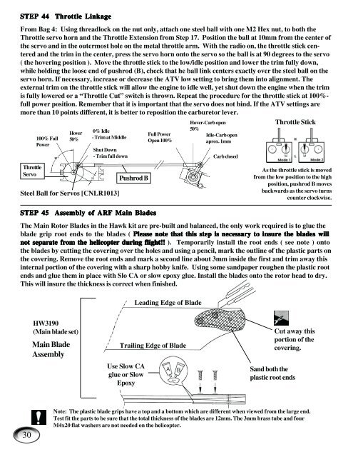
From Bag 4: Using threadlock on the nut only, attach one steel ball with one M2 Hex nut, to both the<br />
Throttle servo horn and the Throttle Extension from Step 17. Position the ball at 10mm from the center of<br />
the servo and in the outermost hole on the metal throttle arm. With the radio on, the throttle stick centered<br />
and the trim in the center, press the servo horn onto the servo so the ball is at 90 degrees to the servo<br />
( the hovering position ). Move the throttle stick to the low/idle position and lower the trim fully down,<br />
while holding the loose end of pushrod (B), check that he ball link centers exactly over the steel ball on the<br />
servo horn. If necessary, increase or decrease the ATV low setting to bring them into alignment. The<br />
external trim on the throttle stick will allow the engine to idle well, yet shut down the engine when the trim<br />
is fully lowered or a “Throttle Cut” switch is thrown. Repeat the procedure for the throttle stick at 100%full<br />
power position. Remember that it is important that the servo does not bind. If the ATV settings are<br />
more than 10 points different, it is better to reposition the carburetor lever.<br />
Hover-Carb open<br />
Throttle Stick<br />
Throttle<br />
Servo<br />
The Main Rotor Blades in the <strong>Hawk</strong> kit are pre-built and balanced, the only work required is to glue the<br />
blade grip root ends to the blades ( Please Please note note that that this this this step step is is necessary necessary to to insure insure the the blades blades will<br />
will<br />
not not separate separate from from from the the the helicopter helicopter helicopter during during during flight!! flight!!<br />
flight!! ). Temporarily install the root ends ( see note ) onto<br />
the blades by cutting the covering over the holes and using a pencil, mark the outline of the plastic parts on<br />
the covering. Remove the root ends and mark a second line about 3mm inside the first and trim away this<br />
internal portion of the covering with a sharp hobby knife. Using some sandpaper roughen the plastic root<br />
ends and glue them in place with Slo CA or slow epoxy glue. Install the blades onto the rotor head to dry.<br />
This will insure the thickness is correct when finished.<br />
30<br />
100% Full<br />
Power<br />
Hover<br />
50%<br />
0% Idle<br />
- Trim at Middle<br />
Shut Down<br />
- Trim full down<br />
Steel Ball for Servos [CNLR1013]<br />
HW3190<br />
(Main blade set)<br />
Pushrod B<br />
STEP STEP 45 45 Assembly Assembly of of of ARF ARF ARF Main Main Blades<br />
Blades<br />
Main Blade<br />
Assembly<br />
Full Power<br />
Open 100%<br />
Trailing Edge of Blade<br />
Use Slow CA<br />
glue or Slow<br />
Epoxy<br />
50%<br />
Leading Edge of Blade<br />
Idle-Carb open<br />
aprox. 1mm<br />
Carb closed<br />
As the throttle stick is moved<br />
from the low position to the high<br />
position, pushrod B moves<br />
backwards as the servo turns<br />
counter clockwise.<br />
Cut away this<br />
portion of the<br />
covering.<br />
Sand both the<br />
plastic root ends<br />
Note: The plastic blade grips have a top and a bottom which are different when viewed from the large end.<br />
Test fit the parts to be sure that the total thickness of the blades are 12mm. The 3mm brass tube and four<br />
M4x20 flat washers are not needed on the helicopter.