Hawk Sport Construction Manual
Hawk Sport Construction Manual
Hawk Sport Construction Manual

Create successful ePaper yourself
Turn your PDF publications into a flip-book with our unique Google optimized e-Paper software.
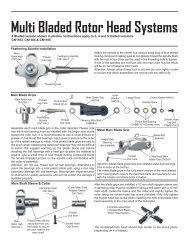
STEP STEP 31 31 Tail Tail Rotor Rotor Rotor Hub<br />
Hub<br />
From parts bag 7: Install the<br />
Tail Rotor Hub onto the tail<br />
rotor output shaft (position<br />
the hub so the hole is aligned<br />
over the indent hole on the<br />
shaft) and secure with one<br />
M3x4 set screw using<br />
threadlock. Insert one M3x10<br />
Socket Cap Screw through<br />
one M3x10 Ball Bearing<br />
(apply the threadlock to the<br />
inside threads of the hub)<br />
and into the tail rotor hub.<br />
Repeat for the other side.<br />
Avoid getting any<br />
threadlock in the bearings.<br />
Tail Rotor Hub<br />
[HW3098]<br />
M3x10 Socket<br />
Cap Screw<br />
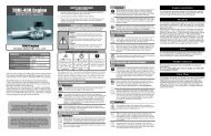
From parts bag 7: Using threadlock on the two M2x10 Phillips Machine Screws and 2mm Nuts, assemble<br />
both Blade Grip Halves over the bearings with the nuts facing to the gearbox, Snap the two balls from the<br />
tail rotor grip into the adjoining pitch slider links. Install the Tail Rotor Blades using two M3x16 Socket<br />
Cap Screws and M3 locknuts. Note the direction of the blades on the diagram, the straight leading edge of<br />
the blade should be on the same side as the ball on the blade grip.<br />
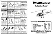
Install the M2 Short<br />
Steel Ball, threaded<br />
from the bottom of the<br />
bellcrank. Install the<br />
tail rotor bellcrank onto<br />
the tail rotor gear box<br />
with one M3x16<br />
Socket Cap Screw,<br />
inserted through the<br />
brass bushing with the<br />
washer side on the<br />
bottom ( make make sure<br />
sure<br />
the the steel steel steel ball ball ball at at the<br />
the<br />
bottom bottom of of the the pitch<br />
pitch<br />
slider slider is is engaged engaged into<br />
into<br />
the the end end of of the the the t/r<br />
t/r<br />
bellcrank bellcrank ) and<br />
thread into the hole on<br />
3x10 Ball<br />
Bearing x 2<br />
[CNBB1030]<br />
STEP STEP 32 32 32 Tail Tail Rotor Rotor Rotor Grips Grips & & & Tail Tail Tail Rotor Rotor Pitch Pitch Lever<br />
Lever<br />
M3x16<br />
Socket Cap<br />
Screw<br />
M2x10 Phillips<br />
Machine Screw x 4<br />
M2 Hex Nut x 4<br />
Leading Edge<br />
M3 Locknut<br />
M3x4 Set Screw<br />
Blade Grip<br />
Halves [HI3096]<br />
Leading Edge<br />
M3x10 Socket Cap<br />
Screw<br />
Tail Rotor Blades<br />
[HI3099] x 2<br />
Steel ball at the bottom of the<br />
pitch slider is engaged into<br />
hole.<br />
M3x16 Socket Cap Screw<br />
the tail rotor gearbox.<br />
Tail Rotor Bellcrank [HI3102A]<br />
M2 Short Steel Ball<br />
[CNLR1013]<br />
After flying the model, if a buzzing vibration is noticed on the ends of the vertical or horizontal fin,<br />
you can remove the complete tail rotor assembly with the hub and further balance it using a High<br />
Point balancer. Careful sanding of the rotor blades is all that would be needed.<br />
21