Hawk Sport Construction Manual
Hawk Sport Construction Manual
Hawk Sport Construction Manual

You also want an ePaper? Increase the reach of your titles
YUMPU automatically turns print PDFs into web optimized ePapers that Google loves.
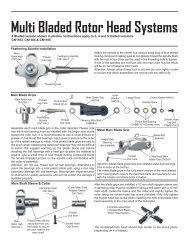
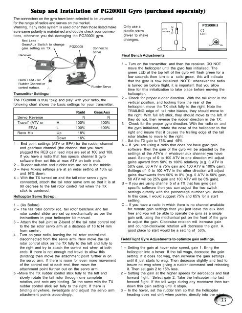
The connectors on the gyro have been selected to be universal<br />
for the range of radios and servos on the market.<br />
Warning, if any radio system is used other than those listed make<br />
sure same polarity is maintained and double check your connections,<br />
otherwise you risk damaging the PG2000II gyro.<br />
Red Lead -<br />
Gear/Aux Switch to change<br />
gain setting on TX.<br />
Receiver<br />
Setup Setup and and Installation Installation of of PG2000II PG2000II Gyro Gyro (purchased (purchased separately)<br />
separately)<br />
Black Lead - Rx<br />
Rudder Channel or<br />
control surface.<br />
Transmitter Settings:<br />
PG2000II<br />
Connect to<br />
Servo<br />
Rudder Servo<br />
The PG2000II is truly “plug and play” with your radio, the<br />
following chart shows the basic settings for your transmitter.<br />
Rudd Gear/Aux<br />
Servo Reverse N N<br />
Travel* (ATV or H 100% 100%<br />
EPA) L 100% 100%<br />
Revo Mix Up 18%<br />
Down 16%<br />
1 – End point settings (ATV or EPA) for the rudder channel<br />
and gear/aux channel (the channel that you have<br />
plugged the RED gain lead into) are set at 100 and 100.<br />
If you have a radio that has special channel 5 gyro<br />
software then set this at max ATV on both ends.<br />
2 – Rudder sub-trim and rudder trim are set in the middle.<br />
3 – Revo Mixing settings are at an initial setting of 18% up<br />
and 16% down.<br />
4 – With the TX turned on and the tail rotor servo / gyro<br />
connected, attach the tail rotor servo arm so that it is at<br />
90 degrees to the tail rotor control rod when the TX<br />
stick is centered.<br />
Helicopter Servo Set-up:<br />
1 – (As Before)<br />
2 – The tail rotor control rod, tail rotor bellcrank and tail<br />
rotor control slider are set up mechanically as per the<br />
instructions in your helicopter kit manual.<br />
3 – Attach the ball joint or Z-bend of the tail rotor control rod<br />
to the tail rotor servo arm at a distance of 10 to14 mm<br />
from center.<br />
4 - Turn on your radio, leaving the tail rotor control rod<br />
disconnected from the servo arm. Now move the tail<br />
rotor control stick on the TX fully to the left and fully to<br />
the right and try to attach the control rod when at both<br />
ends. If there is not enough rod travel to allow this<br />
(binding) then move the attachment point further in on<br />
the servo arm. If there is room for even more movement<br />
of the control rod at each end, then move the<br />
attachment point further out on the servo arm.<br />
5 –Move the TX rudder control stick fully to the left and<br />
slowly rotate the tail rotor through one complete<br />
rotation, and note any binding. Do the same with the TX<br />
rudder control stick set fully to the right. If there is<br />
binding anywhere, investigate and adjust the servo arm<br />
attachment points accordingly.<br />
Only use a<br />
plastic screw<br />
driver to make<br />
changes.<br />
Final Bench Adjustments<br />
1 – Turn on the transmitter, and then the receiver. DO NOT<br />
move the helicopter until the gyro has initialized. The<br />
green LED at the top left of the gyro will flash green for a<br />
few seconds then turn to a solid green, this will indicate<br />
that the gyro is now initialized. NOTE: whenever the radio<br />
is turned on before flight, it is important that you allow<br />
time for this initialization to take place before moving the<br />
helicopter.<br />
2 – Check for proper rudder direction. With the tail rotor in the<br />
vertical position, and looking from the rear of the<br />
helicopter, move the TX stick fully to the right. Note the<br />
TRAILING edge of tail rotor blades, they should move to<br />
the right. With full left stick, they should move to the left. If<br />
they do not, then reverse the rudder direction in the TX.<br />
3 – Check for the proper gyro direction. With the radio on and<br />
the gyro initialized, rotate the nose of the helicopter to the<br />
right and insure that it causes the trailing edge of the tail<br />
rotor blades to move to the right.<br />
4 – Set the TX gain to 75% and 45%<br />
A – If you are using a radio that does not have gyro gain<br />
software, then the gain of the gyro will be adjusted by the<br />
settings of the ATV’s in whatever aux channel you have<br />
used. Settings of 0 to 100 ATV in one direction will adjust<br />
gains upward from 50% to 100% relatively (e.g. 0 ATV is<br />
50% gain, 50 ATV is 75% gain and 100 ATV is 100% gain).<br />
Settings of 0 to 100 ATV in the other direction will adjust<br />
gains downwards from 50% to 0% (e.g. 0 ATV is 50% gain,<br />
50 ATV will be 25% gain and 100 ATV will be 0% gain).<br />
B – If you are using channel 5 of a TX that has gyro gain<br />
specific software then you can adjust the two switch<br />
settings directly with the percentage number you desire.<br />
In this case, I would suggest 75% and 65% for a start<br />
setting.<br />
C – If you have a radio in which there is no channel available<br />
for remote gain settings then you just leave the aux lead<br />
free and you will be able to operate the gyro as a single<br />
gain unit, using the mechanical pot on the front of the gyro<br />
to adjust the gain. Clockwise rotation will increase gain<br />
and counter-clockwise rotation will decrease the gain. A<br />
good place to start would be a setting of 50%.<br />
Field/Flight Gyro Adjustments to optimize gain settings.<br />
1 – Setting the gain at hover rotor speed, gain 1. Bring the<br />
helicopter into a hover. If the tail wags, decrease the gain<br />
setting. If it does not wag, then increase the gain settings<br />
until it just starts to wag. Then decrease slightly and test to<br />
insure no wag when giving a rudder command and releasing<br />
it. Then set gain 2 to 15% less.<br />
2 – Setting the gain at the higher speeds for aerobatics and fast<br />
forward flight. Select gain 2. Take the helicopter into fast<br />
forward flight. If the tail wags during any maneuver then turn<br />
down this gain setting until it stops.<br />
3 – In the hover, set the rudder trim so that the helicopter<br />
heading does not drift when pointed directly into the wind.<br />
33