Hawk Sport Construction Manual
Hawk Sport Construction Manual
Hawk Sport Construction Manual

Create successful ePaper yourself
Turn your PDF publications into a flip-book with our unique Google optimized e-Paper software.
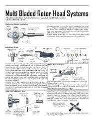
STEP STEP STEP 5 5 Flybar, Flybar, Paddles Paddles & & Flybar Flybar Control Control Arms<br />
Arms<br />
From parts bag 1: Slide and center the Flybar through the seesaw arm assembly. Install one Steel ball (care<br />
must be taken when inserting the M2 Steel Ball, it is best to turn 1/2 in - then 1/2 out (like tapping a hole) until<br />
the ball is fully seated) onto each flybar control arm. Slide the M3x3 Spacer and Flybar Control Arm onto the<br />
flybar. Loosely tighten the control arms with two M4x5 Set Screws. Using a ruler, check the distance between<br />
the end of the flybar and the control arm and adjust until the lengths are the same and there is no free play<br />
between the control arms and the rotor head. Slide the Flybar Weight (Note: the flat end of the weight faces<br />
the paddle) and thread on the Flybar Paddle until all the threads are covered onto the flybar and align the<br />
paddles parallel. Again using the ruler, rotate one paddle or the other to get equal distances, remember the<br />
leading edge of the paddles turn clockwise and finally apply threadlock on the two M3x3 Set Screws to secure<br />
the flybar weights. The last step is to secure the flybar control arms, remove one set screw at a time, apply<br />
threadlock and tighten in place.<br />
Flybar Control Arm x 2<br />
Flybar Paddles<br />
Steel Ball x 2<br />
& Weights<br />
[HI3176]<br />
[HI3179] x 2<br />
M3x3 Set<br />
Screw x 2<br />
M4x5 Set<br />
Screw x 2<br />
Leading Edge<br />
Spacer M3x3<br />
[HI3167D]<br />
A=B=A<br />
A B A<br />
Clockwise<br />
Align each paddle 'A' to be parallel with the flybar Rotation<br />
control arms 'B'. This is made very simple with the optional pitch and paddle gauge CN2026<br />
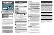
STEP STEP 6 6 Washout Washout Unit Unit & & Swashplate<br />
Swashplate<br />
Attach two Medium Balls to the Washout Mixing<br />
Arms ( Note, Note, attach attach attach from from the the flat flat flat side side of<br />
of<br />
the the arm). arm<br />
arm Secure the semi-assembled mixing<br />
arms onto the Washout Hub using one slide tube<br />
inserted from the flat side and secured using Medium<br />
one 3x16mm Socket Cap Screw and one Black Ball x 2<br />
3x7mm Flat Washer per arm (note, note, use<br />
use [CNLR1015]<br />
the the left left side side hole hole hole on on on the the the hub). hub<br />
hub After<br />
attaching the balls to the swashplate, press<br />
the radius link onto the inner short balls on<br />
the Swashplate.<br />
Medium<br />
Steel Ball x 2<br />
[CNLR1015]<br />
Swashplate Assembly [HI3146B]<br />
Radius Link &<br />
M2x12 Pin<br />
[HI3152A]<br />
Short Steel<br />
Ball x 5<br />
[CNLR1014]<br />
Leading Edge<br />
M3x7 Flat<br />
Washer x 2<br />
Optional Head<br />
Button<br />
CN2215<br />
Note: Secure oilite bushings<br />
to hub with thin CA<br />
Flybar [HW3173]<br />
* packed with<br />
tailboom<br />
For balancing of<br />
rotor head see Final<br />
Adjustments<br />
Washout Hub<br />
Assembly<br />
[HI3152C]<br />
Slide Tube x 2<br />
Oilite<br />
Bushing x 2<br />
M3x16 Socket<br />
Cap Screw x 2<br />
Starting with the inside race, apply threadlock<br />
and attach two short balls (Tip Tip 1 11)<br />
1 directly<br />
across from each other, similarly attach two<br />
medium balls to the remaining holes. Attach<br />
the three short balls (Tip Tip 2 22)<br />
2 to the outside<br />
race. The rear location is not used now.<br />
7