Hawk Sport Construction Manual
Hawk Sport Construction Manual
Hawk Sport Construction Manual

You also want an ePaper? Increase the reach of your titles
YUMPU automatically turns print PDFs into web optimized ePapers that Google loves.
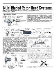
STEP STEP 22 22 22 Final Final Rotor Rotor Head Head Assembly Assembly<br />
Assembly<br />
M3x16<br />
Socket<br />
Cap Screw<br />
&<br />
M3 Locknut<br />
Swashplate &<br />
Washout<br />
Assembly<br />
from Step 6<br />
Short Steel Ball<br />
Completed Rotor<br />
Head Assembly from<br />
Step 5<br />
Main Frame Assembly from Step 21<br />
Speed Torpedo<br />
Muffler CN3040<br />
Long Steel Ball<br />
Muffler<br />
Pressure<br />
tap<br />
Optional CN3055H High Performance<br />
Tuned Pipe available.<br />
Remove the M3x16 Socket Cap Screw from the top of the<br />
main shaft. Slide the swashplate and washout assembly<br />
(from from Step Step 6) 6<br />
6 onto the main shaft and snap the elevator<br />
lever arm onto the single front ball on the swashplate.<br />
Slide the completed rotor head assembly (from from Step Step 5 55)<br />
5<br />
onto the shaft and align the hole in the head block with<br />
the hole in the top of the main shaft. Insert one M3x16<br />
Socket Cap Screw and 3mm locknut (from from Bag Bag 2 22)<br />
2 to<br />
secure the two. (Note: (Note: (Note: Make Make sure sure the the pins pins in in the<br />
the<br />
rotor rotor head head block block are are aligned aligned and and inserted inserted into into the<br />
the<br />
holes holes in in the the washout washout washout unit.) unit.)<br />
unit.) Apply some oil sparingly<br />
to the washout hub assembly to insure they slide<br />
smoothly.<br />
Following assembly, move the collective lever<br />
fore and aft to the endpoints. The swashplate<br />
and washout unit should be very smooth<br />
throughout the movement range. If not, inspect<br />
the fit of the washout guide to the pins in<br />
the rotor head, these pins can be bent slightly if<br />
binding. Also check the collective axle, the<br />
screws here may be too tight. The fit of the ball<br />
links sometimes can cause binding, with time<br />
these will break in. These few points are the<br />
most common which will cause servo strain<br />
leading to premature wear and can make the<br />
collective control a little vague.<br />
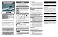
STEP STEP 23 23 Attaching Attaching the the Muffler<br />
Muffler<br />
Attach the muffler to the engine with the screws<br />
provided with the muffler (Tip Tip 1 11-<br />
1 using hi-temp<br />
threadlock). Attach the pressure tap to the top of<br />
the muffler and the M4x6 Phillips Machine screw<br />
to the bottom hole in the muffler, remember to use<br />
hi-temp RTV sealer or threadlock on these parts.<br />
For a good seal between the muffler and the<br />
exhaust port, use a gasket made from thin<br />
aluminum, brass or exhaust gasket material. To<br />
properly seal the fit, after running the engine for<br />
several minutes on the first run, shut down the<br />
engine and re-tighten the bolts, while the engine<br />
is still hot. The extra 1/8 to1/4 turn on the bolts<br />
will seat the muffler in place.<br />
17