Hawk Sport Construction Manual
Hawk Sport Construction Manual
Hawk Sport Construction Manual

Create successful ePaper yourself
Turn your PDF publications into a flip-book with our unique Google optimized e-Paper software.
-2<br />
Pitch Curve<br />
Hovering - ( linear ) Normal Flight Mode<br />
Low Mid High<br />
Stick Position<br />
Aerobatic Flying - Flight Mode 1<br />
Low Mid High<br />
Stick Position<br />
3D Flying - Flight Mode 2<br />
Autorotation - Throttle Hold<br />
9<br />
5<br />
-5<br />
9<br />
-5<br />
-9<br />
Low Mid High<br />
Stick Position<br />
-5<br />
Low Mid High<br />
Stick Position<br />
9<br />
0<br />
12<br />
5<br />
Pitch Range<br />
Pitch Range<br />
Pitch<br />
Range<br />
Pitch<br />
Range<br />
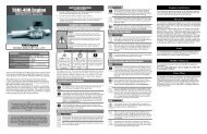
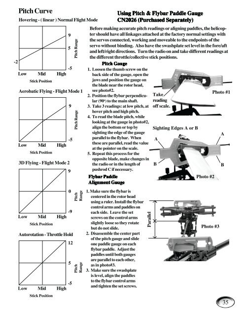
Before making accurate pitch readings or aligning paddles, the helicopter<br />
should have all linkages attached at the factory normal settings with<br />
the servos connected, working and moveable to the endpoints of the<br />
servo without binding. Also have the swashplate set level in the fore/aft<br />
and left/right directions. Turn the radio on and take different readings at<br />
the different throttle/collective stick positions.<br />
Pitch Pitch Pitch Gauge<br />
Gauge<br />
1. Loosen the thumb screw on the<br />
back side of the gauge, open the<br />
jaws and position the gauge on<br />
the blade near the rotor head,<br />
see photo#2.<br />
2. Position the flybar perpendicular<br />
(90 o ) to the main shaft.<br />
3. Take 3 readings: at low pitch, at<br />
hover pitch and high pitch.<br />
4. To read the blade pitch, while<br />
looking at the gauge in photo#2,<br />
align the bottom or top by<br />
sighting the edge of the gauge<br />
parallel to the flybar. When<br />
these are parallel, read the value<br />
at the pointer on the scale.<br />
5. Repeat this process for the<br />
opposite blade, make changes in<br />
the radio or in the length of<br />
pushrod C if necessary.<br />
Flybar Flybar Paddle<br />
Paddle<br />
Alignment Alignment Alignment Gauge<br />
Gauge<br />
1. Make sure the flybar is<br />
centered in the rotor head<br />
using a ruler. Install the flybar<br />
control arms and paddles on<br />
each side. Leave the set<br />
screws on the control arms<br />
slightly loose so they rotate<br />
but do not slide.<br />
2. Disassemble the center part<br />
of the pitch gauge and slide<br />
one paddle gauge on each<br />
flybar paddle. Adjust the<br />
paddles until both gauges<br />
are parallel to each other,<br />
as in photo#3.<br />
3. Make sure the swashplate<br />
is level, align the paddles<br />
to the flybar control arms<br />
and tighten the set screws.<br />
Using Using Pitch Pitch & & Flybar Flybar Paddle Paddle Gauge<br />
Gauge<br />
CN2026 CN2026 CN2026 (Purchased (Purchased Separately)<br />
Separately)<br />
Parallel<br />
Take<br />
reading<br />
off scale.<br />
Sighting Edges A or B<br />
A<br />
B B<br />
Photo #2<br />
Photo #3<br />
Photo #1<br />
A<br />
35