brinkmann - Ramirent
brinkmann - Ramirent
brinkmann - Ramirent

You also want an ePaper? Increase the reach of your titles
YUMPU automatically turns print PDFs into web optimized ePapers that Google loves.
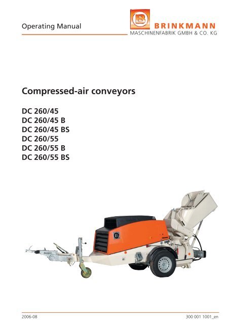
Operating Manual<br />
Compressed-air conveyors<br />
DC 260/45<br />
DC 260/45 B<br />
DC 260/45 BS<br />
DC 260/55<br />
DC 260/55 B<br />
DC 260/55 BS<br />
BRINKMANN<br />
MASCHINENFABRIK GMBH & CO. KG<br />
2006-08 300 001 1001_en
BRINKMANN • Maschinenfabrik GmbH & Co. KG<br />
An der Heller 4-12 · D 33758 Schloß Holte<br />
Telefon 0 52 07 / 91 47 - 0 · Telefax 0 52 07 / 91 47 10<br />
E-Mail: <strong>brinkmann</strong>@estrichboy.de · Internet: www.estrichboy.de
Table of contents<br />
BRINKMANN<br />
MASCHINENFABRIK GMBH & CO. KG<br />
1 Introduction<br />
Machine data ..................................................................1 - 1<br />
1.1 Foreword ........................................................................1 - 2<br />
1.2 Signs and symbols ...........................................................1 - 3<br />
2 Safety Regulations<br />
2.1 Principle ..........................................................................2 - 2<br />
Onwards sale ..............................................................2 - 2<br />
2.2 Designated use ...............................................................2 - 3<br />
2.3 Use contrary to the designated use .................................2 - 4<br />
Liability .......................................................................2 - 4<br />
Exclusion of liability .....................................................2 - 4<br />
Modifi cations ..............................................................2 - 4<br />
2.4 Sources of danger ...........................................................2 - 5<br />
Malfunctions ...............................................................2 - 5<br />
Hot machine components ...........................................2 - 5<br />
Delivery hoses and hose couplings ..............................2 - 5<br />
Discharge stand ..........................................................2 - 5<br />
Mixing tank ................................................................2 - 5<br />
Loader ........................................................................2 - 5<br />
2.5 Safety equipment ............................................................2 - 6<br />
2.6 Safety information for pressure reservoirs ........................2 - 6<br />
2.7 Operating pressure reservoirs ..........................................2 - 7<br />
2.8 Personnel selection and qualifi cation ...............................2 - 7<br />
Training ......................................................................2 - 7<br />
Qualifi ed electrician ....................................................2 - 8<br />
Hydraulics engineer .....................................................2 - 8<br />
2.9 Workplace ......................................................................2 - 8<br />
Operator .....................................................................2 - 8<br />
Screed layer ................................................................2 - 8<br />
2.10 Working range ................................................................2 - 8<br />
2.11 Procedure in an emergency .............................................2 - 8<br />
2.12 Protective equipment ......................................................2 - 9<br />
2.13 Injury risks .......................................................................2 - 10<br />
00DF001_0608_en I
Table of contents<br />
BRINKMANN<br />
MASCHINENFABRIK GMBH & CO. KG<br />
2.14 Blockages ........................................................................2 - 11<br />
2.15 Hydraulic and pneumatic systems ....................................2 - 12<br />
2.16 Noise ..............................................................................2 - 13<br />
2.17 Environmental protection ................................................2 - 13<br />
2.18 Spare parts ......................................................................2 - 13<br />
2.19 Storing the machine ........................................................2 - 13<br />
2.20 Unauthorised/Inadvertent machine start-up .....................2 - 14<br />
3 Technical description<br />
3.1 Description ......................................................................3 - 1<br />
3.2 Equipment ......................................................................3 - 1<br />
3.3 Scope of supply ...............................................................3 - 1<br />
3.4 Overview .........................................................................3 - 2<br />
3.5 Technical data .................................................................3 - 3<br />
Compressor/Engine .....................................................3 - 4<br />
Output ........................................................................3 - 4<br />
Noise level ..................................................................3 - 4<br />
Rating plate ................................................................3 - 5<br />
3.6 Options ...........................................................................3 - 5<br />
3.7 Safety equipment ............................................................3 - 6<br />
EMERGENCY STOP button ..........................................3 - 6<br />
Protective grille ...........................................................3 - 7<br />
Guard .........................................................................3 - 8<br />
Maintenance fl ap ........................................................3 - 8<br />
3.8 Function description ........................................................3 - 9<br />
General ......................................................................3 - 9<br />
Unit description ..........................................................3 - 10<br />
Compressor ................................................................3 - 10<br />
Mixing tank ................................................................3 - 11<br />
Automatic central lubrication system ...........................3 - 12<br />
Automatic pressure cut-out .........................................3 - 12<br />
Operating elements ....................................................3 - 13<br />
Loader ........................................................................3 - 14<br />
Scraper .......................................................................3 - 14<br />
Radio remote control for the scraper ...........................3 - 15<br />
Working light with magnet foot ..................................3 - 15<br />
Automatic mixing tank cleaner ....................................3 - 16<br />
II 00DF001_0608_en
Table of contents<br />
BRINKMANN<br />
MASCHINENFABRIK GMBH & CO. KG<br />
4 Transport, installation and connection<br />
4.1 Loading ...........................................................................4 - 1<br />
4.2 Chassis ............................................................................4 - 2<br />
Breakaway cable .........................................................4 - 3<br />
Tailgate bracket ...........................................................4 - 4<br />
Support wheel ............................................................4 - 5<br />
Handbrake ..................................................................4 - 6<br />
Wheel chocks .............................................................4 - 6<br />
Setting the parallel adjuster .........................................4 - 7<br />
Ball head coupling ......................................................4 - 8<br />
Permitted slewing circle ..............................................4 - 9<br />
Permitted drawbar load ..............................................4 - 9<br />
Connecting the machine .............................................4 - 10<br />
Disconnecting the machine .........................................4 - 11<br />
4.3 Transportation and driving ...............................................4 - 12<br />
4.4 Before driving off ............................................................4 - 13<br />
4.5 Set-up site .......................................................................4 - 14<br />
Set-up site requirements .............................................4 - 14<br />
Location ......................................................................4 - 14<br />
Setting up ...................................................................4 - 15<br />
Angle of inclination .....................................................4 - 15<br />
Alignment ...................................................................4 - 16<br />
4.6 Laying the delivery line ....................................................4 - 16<br />
Selecting the delivery hoses .........................................4 - 17<br />
Selecting the hose couplings .......................................4 - 17<br />
Selecting the connector for the<br />
mixing tank outlet .......................................................4 - 18<br />
Laying the delivery hoses .............................................4 - 18<br />
Connecting the discharge stand ..................................4 - 19<br />
4.7 Start-up ..........................................................................4 - 20<br />
Preparing for start-up ..................................................4 - 20<br />
Checking oil levels ......................................................4 - 21<br />
Checking the air fi lter .................................................4 - 21<br />
Inspecting the mixing paddles .....................................4 - 22<br />
Inspecting the wear plates ..........................................4 - 22<br />
Inspecting the mixing shaft bearing .............................4 - 22<br />
00DF001_0608_en III
Table of contents<br />
BRINKMANN<br />
MASCHINENFABRIK GMBH & CO. KG<br />
Refuelling the machine ...............................................4 - 23<br />
Test run .......................................................................4 - 24<br />
Function checks ..........................................................4 - 24<br />
Shutting down the machine after operation ................4 - 26<br />
4.8 Notes on winter operation ..............................................4 - 26<br />
5 Operation<br />
5.1 Shutting down in an emergency ......................................5 - 1<br />
5.2 Safety .............................................................................5 - 2<br />
Safety measures during normal operation ...................5 - 3<br />
Checks before starting ................................................5 - 3<br />
Interruptions in work ..................................................5 - 3<br />
Binder in your eyes ......................................................5 - 3<br />
5.3 Control panel on the machine .........................................5 - 4<br />
Digital control panel ....................................................5 - 4<br />
Analogue control panel ...............................................5 - 4<br />
Control panel buttons .................................................5 - 5<br />
Indicator lamps on the control panel ...........................5 - 5<br />
Covered buttons - digital control .................................5 - 6<br />
Special functions - digital control ................................5 - 7<br />
Fault display - digital control .......................................5 - 7<br />
5.4 Starting the machine .......................................................5 - 9<br />
Main switch ................................................................5 - 9<br />
Starting the diesel engine ............................................5 - 10<br />
Switching off the diesel engine ...................................5 - 10<br />
5.5 Operating the loader .......................................................5 - 11<br />
5.6 Operating the scraper .....................................................5 - 12<br />
Cable operation ..........................................................5 - 13<br />
Charging the battery ...................................................5 - 13<br />
5.7 Closing the cover on the mixing tank ..............................5 - 14<br />
5.8 Opening the cover on the mixing tank ............................5 - 15<br />
5.9 Manual depressurisation .................................................5 - 15<br />
5.10 Loading the mixing tank ..................................................5 - 16<br />
IV 00DF001_0608_en
Table of contents<br />
BRINKMANN<br />
MASCHINENFABRIK GMBH & CO. KG<br />
5.11 Delivering material / Generating tank pressure .................5 - 17<br />
Mixing mechanism button ..........................................5 - 17<br />
Flotation air button .....................................................5 - 17<br />
5.12 Adjusting the header and fl otation air .............................5 - 18<br />
Delivery types / Maximum delivery pressure .................5 - 19<br />
Adjusting the air valves in line with<br />
the delivery type .........................................................5 - 19<br />
5.13 Adjusting the ventilation pressure ....................................5 - 19<br />
5.14 Detaching hose couplings after a delivery cycle ...............5 - 20<br />
5.15 Delivery stops / Blockages ................................................5 - 21<br />
Locating and eliminating blockages .............................5 - 21<br />
Stubborn blockages ....................................................5 - 22<br />
Most frequent causes of blockages .............................5 - 23<br />
5.16 Stopping material delivery ...............................................5 - 24<br />
5.17 Finishing work .................................................................5 - 24<br />
5.18 Cleaning .........................................................................5 - 25<br />
General .......................................................................5 - 25<br />
Cleaning the mixing tank ............................................5 - 26<br />
Automatic mixing tank cleaner (optional) ....................5 - 27<br />
High-pressure cleaner (optional) ..................................5 - 28<br />
Cleaning the delivery hoses .........................................5 - 29<br />
Cleaning the header and fl otation air hoses ................5 - 30<br />
5.19 Connection for air tapping ..............................................5 - 31<br />
5.20 Shutting down the machine for long periods ...................5 - 32<br />
5.21 Final machine decommissioning ......................................5 - 33<br />
6 Troubleshooting guide<br />
DC 260 General ..............................................................6 - 1<br />
6.1 Machine general .............................................................6 - 1<br />
6.2 Troubleshooting at the chassis .........................................6 - 2<br />
00DF001_0608_en V
Table of contents<br />
BRINKMANN<br />
MASCHINENFABRIK GMBH & CO. KG<br />
7 Maintenance<br />
7.1 Safety instructions ...........................................................7 - 1<br />
7.2 Maintenance intervals .....................................................7 - 3<br />
Set screw tightening torques ...........................................7 - 11<br />
7.3 Welding work .................................................................7 - 12<br />
7.4 Tightening torques ..........................................................7 - 12<br />
7.5 Operating materials .........................................................7 - 13<br />
7.6 Shutting down the machine ............................................7 - 15<br />
7.7 Maintenance kits .............................................................7 - 16<br />
Maintenance cards<br />
01-001 Visual inspection .................................................7 - 17<br />
02-001 Lubrication diagrams ...........................................7 - 19<br />
03-001 Central lubrication system ...................................7 - 23<br />
04-001 Battery ................................................................7 - 25<br />
05-001 Air fi lter ..............................................................7 - 29<br />
06-001 Fuel fi lter ............................................................7 - 33<br />
07-001 Oil cooler ............................................................7 - 35<br />
08-001 Engine ................................................................7 - 37<br />
09-001 Compressor ........................................................7 - 43<br />
10-001 Hydraulic system .................................................7 - 49<br />
11-001 Check valves .......................................................7 - 53<br />
12-001 Tank outlet ..........................................................7 - 55<br />
13-001 Hoses ..................................................................7 - 57<br />
8 Conformity<br />
Declaration of conformity ................................................8 - 1<br />
Fax order form<br />
VI 00DF001_0608_en
1 Introduction<br />
1 Introduction<br />
BRINKMANN<br />
MASCHINENFABRIK GMBH & CO. KG<br />
This chapter contains instructions and information to help you use this<br />
operating manual. If you have any queries, please contact:<br />
Brinkmann Maschinenbau GmbH & Co. KG<br />
An der Heller 4-12<br />
D-33758 Schloß Holte, Germany<br />
Tel: +49 (0) 52 07 / 91 47-0<br />
Fax: +49 (0) 52 07 / 91 47-10<br />
Internet: www.estrichboy.de<br />
E-mail: info@estrichboy.de<br />
or your local branch or works agency.<br />
Machine data Before operating the machine, please enter the following data from the<br />
rating plate here:<br />
1) Machine model:<br />
2) Vehicle ID no.:<br />
3) Year of manufacture:<br />
1)<br />
3) 2)<br />
01DF001_0607_en 1 - 1
1 Introduction<br />
BRINKMANN<br />
MASCHINENFABRIK GMBH & CO. KG<br />
1.1 Foreword This operating manual is designed to familiarise the user with the<br />
machine and assist him in using the machine properly in all possible<br />
applications.<br />
The operating manual contains important information on how to<br />
operate the machine safely, properly and economically. Observing<br />
these instructions helps to avoid danger, to reduce repair costs and<br />
downtimes, and to increase the reliability and service life of the<br />
machine.<br />
The operating manual must be supplemented by the relevant national<br />
rules and regulations for accident prevention and environmental<br />
protection.<br />
Always keep the operating manual with the machine.<br />
The machine owner must make the location of this operating manual<br />
known to all personnel charged with performing jobs on the machine<br />
and ensure it is accessible at all times. This operating manual must be<br />
read and applied by any person who carries out work with or on the<br />
machine, e.g.<br />
− Operation, including set-up, fault rectifi cation in the course of work,<br />
removal of production waste, maintenance and disposal of fuels and<br />
consumables,<br />
− Service (maintenance, inspection, repair) and/or<br />
− Transportation.<br />
Generally recognised rules of technology for safe and proper working<br />
must be observed in addition to the operating manual and mandatory<br />
rules and regulations for accident prevention and environmental<br />
protection in the country and place of use of the machine.<br />
You will make it much easier for us to answer any questions or respond<br />
to orders if you can give us the details of the machine model and<br />
the machine number (vehicle ID no.). Send your questions to your<br />
local Brinkmann customer service partner or directly to Brinkmann<br />
Maschinenfabrik GmbH & Co. KG.<br />
Modifi cations are made from time to time in the interests of constant<br />
improvement and may not have been taken into consideration when<br />
this operating manual was printed.<br />
The contents of this document may not be reproduced, in part or in full,<br />
without our written permission. All technical data, drawings etc. are<br />
protected by copyright law.<br />
© Copyright by BRINKMANN MASCHINENFABRIK GmbH & Co. KG<br />
1 - 2 01DF001_0607_en
1 Introduction<br />
1.2 Signs and symbols<br />
�<br />
�<br />
BRINKMANN<br />
MASCHINENFABRIK GMBH & CO. KG<br />
The following signs and symbols are used in these operating<br />
instructions:<br />
Action symbols<br />
Text following this symbol describes tasks that you are required to work<br />
through, generally in the sequence shown from top to bottom.<br />
Text after this icon describes the result or the effect of an action.<br />
Reference to maintenance cards<br />
This symbol is used to refer to required maintenance cards, possibly as a<br />
supplement to the maintenance cards you are currently reading.<br />
The following special tools are required<br />
This icon identifi es the special tools required to carry out the work.<br />
Normal tools, i.e. standard tools or tools carried in the vehicle are not<br />
listed additionally.<br />
Environmental protection ––––––––––––––––––––––––––––––––––––<br />
This symbol is used to identify tasks where particular attention must be<br />
paid to environmental protection. Accompanying text appears in italics<br />
and is underlined.<br />
Note ––––––––––––––––––––––––––––––––––––––––––––––––––––––––<br />
Important specifi cations regarding economical use of the machine are<br />
highlighted with the word "Note" in bold and the pictogram illustrated.<br />
Accompanying text appears in italics and is underlined.<br />
Caution –––––––––––––––––––––––––––––––––––––––––––––––––––––<br />
Particular specifi cations or instructions and prohibitions relating to<br />
damage prevention are highlighted with the word "Caution" in bold<br />
and the pictogram illustrated. Accompanying text appears in italics and<br />
is underlined.<br />
Continued on next page<br />
01DF001_0607_en 1 - 3
1 Introduction<br />
BRINKMANN<br />
MASCHINENFABRIK GMBH & CO. KG<br />
Danger ––––––––––––––––––––––––––––––––––––––––––––––––––––––<br />
Particular specifi cations or instructions and prohibitions relating to<br />
the prevention of personal injury or extensive damage are highlighted<br />
with the word "Danger" in bold, the pictogram illustrated and a line.<br />
Accompanying text appears in italics and is underlined.<br />
If the nature of the danger is known, the text is preceded by the<br />
corresponding warning pictogram.<br />
Danger of crushing–––––––––––––––––––––––––––––––––––––––––––<br />
This symbol is used for tasks that pose a risk of crushing to personnel or<br />
body parts.<br />
Suspended loads –––––––––––––––––––––––––––––––––––––––––––––<br />
This pictogram is used for tasks where falling loads pose a serious risk.<br />
High voltage ––––––––––––––––––––––––––––––––––––––––––––––––<br />
This symbol is used for tasks that pose a risk of electric shock with<br />
potential fatal consequences.<br />
1 - 4 01DF001_0607_en
2 Safety regulations<br />
2 Safety regulations<br />
BRINKMANN<br />
MASCHINENFABRIK GMBH & CO. KG<br />
This chapter summarises the most important safety regulations and<br />
is therefore particularly suitable for instructing new operators for the<br />
fi rst time. Naturally, the various regulations also appear again at the<br />
appropriate points in the operating manual.<br />
Note –––––––––––––––––––––––––––––––––––––––––––––––––––––––<br />
Special safety regulations may be necessary for some tasks. These<br />
special safety regulations are only found in the description of the<br />
particular task. The following is a list of regulations and safety standards<br />
for further reference:<br />
- Machinery Directive 98/37/EC<br />
- pr EN 12001, Delivery, spraying and distributing machines for concrete<br />
and mortar<br />
- EN 292, Safety of machinery,<br />
- pr EN 12151,<br />
- EN 60204–1, Electrical equipment of machines,<br />
- EN 50081–1,<br />
- EN 50082–1,<br />
- EMC Directives, 89/336/EEC<br />
- Low-voltage Directives, 73/ 23/EEC<br />
- Safety regulations for mortar delivery and spraying machines issued<br />
by the German Industrial Employers' Liability Insurance Association<br />
ZH 1/575.<br />
02DF001_0605_de 2 - 1
2 Safety regulations<br />
BRINKMANN<br />
MASCHINENFABRIK GMBH & CO. KG<br />
2.1 Principle Use the machine only as specifi ed and when in technically perfect<br />
condition; be aware of safety factors and dangers and observe the<br />
operating manual. Any faults, especially those affecting machine safety<br />
should be rectifi ed immediately.<br />
Onwards sale<br />
Make sure that<br />
− safety equipment is not removed, rendered inoperable or modifi ed<br />
(protective grille on the fi lling dome, etc.),<br />
− safety equipment removed for the purposes of maintenance work is<br />
refi tted immediately after the work is completed.<br />
Check operational safety every time you start work. Any defects<br />
identifi ed or suspected must be repaired immediately. If necessary,<br />
inform the supervisor. Stop work if you fi nd any defects that may<br />
jeopardise operational safety.<br />
Danger ––––––––––––––––––––––––––––––––––––––––––––––––––––––<br />
Operate the machine only when all safety equipment is present and<br />
functioning correctly. There is a risk of serious injury.<br />
Use only delivery lines, hoses, couplings etc. that are suitable for the<br />
delivery job, provided by the machine manufacturer and in perfect<br />
condition. Delivery lines are subject to wear which varies according to<br />
the pressure and composition of the medium, the material from which<br />
the delivery line is made, etc.<br />
Observe the following when selling the machine:<br />
Pass all the accompanying documentation (operating manual,<br />
maintenance instructions, diagrams, machine charts, inspection<br />
certifi cates, etc.) you received with your machine on to the new<br />
operator. If necessary, you may have to order the documents from<br />
us, quoting the machine number. The machine should never be sold<br />
without the accompanying documentation.<br />
Report an onwards sale or acquisition to Brinkmann to receive<br />
information relating to modifi cations or innovations relevant to safety<br />
and qualify for technical consultancy from our works.<br />
Instruct the new operator and his operating personnel in the operation<br />
of the machine, just as you were instructed by us, and have them<br />
confi rm that they have received instruction from you. Should you so<br />
require, we will be happy to instruct the new operator and the new<br />
operating personnel on your behalf.<br />
2 - 2 02DF001_0605_de
2 Safety regulations<br />
2.2 Designated use<br />
BRINKMANN<br />
MASCHINENFABRIK GMBH & CO. KG<br />
The machine has been built using state-of-the-art technology and in<br />
accordance with recognised safety regulations. Nevertheless, its use may<br />
constitute a serious or fatal risk to the operator or third parties, or cause<br />
damage to the machine and other property.<br />
You must also observe the operating manual and comply with the<br />
conditions and intervals for maintenance and inspection to operate the<br />
machine within the limits of its designated use.<br />
The machine is designed for mixing and delivering screed, mortar<br />
and concrete mixes with a maximum grain size of 16 mm. Other<br />
materials should only be processed after consultation with Brinkmann<br />
Maschinenfabrik GmbH & Co. KG.<br />
The machine must be inspected for operational reliability by a technical<br />
expert once a year (in accordance with BetrSichV §10 of 27.09.2002).<br />
The operator is responsible for commissioning the inspection.<br />
The maximum permissible gross weight must not be exceeded.<br />
The defi nition specifi ed outlines the designated use of the machine.<br />
The machine generates compressed air for industrial use.<br />
It compresses atmospheric air to operating overpressure and supplies a<br />
defi ned quantity of this air at this pressure.<br />
Using this machine for other tasks, conveying suction media other than<br />
air, operating the compressed air in non-industrial applications and<br />
increasing or reducing operating data such as pressure range, speed,<br />
temperature, etc. outside of the factory settings constitutes improper<br />
use.<br />
All protective devices must be installed and in perfect working order<br />
during operation. Never operate the machine without the safety devices<br />
installed.<br />
Specifi ed inspection work should be carried out.<br />
Never make any modifi cations or conversions to the machine without<br />
fi rst obtaining the manufacturer's permission.<br />
Any work on the machine's electric or hydraulic circuits should be<br />
carried out only by qualifi ed hydraulic and electrotechnical specialists<br />
that have trained to work on the machine.<br />
02DF001_0605_de 2 - 3
2 Safety regulations<br />
2.3 Use contrary to the<br />
designated use<br />
Liability<br />
Exclusion of liability<br />
Modifi cations<br />
BRINKMANN<br />
MASCHINENFABRIK GMBH & CO. KG<br />
Use of the machine other than that described above, or which goes<br />
beyond such use, is considered contrary to the designated use.<br />
Brinkmann Maschinenfabrik GmbH accepts no liability for damage<br />
resulting from such use. The machine operator bears full responsibility.<br />
The operator is obliged to act in accordance with the operating manual.<br />
The safety and accident prevention regulations issued by the following<br />
institutions must be observed:<br />
− Industrial Employers' Liability Insurance Association<br />
− Commercial liability insurance company responsible<br />
− National legal authorities<br />
The following persons are liable by law for accidents resulting from<br />
the failure to comply with safety regulations and accident prevention<br />
regulations or the inadequate supervision of operating personnel:<br />
− the operating personnel, or if deemed not responsible due to lack of<br />
training or basic knowledge in handling the machine,<br />
− his supervisors,<br />
Therefore always make sure that the necessary care is taken.<br />
We state here expressly that Brinkmann Maschinenfabrik accepts no<br />
liability for damage arising from incorrect or negligent operation,<br />
servicing or maintenance or as a result of use contrary to the designated<br />
use. This statement also applies to machine modifi cations, additions and<br />
conversions that may compromise safety. The guarantee will no longer<br />
be valid in such cases.<br />
Never make any modifi cations, additions or conversions to the machine<br />
which may affect safety without fi rst obtaining permission from the<br />
manufacturer. This also applies to the installation and adjustment of<br />
safety equipment and valves as well as to welding work on load-bearing<br />
elements and pressure reservoirs.<br />
In particular, this includes:<br />
− adjustment of safety and control pressures, power outputs, speeds<br />
of rotation and other settings to values other than those set in the<br />
works.<br />
− deactivation or modifi cation of safety equipment. Operating the<br />
machine with faulty safety equipment.<br />
Caution –––––––––––––––––––––––––––––––––––––––––––––––––––––<br />
Safety equipment should be repaired, adjusted or replaced by technically<br />
qualifi ed experts only. All safety-relevant devices must be in place and<br />
fully functional.<br />
2 - 4 02DF001_0605_de
2 Safety regulations<br />
2.4 Sources of danger<br />
Malfunctions<br />
Hot machine<br />
components<br />
Delivery hoses and<br />
hose couplings<br />
Discharge stand<br />
Mixing tank<br />
Loader<br />
BRINKMANN<br />
MASCHINENFABRIK GMBH & CO. KG<br />
During work, never reach into the moving parts of the machine,<br />
whether the machine is running or switched off. Always stop and secure<br />
the machine prior to maintenance work, as described in Chapter 7.6<br />
Shutting down the machine.<br />
Always place chocks under the wheels and apply the handbrake to<br />
prevent the machine from rolling at the set-up site.<br />
Before starting up the machine, make sure that nobody is placed at risk<br />
by the running machine.<br />
Do not loosen or tighten threaded unions on hoses or delivery lines<br />
when these are pressurised.<br />
In the event of malfunctions, stop and secure the machine as described<br />
in Chapter 7.6 Shutting down the machine.<br />
Have any faults rectifi ed immediately.<br />
There is a risk of burns from hot machine components during and after<br />
machine operation (mainly on the engine, compressor, oil systems,<br />
including oil cooler and oil storage tank).<br />
The delivery hoses and hose couplings are designed for a maximum<br />
pressure of 10 bar. The maximum pressure of 10 bar must not be<br />
exceeded.<br />
Material discharged from split delivery hoses or cracked hose couplings<br />
can cause serious injuries, in particular to the eyes.<br />
Never release the hose couplings while the mixing tank is pressurised.<br />
Even if the tank is depressurised, the delivery hoses may still be<br />
pressurised. Always proceed as described in Chapter 5.14 Releasing<br />
hose couplings after a delivery cycle, or in the event of blockages, as<br />
described in Chapter 5.15 Material not delivered / Blockages.<br />
The machine must not be operated without a discharge stand attached<br />
correctly at the delivery hose end.<br />
The end of the hose will thrash around, posing a risk of fatal injury.<br />
The mixing tank must be depressurised before the cover is opened.<br />
Inspect the ventilation lever and tank pressure gauge to see whether the<br />
mixing tank is actually depressurised.<br />
Check the mixing tank at the intervals specifi ed in accordance with<br />
Chapter 2.7 Operating pressure reservoirs.<br />
The operator must make sure that other personnel are not standing<br />
within the slewing circle of the loader during operation.<br />
02DF001_0605_de 2 - 5
2 Safety regulations<br />
2.5 Safety equipment<br />
2.6 Safety information<br />
for the pressure<br />
reservoir<br />
BRINKMANN<br />
MASCHINENFABRIK GMBH & CO. KG<br />
Never remove or modify safety devices on the machine.<br />
Safety devices that are removed for maintenance work, machine setup<br />
or repair must be refi tted directly after the work is complete and<br />
checked to make sure they are fully functional.<br />
Safety devices may only be checked, repaired or replaced by qualifi ed<br />
personnel.<br />
All signs that have a safety or accident prevention function must be<br />
attached to the machine. These signs must not be modifi ed, removed or<br />
damaged. Illegible signs must be replaced.<br />
Pressure reservoirs are subject to pressure reservoir regulations.<br />
§8, Group IV for this particular reservoir.<br />
Brinkmann Maschinenfabrik GmbH & Co. KG has already performed a<br />
pressure and product acceptance test. Regular checks are also necessary<br />
after initial operation. Before making any checks, you must possess<br />
a type approval and pressure test certifi cate. These are provided by<br />
Brinkmann Maschinenfabrik GmbH & Co. KG when the machine is<br />
delivered.<br />
Danger ––––––––––––––––––––––––––––––––––––––––––––––––––––––<br />
Welding work on pressure reservoirs or reservoir outlets is not<br />
permitted. Do not make any structural modifi cations.<br />
2 - 6 02DF001_0605_de
2 Safety regulations<br />
2.7 Operating pressure<br />
reservoirs<br />
2.8 Personnel selection<br />
and qualifi cation<br />
Training<br />
BRINKMANN<br />
MASCHINENFABRIK GMBH & CO. KG<br />
The pressure reservoir operator is responsible for carrying out repeat<br />
checks at the intervals specifi ed and documenting these checks.<br />
Checks must be carried out in Germany by a technical expert (pressure<br />
reservoir regulations § 32)<br />
e.g. at an approved TÜV or DEKRA centre.<br />
Your Trans Mix is subject to the following inspection intervals in<br />
accordance with pressure reservoir regulations § 10:<br />
Internal<br />
inspection<br />
Every<br />
5 years<br />
Pressure test Every<br />
10 years<br />
Specialist inspection inside the reservoir<br />
performed at a certifi ed testing<br />
centre.<br />
Pressure test on tank by an authorised<br />
inspector at a cetifi ed testing<br />
centre.<br />
Note ––––––––––––––––––––––––––––––––––––––––––––––––––––––––<br />
The operator is responsible for keeping reservoir documents safe.<br />
The machine may only be operated, maintained or serviced<br />
independently by persons (machine operators) who<br />
− have reached the legally required age;<br />
− are physically able (rested and not under the infl uence of alcohol,<br />
drugs or medication),<br />
− have been instructed in the operation and maintenance of the<br />
machine,<br />
− can be expected reliably to execute the tasks they are charged with.<br />
The machine may be operated, serviced or maintained only by persons<br />
who are trained to carry out such tasks and have been commissioned to<br />
do so. Areas of responsibility must be clearly defi ned.<br />
Do not allow persons who have not yet completed training or<br />
instruction, or persons taking a general training course, to operate the<br />
machine unless under the constant supervision of a person experienced<br />
in operating the machine.<br />
Couplings should be fi tted only by persons possessing the necessary<br />
experience and equipment required for this task.<br />
Continued on next page<br />
02DF001_0605_de 2 - 7
2 Safety regulations<br />
Qualifi ed electrician<br />
Hydraulics engineer<br />
2.9 Workplace<br />
Operator<br />
Floor layer<br />
2.10 Working area<br />
2.11 Procedure in an<br />
emergency<br />
BRINKMANN<br />
MASCHINENFABRIK GMBH & CO. KG<br />
Work on the electrical system and equipment of the machine should be<br />
carried out by a qualifi ed electrician or by instructed persons under the<br />
supervision and guidance of a qualifi ed electrician and in accordance<br />
with the electrical engineering rules and regulations.<br />
Only personnel having special knowledge and experience in hydraulic<br />
systems may work on hydraulic equipment.<br />
The workplace refers to the area in which authorised personnel remain<br />
in order to carry out work.<br />
While the machine is operating, the workplace of the operator is at the<br />
operating panel on the side of the machine. The operator must make<br />
sure that the machine poses no risk to other personnel and must cease<br />
operation if an unauthorised person approaches the machine.<br />
While the machine is operating, the workplace of the fl oor layer is in the<br />
vicinity of the discharge stand.<br />
The working area is the area where work is carried out with and at<br />
the machine, including delivery lines and the discharge stand. The<br />
working area may be classed as a danger zone, depending on the work<br />
performed.<br />
The working area must be secured against unauthorised access while<br />
work is in progress. If necessary, erect warning plates and barriers.<br />
The operator is responsible for safety in the working area when the<br />
machine is in use.<br />
Proceed as described in Chapter 5.1 Shutting down in an emergency.<br />
Caution –––––––––––––––––––––––––––––––––––––––––––––––––––––<br />
In the event of malfunctions, stop the machine immediately and secure<br />
it. Have any faults rectifi ed immediately.<br />
Pressing the EMERGENCY STOP button does not automatically<br />
depressurise the mixing tank. Carefully depressurise the mixing tank if<br />
still pressurised after an EMERGENCY STOP (automatic lever/air relief<br />
cock).<br />
Before opening the cover or releasing a hose coupling, check the mixing<br />
tank pressure gauge to see whether the mixing tank is depressurised.<br />
Even if the tank is depressurised, the delivery lines may still be<br />
pressurised.<br />
2 - 8 02DF001_0605_de
2 Safety regulations<br />
2.12 Protective equipment<br />
BRINKMANN<br />
MASCHINENFABRIK GMBH & CO. KG<br />
If necessary or when specifi ed, use the following protective equipment<br />
to limit the risk of injury to personnel.<br />
Protective helmet<br />
A protective helmet protects your head e.g. from falling objects.<br />
Safety boots<br />
Safety boots protect your feet e.g. from falling objects, crushing or<br />
protruding nails.<br />
Protective gloves<br />
Protective gloves protect your hands e.g. from burning, aggressive or<br />
toxic materials and cutting injuries.<br />
Protective goggles<br />
Protective goggles protect your eyes e.g. from sprayed material and<br />
other particles.<br />
Respiratory protection and face mask<br />
A face mask protects your face and respiratory protection prevents<br />
building material particles from entering your respiratory passage.<br />
Ear defenders<br />
Ear defenders protect your hearing against noise produced in the direct<br />
vicinity of the machine.<br />
Safety harness<br />
A safety harness prevents you from falling when working e.g. on<br />
scaffolding.<br />
02DF001_0605_de 2 - 9
2 Safety regulations<br />
2.13 Injury risks /<br />
Other risks<br />
BRINKMANN<br />
MASCHINENFABRIK GMBH & CO. KG<br />
The machine has been built using state-of-the-art technology and in<br />
accordance with recognised safety regulations. Nevertheless, its use may<br />
constitute a serious or fatal risk to the operator or third parties, or cause<br />
damage to the machine and other property.<br />
The following is a list of injuries that may result from improper use of<br />
the machine.<br />
− Risk of crushing and bumping when moving and setting up the<br />
machine.<br />
− Risk of injury from falling loads, in particular when loading the<br />
machine incorrectly using a crane or winch.<br />
− Risk of injury caused by a brake that releases itself or missing wheel<br />
chocks.<br />
− Risk of crushing and bumping and risk of injury when slewing the<br />
loader.<br />
− Risk of crushing and bumping from the discharge stand thrashing<br />
around at the delivery hose end. Particularly during blockages.<br />
− Injuries (serious or fatal) caused by thrashing hose end not attached<br />
to discharge stand.<br />
− Injuries, in particular to the eyes, caused by releasing/disconnecting a<br />
pressurised delivery hose. Particularly when a blockage forms.<br />
− Risk of eye and skin injuries caused by hydraulic fl uid discharging<br />
when connections on the compression system are opened and the<br />
machine is not shut down in accordance with regulations.<br />
− Eye and skin injuries caused by concrete spatter, water glass or other<br />
chemical substances.<br />
− Health damaged after breathing in dust particles, cleaning/preserving<br />
agent or solvent.<br />
− Hearing damage when personnel work near the machine for long<br />
periods without ear defenders.<br />
− Electrical contact (potentially dangerous electric shocks) with<br />
electrical equipment on the machine. If connections or electrical<br />
components are faulty.<br />
− Risk of burns from hot machine components. These include: engine,<br />
engine oil system, engine oil cooler, compressor, compressor oil<br />
system, compressor oil cooler, compressed air tank, exhaust system.<br />
− Risk of scalding from hot engine or compressor oil.<br />
− Injuries caused by starting or operating the machine inadvertently or<br />
without authorisation.<br />
− Injuries caused as a result of becoming caught/pulled in by the winch<br />
cable on the scraper.<br />
− Injuries caused by tripping over hoses, operating equipment or other<br />
objects lying around.<br />
2 - 10 02DF001_0605_de
2 Safety regulations<br />
BRINKMANN<br />
MASCHINENFABRIK GMBH & CO. KG<br />
2.14 Blockages Blockages increase the risk of accidents so it is best to try and avoid<br />
them.<br />
The most effective measures for preventing blockages include cleaning<br />
delivery hoses and hose couplings properly and replacing worn delivery<br />
hoses and hose couplings.<br />
Note ––––––––––––––––––––––––––––––––––––––––––––––––––––––––<br />
Selecting delivery hoses with a nominal diameter suitable for the<br />
delivered material and connecting clean delivery hoses that are not<br />
worn contributes greatly to the prevention of blockages.<br />
Risk of injury from bursting delivery hoses or material spraying from<br />
delivery hoses, hose couplings, the discharge stand and the mixing tank.<br />
Danger ––––––––––––––––––––––––––––––––––––––––––––––––––––––<br />
When clearing blockages, always proceed as described in<br />
Chapter 5.14 Material not delivered / Blockages.<br />
Danger ––––––––––––––––––––––––––––––––––––––––––––––––––––––<br />
Never attempt to blow out blockages from the delivery hoses using<br />
compressed air. Bursting delivery hoses pose a risk of fatal injury.<br />
Danger ––––––––––––––––––––––––––––––––––––––––––––––––––––––<br />
Never release the hose couplings while the mixing tank is still operating<br />
and pressurised. Material could escape under pressure and cause serious<br />
injury, in particular to the eyes.<br />
Check that the ventilation lever is in the top position. Also check the<br />
pressure gauge to see whether the mixing tank is actually depressurised.<br />
Even if the mixing tank is depressurised, the delivery hoses may still be<br />
pressurised and material could spray out when the hose coupling is<br />
released.<br />
Always wear protective goggles/face mask and protective gloves, cover<br />
the coupling before releasing and avert your eyes while disconnecting<br />
the hose coupling. Make sure that other personnel are not at risk.<br />
If material gets in your eyes in spite of all precautionary measures, rinse<br />
them immediately under a tap and then consult a doctor.<br />
02DF001_0605_de 2 - 11
2 Safety regulations<br />
2.15 Hydraulic and<br />
pneumatic system<br />
Inspection<br />
BRINKMANN<br />
MASCHINENFABRIK GMBH & CO. KG<br />
Work on the machine's hydraulic circuit may be carried out only by<br />
persons with special knowledge and experience of hydraulic systems,<br />
who can produce appropriate certifi cation of competence (certifi cates of<br />
training).<br />
Couplings should be fi tted only by persons with the relevant experience<br />
and tools required for this task.<br />
Always wear protective gloves in addition to eye and face protection<br />
when working on the hydraulic system. Escaping fl uid is toxic and can<br />
penetrate the skin. Hot hydraulic fl uid poses a risk of scalding.<br />
Check all lines, hoses and threaded unions regularly for leaks, wear<br />
and damage. Seal up any leaks and repair any damage immediately.<br />
Splashed fl uid may cause injury and pose a fi re hazard.<br />
The hydraulic system must be inspected regularly, as specifi ed in safetyrelated<br />
machine inspection regulations. Bursting lines pose a safety risk<br />
to personnel. The manufacturer shall not be held liable for damage<br />
resulting from the use of worn or faulty components.<br />
Replace faulty hydraulic lines, do not repair them.<br />
Hydraulic hoses and lines should be replaced every 6 years (including a<br />
maximum storage time of 2 years), even if there are no signs of external<br />
damage. See the manufacturing date printed on the hoses.<br />
Danger ––––––––––––––––––––––––––––––––––––––––––––––––––––––<br />
Before starting work on the compressor, compressor oil lines and<br />
compressed air tank, make sure that the machine has stopped and the<br />
compressor system is depressurised.<br />
2 - 12 02DF001_0605_de
2 Safety regulations<br />
2.16 Noise<br />
Operator<br />
2.17 Environmental<br />
2.18 Spare parts<br />
2.19 Storing the machine<br />
BRINKMANN<br />
MASCHINENFABRIK GMBH & CO. KG<br />
High sound levels can cause permanent hearing damage.<br />
However, noise levels in the vicinity of the machine may exceed 85 dB(A)<br />
depending on operating conditions. A distance of less than 5 m from<br />
the machine is considered the vicinity.<br />
Wear the prescribed ear defenders.<br />
Instruct your personnel to wear their personal ear defenders at all times.<br />
As the operating company, you are responsible for ensuring that your<br />
personnel comply with this regulation.<br />
Dispose of old materials such as oils, fi lters, batteries, replaced parts etc.<br />
in line with regulations. Used cleaning rags should also be disposed of<br />
properly.<br />
Spare parts must comply with the technical requirements specifi ed by<br />
the manufacturer. Spare parts from original equipment manufacturers<br />
guarantee this.<br />
Use only original spare parts. Brinkmann Maschinenfabrik GmbH &<br />
Co. KG accepts no liability for damage caused as a result of using nonoriginal<br />
spare parts.<br />
The machine should only be stored in a dry, clean and well-ventilated<br />
area. If the machine is stopped for longer periods, see Chapter 5.20<br />
Shutting down the machine for long periods.<br />
Danger ––––––––––––––––––––––––––––––––––––––––––––––––––––––<br />
There is a risk of fuel vapours accumulating and igniting if the machine<br />
is stored in a poorly ventilated area.<br />
02DF001_0605_de 2 - 13
2 Safety regulations<br />
2.20 Unauthorised /<br />
Inadvertent<br />
machine start-up<br />
BRINKMANN<br />
MASCHINENFABRIK GMBH & CO. KG<br />
Always secure the machine against unauthorised or inadvertent<br />
operation by non-authorised personnel before leaving the working area.<br />
This means:<br />
� Press the OFF button on the machine control panel.<br />
� This will switch off the engine.<br />
� Open the hood and actuate the main switch on the control.<br />
� This will switch off the control.<br />
� Close the hood and secure the clasp locks.<br />
� Close the flap on the control panel and secure with a padlock.<br />
Make sure that the mixing tank is depressurised. Check the tank<br />
pressure gauge and open the ventilation lever/air relief cock.<br />
If you intend to stop machine operation for long periods, proceed<br />
as described in Chapter 5.16 Finishing work. Prevent material from<br />
hardening in the mixing tank or the delivery hoses.<br />
The operator must always supervise machine operation or appoint a<br />
qualifi ed person to monitor the machine in his absence.<br />
If unauthorised persons approach the machine, the operator must stop<br />
work immediately. The operator is responsible for safety of all persons<br />
present in the working area. Chapter 2.10 Working area.<br />
2 - 14 02DF001_0605_de
3 Technical description<br />
3 Technical description<br />
3.1 Designation<br />
3.2 Equipment<br />
BRINKMANN<br />
MASCHINENFABRIK GMBH & CO. KG<br />
This chapter describes the components and assemblies on this machine<br />
and how they function. Please note that all possible options are also<br />
described.<br />
DC 260 / 45 B S<br />
Scraper (optional)<br />
Loader (optional)<br />
Compressor output (approx.)<br />
Mixing tank volume (total in l)<br />
Diesel compressor<br />
The DC 260 is fi tted with the following standard equipment:<br />
− Automatic, electrically powered central lubrication system for sealing<br />
or storing the mixing tank<br />
− Central lifting eye concealed in the hood<br />
− Protective grille cut-out<br />
− EMERGENCY STOP button<br />
− Safety cover with automatic depressurisation<br />
− Automatic pressure cut-out at pump end<br />
3.3 Scope of supply The following parts are included in the scope of supply:<br />
− Trans Mix DC 260<br />
− Operating manual<br />
− Tailgate bracket 12 V DC or 24 V DC<br />
− Tank outlet (with connection NW 50 or NW 60/65)<br />
− Ball head trailer coupling or DIN trailer coupling ring<br />
− Tool set<br />
− 2 batteries, charger, remote control cable (machine with scraper)<br />
The specifi cations relate to the series machine. The scope of supply may<br />
deviate from these specifi cations if special equipment is fi tted.<br />
03DF001_0608_en 3 - 1
3 Technical description<br />
3.4 Overview<br />
DC 260/45<br />
DC 260/55<br />
Standard<br />
DC 260/45 B<br />
DC 260/55 B<br />
Loader<br />
DC 260/45 BS<br />
DC 260/55 BS<br />
Loader<br />
and scraper<br />
BRINKMANN<br />
MASCHINENFABRIK GMBH & CO. KG<br />
Below you will fi nd an overview of the most important components;<br />
these will then be described in more detail on the following pages.<br />
1<br />
1 Overrunning brake equipment/Chassis<br />
2 Hood<br />
3 Control panel<br />
4 Filling hopper<br />
5 Mixing tank<br />
6 Tailgate bracket<br />
7 Loader<br />
8 Scraper<br />
2 3<br />
3 - 2 03DF001_0608_en<br />
8<br />
4<br />
5<br />
6<br />
7
3 Technical description<br />
3.5 Technical data<br />
DC 260/45<br />
DC 260/55<br />
BRINKMANN<br />
MASCHINENFABRIK GMBH & CO. KG<br />
DC 260/45 B<br />
DC 260/55 B<br />
Dimensions<br />
Length 4470 mm 4850 mm<br />
Width 1495 mm<br />
Height 1540 mm 2120 mm<br />
Filling height 940 mm at hopper 420 mm at loader<br />
Weights<br />
Weight (full tank)<br />
The technical data and features listed below relate to the DC 260/45/55,<br />
B and BS.<br />
/ 45 = 1540 kg<br />
/ 55 = 1550 kg<br />
/ 45 = 1710 kg<br />
/ 55 = 1720 kg<br />
DC 260/45 BS<br />
DC 260/55 BS<br />
/ 45 = 1875 kg<br />
/ 55 = 1885 kg<br />
Tyres<br />
Tyre size 185 R14C 205 R14C<br />
Wheel 5½ J x 14 H2<br />
Infl ation pressure 4.5 bar<br />
Tightening torque of wheel bolts Ball-collar screws 90 Nm<br />
Chassis<br />
Tow hitch (as ordered) Trailer coupling ring as per DIN 74054 Part 1 (EC test code 00-0241)<br />
or ball head coupling (EC test code 00-0131)<br />
Permitted driving speed In accordance with regulations in the country of use<br />
Caution –––––––––––––––––––––––––––––––––––––––––––––––––––––<br />
Do not exceed the statutory maximum speed in the country of use.<br />
DC 260/45<br />
DC 260/55<br />
DC 260/45 B<br />
DC 260/55 B<br />
DC 260/45 BS<br />
DC 260/55 BS<br />
Operating materials<br />
Engine oil / Fluid volume BP Vanellus E6 15W-40 / with fi lter change 6.5 l<br />
Transmission fl uid / Fluid volume Texaco Meropa 680 (ISO VG 680) / 3 l<br />
Compressor oil / Fluid volume BP Energol HLP-HM 46 (SHELL Corona AS 46 at -10°) / 6.5 l<br />
Fuel / Fluid volume Diesel fuel (DIN EN 590) / 55 l<br />
Hydraulic fl uid / Fluid volume - HLP 46 (ISO VG 46, DIN 51519) / 12 l<br />
Caution –––––––––––––––––––––––––––––––––––––––––––––––––––––<br />
The fl uid capacities are only approximate values. These may vary according<br />
to the design and depend on the quantity of oil remaining. Do not<br />
fi ll oil tanks beyond the max. mark on the level indicator.<br />
03DF001_0608_en 3 - 3
3 Technical description<br />
Compressor/Engine<br />
Engine type Diesel engine DEUTZ<br />
F3M2011<br />
Delivery rate<br />
Noise level<br />
BRINKMANN<br />
MASCHINENFABRIK GMBH & CO. KG<br />
DC 260/45 B + BS DC 260/55 B + BS<br />
Turbo diesel engine DEUTZ<br />
BF3M2011<br />
Power output 30.5 kW at 2200 rpm 46 kW at 2600 rpm<br />
Compressor type ATLAS COPCO Airtec C111<br />
Flow rate (in accordance with ISO 1217) 4.2 m³/min at delivery pressure 5 m³/min at delivery pressure<br />
of 6 bar<br />
of 6 bar<br />
Pressure level in accordance with<br />
ISO 2151 over 7 m<br />
Power level in accordance with<br />
EU-RL 2000/14/EC<br />
The compressor can be operated with two different types of engine.<br />
Refer to the following table for the data.<br />
Storeys / m<br />
55 /<br />
30 /<br />
18 /<br />
12 /<br />
6 /<br />
200<br />
160<br />
120<br />
80<br />
40<br />
/45 /55<br />
Nominal hose diameter<br />
NW 65<br />
NW 53<br />
NW 60<br />
NW 50<br />
2 Flow rate m3 3 4 5<br />
/min<br />
Note –––––––––––––––––––––––––––––––––––––––––––––––––––––––<br />
The fl ow rates stated are guide values only. The actual rates depend on<br />
the properties and consistency of the material being delivered.<br />
DC 260/45 B + BS DC 260/55 B + BS<br />
70 dB(A) 72 dB(A)<br />
98 dB 100 dB<br />
3 - 4 03DF001_0608_en
3 Technical description<br />
Rating plate<br />
3.6 Options<br />
1<br />
BRINKMANN<br />
MASCHINENFABRIK GMBH & CO. KG<br />
The most important machine data is summarised on the rating plate.<br />
3 4 5 2 6<br />
1 Machine model 4 Permitted gross weight<br />
2 Machine number 5 Permitted axle load<br />
3 Year of manufacture 6 Permitted drawbar load<br />
Consult your dealer or a local Brinkmann Maschinenfabrik GmbH &<br />
Co. KG representative as to how and whether you should upgrade your<br />
machines.<br />
Please refer to the current Brinkmann Maschinenfabrik GmbH & Co.KG<br />
catalogue to view a list of optional extras and additional equipment, or<br />
visit our website at www.estrichboy.de<br />
03DF001_0608_en 3 - 5
3 Technical description<br />
BRINKMANN<br />
MASCHINENFABRIK GMBH & CO. KG<br />
3.7 Safety equipment The following is a list of safety devices installed on the machine.<br />
EMERGENCY STOP<br />
button<br />
The EMERGENCY STOP button is located in the hood beside the control<br />
panel.<br />
Caution –––––––––––––––––––––––––––––––––––––––––––––––––––––<br />
Familiarise yourself with the location of the EMERGENCY STOP button<br />
on your machine.<br />
When the EMERGENCY STOP button is pressed, the following activities<br />
are triggered:<br />
− Diesel engine and compressor are switched off.<br />
− Compressed air tank is depressurised.<br />
− Mixing mechanism is switched off.<br />
Danger ––––––––––––––––––––––––––––––––––––––––––––––––––––––<br />
Pressing the EMERGENCY STOP button does not automatically depressurise<br />
the mixing tank.<br />
Carefully depressurise the mixing tank if still pressurised after an EMER-<br />
GENCY STOP (automatic lever/air relief cock). Before opening the cover<br />
or releasing a hose coupling, check the tank pressure gauge to see whether<br />
the mixing tank is depressurised. Even if the tank is depressurised,<br />
the delivery lines may still be pressurised.<br />
Reset the EMERGENCY STOP button<br />
� Unlock the depressed EMERGENCY STOP button by turning anticlockwise<br />
and then pulling out.<br />
� Turn the main switch on the control off and back on to operate the<br />
machine again.<br />
3 - 6 03DF001_0608_en
3 Technical description<br />
BRINKMANN<br />
MASCHINENFABRIK GMBH & CO. KG<br />
Protective grille The mixing tank fi lling dome on your machine is fi tted with a protective<br />
grille. The mesh size allows material to fall into the tank, yet guarantees<br />
protection for the operator. If the protective grille is opened while the<br />
machine is operating, a circuit breaker shuts off the engine. This circuit<br />
breaker also prevents the engine from starting when the machine is<br />
switched off.<br />
To clean the mixing tank or perform maintenance work, the protective<br />
grille can be raised and swivelled to one side.<br />
1<br />
1 Protective grille<br />
2 Circuit breaker<br />
Danger ––––––––––––––––––––––––––––––––––––––––––––––––––––––<br />
Do not operate the machine without the protective grille. Do not modify<br />
the protective grille. Never reach inside the mixing tank without fi rst disconnecting<br />
the battery on the machine. Read also Chapter 7.6 Shutting<br />
down the machine.<br />
The protective grille may be removed only for set-up, maintenance,<br />
repair or cleaning work and must be refi tted immediately after the work<br />
is complete and function correctly.<br />
03DF001_0608_en 3 - 7<br />
2
3 Technical description<br />
Protective guard<br />
(V-belt)<br />
Maintenance fl ap<br />
(power belt)<br />
BRINKMANN<br />
MASCHINENFABRIK GMBH & CO. KG<br />
The V-belt on the dynamo is covered by a protective guard (1), to<br />
prevent personnel from reaching into the moving V-belt while the<br />
machine is operating (e.g. during brief visual inspections). Always attach<br />
the protective guard (1) correctly before starting the machine.<br />
Danger ––––––––––––––––––––––––––––––––––––––––––––––––––––––<br />
Always attach the protective guard correctly before starting the<br />
machine's engine. In addition, refi t the protective guard correctly before<br />
starting the engine for function checks. Never remove the protective<br />
guard without fi rst disconnecting the battery on the machine.<br />
See Chapter 7.6 Shutting down the machine. Ignoring this instruction<br />
may cause serious injuries.<br />
The protective grille may be removed only for maintenance or cleaning<br />
work and must be refi tted correctly immediately after the work is complete.<br />
The automatic V-belt release and the power belt (3) on the mixer drive<br />
are located behind the maintenance fl ap (2) above the mixing tank together<br />
with the check valves (4) on the header and fl otation air lines.<br />
Danger ––––––––––––––––––––––––––––––––––––––––––––––––––––––<br />
Do not operate the machine while the maintenance fl ap is open. Do not<br />
open the maintenance fl ap without fi rst disconnecting the battery on<br />
the machine. See Chapter 7.6 Shutting down the machine. Ignoring this<br />
instruction may cause serious injuries.<br />
The maintenance fl ap may be opened only for maintenance, cleaning or<br />
repair work and must be closed immediately after the work is complete.<br />
1 2 3 4<br />
3 - 8 03DF001_0608_en
3 Technical description<br />
BRINKMANN<br />
MASCHINENFABRIK GMBH & CO. KG<br />
3.8 Description of function This chapter is designed to help you understand the functions of the<br />
machine so that you can limit the fi eld of the machine’s applications to<br />
suitable areas and avoid errors in operation.<br />
General<br />
Compressed air conveyors belong to the discontinuous fl ow conveyor<br />
category.<br />
The pumping medium is initially mixed in a mixing and pumping tank as<br />
in an enforced mixer. Once the mixing process is complete, the mixing<br />
tank (designed as a pressure reservoir) is connected to a compressed air<br />
supply.<br />
The compressed air is typically produced using a screw compressor and<br />
partly enters the mixing tank as header air or tank air. The compressed<br />
air also enters the pressure line as fl otation air or hose air, which<br />
breaks the material up into plugs and pushes these through the hose<br />
like in a pneumatic tube conveyor.<br />
1 Mixing tank<br />
2 Mixing shaft<br />
3 Mixing paddle<br />
4 Cover<br />
5 Tank outlet<br />
6 Header air line<br />
7 Flotation air line<br />
8 Discharge stand<br />
03DF001_0608_en 3 - 9<br />
6<br />
8 7<br />
4 3<br />
5<br />
1 2
3 Technical description<br />
Description of the unit<br />
Compressor<br />
BRINKMANN<br />
MASCHINENFABRIK GMBH & CO. KG<br />
The DC 260 consists of a diesel engine/compressor unit, a chassis and a<br />
mixing tank.<br />
The compressor and mixing tank are mounted to a frame.<br />
The frame is protected underneath from water and dirt and together<br />
with the axle and the overrunning brake equipment, forms the chassis.<br />
2<br />
1 Diesel engine/Compressor unit<br />
2 Drawbar (chassis)<br />
3 Axle (chassis)<br />
4 Mixing tank<br />
5 Frame<br />
The compressor is powered by an oil-cooled diesel engine via a highperformance<br />
coupling and supplies a steady fl ow of compressed air. The<br />
diesel engine (DC 260/45) operates at a constant speed. The speed of<br />
the turbo engine (DC 260/55) increases automatically to maximum while<br />
the compressor is generating pressure and decreases to minimum when<br />
pressure is not being generated.<br />
The compressor uses a full load control system with 5 operating modes:<br />
Start Pressure begins to build up in the compressed air tank when<br />
the engine starts. The compressor runs at idling speed when<br />
the pressure in the compressed air tank reaches 2 bar.<br />
Loading Maximum pressure generated in the compressed air tank.<br />
Unloading The system controls the air consumption according to the<br />
air fl ow (100% or 0%).<br />
Idling The compressed air tank keeps the air pressure at 2 bar. The<br />
compressor runs under no load.<br />
Stop The engine switches off and the compressed air tank is depressurised<br />
via a relief valve.<br />
3 - 10 03DF001_0608_en<br />
1<br />
5 3<br />
4
3 Technical description<br />
BRINKMANN<br />
MASCHINENFABRIK GMBH & CO. KG<br />
Mixing tank The mixing shaft in the mixing tank is powered by the diesel engine via<br />
a gearbox and automatically tensioned V-belt.<br />
Mixing paddles fi tted to the mixing shaft mix the material in the mixing<br />
tank.<br />
1 Mixing shaft<br />
2 Mixing paddle<br />
To make it easier to start the engine at low temperatures or when the<br />
mixing tank is full, the mixing shaft (mechanism) can be disengaged<br />
by pressing a button. See also Chapter 5.11 Delivering material - mixing<br />
mechanism button.<br />
Danger ––––––––––––––––––––––––––––––––––––––––––––––––––––––<br />
Do not reach into the mixing tank unless the machine has been<br />
shut down and secured against unauthorised/inadvertent start-up.<br />
Disconnect both battery terminals as well. See Chapter 7.6 Shutting<br />
down the machine.<br />
Ignoring this instruction may cause serious or fatal injuries.<br />
03DF001_0608_en 3 - 11<br />
1<br />
2
3 Technical description<br />
Automatic central<br />
lubricating system<br />
Automatic pressure<br />
cut-out<br />
BRINKMANN<br />
MASCHINENFABRIK GMBH & CO. KG<br />
A piston pump assembly lubricates the following important mixing shaft<br />
components automatically:<br />
− Front and rear mixing shaft seals<br />
− Rear mixing shaft bearing<br />
The central lubrication system can be operated from the control panel if<br />
necessary, e.g. after repairs or after inserting a new grease cartridge.<br />
Check the quantity of grease in the distributor on a daily basis. Top up<br />
the distributor when the grease reaches the min. mark.<br />
The grease in one cartridge should be suffi cient for approx. one year of<br />
normal operation.<br />
Maintenance card 03-001 Central lubrication system<br />
Note –––––––––––––––––––––––––––––––––––––––––––––––––––––––<br />
The front mixing shaft bearing must be lubricated every three months.<br />
The lubricating point is located next to the grease distributor for the<br />
central lubricating system. MC Central lubrication system.<br />
The compressor is switched off via a pressure monitor before the mixing<br />
tank is depressurised. The standard setting for the automatic pressure<br />
cut-out is 2 bar. Chapter 5.13 Setting the ventilation pressure.<br />
Advantages:<br />
− The operator can leave the machine once the delivery cycle has<br />
started.<br />
− The delivery lines are not emptied, which prevents the mixture from<br />
segregating.<br />
− The delivery cycle fi nishes in good time.<br />
The speed of the turbo engine on the DC 260/55 decreases by 30%,<br />
which reduces noise emissions, fuel consumption and tank wear.<br />
3 - 12 03DF001_0608_en
3 Technical description<br />
Operating elements<br />
1<br />
2<br />
BRINKMANN<br />
MASCHINENFABRIK GMBH & CO. KG<br />
Analogue control Digital control<br />
1 Control panel<br />
2 EMERGENCY STOP button<br />
3 Pressure gauge for the mixing tank pressure<br />
4 Header air valve<br />
5 Flotation air valve<br />
6 Air extraction cock<br />
7 Lever for the hydraulic system (loader only)<br />
8 Main switch<br />
9 Operating hours meter (with digital control, shown on display)<br />
03DF001_0608_en 3 - 13<br />
8<br />
9<br />
3<br />
4<br />
5<br />
6<br />
7
3 Technical description<br />
BRINKMANN<br />
MASCHINENFABRIK GMBH & CO. KG<br />
Loader The loader is a hydraulic loading device for the mixing tank and offers<br />
the following advantages:<br />
− The low fi lling height makes the work of the machine operator easier.<br />
− A new mixture can be prepared in the loader while a delivery cycle is<br />
in progress.<br />
Scraper<br />
The scraper is a shovel that is drawn towards the machine by a cable<br />
winch. It is used to draw sand from fl at, separated piles easily and conveniently<br />
into the loader.<br />
The scraper is operated via a radio remote control system. The transmitter<br />
attached to the scraper shovel is impact and water-resistant.<br />
The receiver is located in the engine control box under the hood. In the<br />
event of radio interference or a fl at battery, the scraper can be operated<br />
using the remote control cable.<br />
3 - 14 03DF001_0608_en
3 Technical description<br />
Remote control<br />
on the scraper<br />
Working light with<br />
magnet foot<br />
BRINKMANN<br />
MASCHINENFABRIK GMBH & CO. KG<br />
The scraper is operated via a radio remote control system. The<br />
transmitter attached to the scraper shovel is impact and water-resistant.<br />
The remote control is switched on/off at the main switch (1). Press the<br />
pushbutton (2) to actuate the scraper.<br />
The transmitter must be removed during transportation.<br />
The receiver and the battery charging socket are located on the engine<br />
control under the hood.<br />
Two batteries are included in the scope of supply. While operating<br />
with one battery, you can the charge the other by connecting it to the<br />
charging socket on the control. Only charge the batteries when they are<br />
completely fl at. Chapter 5.6 Operating the scraper - charging batteries.<br />
In the event of radio interference or a fl at battery (3), the scraper can<br />
be operated using the remote control cable. Proceed as described in<br />
Chapter 5.6 Operating the scraper - cable operation.<br />
The working light (4) has a magnet foot and can be fi xed to magnetic<br />
metal surfaces (e.g. the hood of the machine) to illuminate the workplace<br />
when the light is poor. The lamp can be swivelled and turned on<br />
and off via a switch (5) on the back. The connector socket (6) is located<br />
on the right side of the machine. Before driving off, secure the light to<br />
the support plate (7) on the fuel tank. Do not leave the lamp attached<br />
to the hood while driving.<br />
03DF001_0608_en 3 - 15<br />
2<br />
1<br />
3<br />
4<br />
5<br />
7<br />
6
3 Technical description<br />
Automatic mixing tank<br />
cleaner<br />
BRINKMANN<br />
MASCHINENFABRIK GMBH & CO. KG<br />
The automatic mixing tank cleaner makes the daily task of cleaning the<br />
tank easier and prevents material from setting and deposits from forming<br />
in the mixing tank.<br />
The mixing shaft is fi tted with two cleaning nozzles (1). Compressed air<br />
keeps the nozzles free of deposits during a delivery cycle. During the<br />
cleaning cycle, pressurised water is injected through the nozzles while<br />
the mixing shaft rotates and cleans the inside of the mixing tank with<br />
the same effi ciency as a high-pressure cleaner. Wear-resistant material,<br />
a series-connected water fi lter and stabilising pressure valves ensure<br />
maximum safety.<br />
Simply connect the automatic mixing tank cleaner to the mains water<br />
supply and switch on the water pump.<br />
The machine operator can now quickly clean the mixing tank, even<br />
between 2 delivery cycles. This facility is extremely useful, especially<br />
when mixing quick-setting material, because it prevents deposits<br />
from forming inside the mixing tank, which you would otherwise have<br />
to laboriously scrape off to ensure correct functioning of the machine. A<br />
cleaning lance can also be connected to clean the outside of the machine.<br />
Water injected to clean the mixing tank can be<br />
– used for subsequent material mixtures,<br />
– pumped through the delivery hoses for cleaning,<br />
– or drained via the mixing tank outlet.<br />
Advantages:<br />
– Increased safety for the machine operator because machine downtimes<br />
(e.g. caused by deposits blocking the mixing shaft) and manual<br />
cleaning of the mixing tank interior are largely eliminated.<br />
– Simplifi ed cleaning<br />
– Signifi cant decrease in cleaning time (approx. 30 minutes per day)<br />
– Reduced maintenance costs because the removal of material from<br />
the mixing tank prevents potential damage.<br />
1 1<br />
3 - 16 03DF001_0608_en
4 Transport and connection<br />
4 Transport, installation and connection<br />
BRINKMANN<br />
MASCHINENFABRIK GMBH & CO. KG<br />
This chapter contains information concerning safe transportation of the<br />
machine as well as a description of work necessary for the installation<br />
and connection of the machine. Steps required to start the machine<br />
will not be described until the chapter "Starting up". Always observe<br />
the general safety regulations included in this operating manual when<br />
handling the machine (see Chapter 2 Safety regulations).<br />
Outside Germany, separate permission may have to be obtained<br />
depending on the country and its regulations. The registration<br />
regulations applicable in the country of use shall always apply.<br />
4.1 Loading When loading the machine with a crane, use the central lifting eye<br />
provided. This will ensure that the machine remains horizontal, secure in<br />
the hook and will not tip when suspended.<br />
Danger of crushing–––––––––––––––––––––––––––––––––––––––––––<br />
Hoists, lifting equipment, support trestles and other auxiliary devices<br />
must be reliable and safe in operation. Make sure that the load-bearing<br />
capacity is suffi cient. The machine must only be loaded onto a suitable<br />
transport vehicle and must be secured against rolling, sliding and<br />
overturning during transport.<br />
Suspended loads –––––––––––––––––––––––––––––––––––––––––––––<br />
Attach a crane hook or shackle to the lifting eye. Never lift the machine<br />
with a cable threaded directly through the lifting eye because the cable<br />
could fray and break. Suspended loads may fall if they are not attached<br />
properly or if the auxiliary loading device is damaged. You should<br />
therefore never walk under suspended loads.<br />
04DF001_0605_en 4 - 1<br />
1<br />
1 Central lifting eye
4 Transport and connection<br />
4.2 Chassis<br />
Trailer coupling (1)<br />
Overrunning brake<br />
equipment (2)<br />
Parallel adjuster (3)<br />
Handbrake (4)<br />
Drawbar (5)<br />
Support wheel (6)<br />
Frame (7)<br />
BRINKMANN<br />
MASCHINENFABRIK GMBH & CO. KG<br />
The chassis consists of the following components:<br />
4 5<br />
1 2 3<br />
6 7<br />
1 Trailer coupling 5 Support wheel<br />
2 Overrunning brake equipment 6 Drawbar<br />
3 Parallel adjuster 7 Frame<br />
4 Handbrake<br />
The trailer coupling can be fi tted either with a trailer coupling ring as<br />
per DIN 74054 or a ball head coupling.<br />
When the towing vehicle brakes or travels downhill, the tension bar on<br />
the overrunning brake equipment retracts depending on the magnitude<br />
of the drawbar force and the machine brakes accordingly.<br />
The parallel adjuster makes sure that the overrunning brake equipment<br />
and the drawbar always remain parallel to one another. As a result, the<br />
trailer coupling on the machine can be adapted to the height of the<br />
towing vehicle.<br />
The handbrake prevents the machine from moving. If the chassis rolls<br />
back, the handbrake tightens automatically.<br />
Danger ––––––––––––––––––––––––––––––––––––––––––––––––––––––<br />
The machine may roll until the braking force takes full effect.<br />
The drawbar must always be parallel with the ground during the journey<br />
(see Chapter 4.3 Before moving off - ground clearance).<br />
The support wheel moves the machine into a horizontal position at the<br />
place of work. Wind up, fold up and secure the support wheel in this<br />
position before driving off.<br />
The frame is made from a special torsion-resistant, high-grade steel that<br />
gives the machine stable roadholding.<br />
4 - 2 04DF001_0605_en
4 Transport and connection<br />
Breakaway cable<br />
BRINKMANN<br />
MASCHINENFABRIK GMBH & CO. KG<br />
The breakaway cable actuates the handbrake (emergency brake) if the<br />
trailer detaches itself from the towing vehicle by accident.<br />
1 Breakaway cable 4 Eye (trucks)<br />
2 Breakaway cable guide 5 Ball neck (passenger vehicles)<br />
3 Snap hook<br />
Attaching the breakaway cable (DIN trailer coupling ring):<br />
Thread the breakaway cable (1) through the cable guide welded on the<br />
side (2), insert the snap hook (3) through the eye provided (4) and clip<br />
the snap hook (3) onto the cable (1).<br />
Attaching the breakaway cable (ball head coupling):<br />
Thread the breakaway cable (1) through the cable guide welded on the<br />
side (2), wind around the ball neck (5) and clip the snap hook (3) onto<br />
the cable (1).<br />
Caution –––––––––––––––––––––––––––––––––––––––––––––––––––––<br />
Make sure that the breakaway cable is long enough so that the towing<br />
vehicle does not pull it taut when travelling around corners. Otherwise<br />
the emergency brake may trigger unintentionally during the journey.<br />
Danger ––––––––––––––––––––––––––––––––––––––––––––––––––––––<br />
The breakaway cable (1) must be threaded through the cable guide (2)<br />
for the emergency brake to function correctly.<br />
For ball head couplings, attach the breakaway cable to the vehicle<br />
coupling before connecting up the machine.<br />
04DF001_0605_en 4 - 3<br />
2<br />
3 1 4<br />
3 1<br />
5
4 Transport and connection<br />
Tailgate bracket<br />
BRINKMANN<br />
MASCHINENFABRIK GMBH & CO. KG<br />
The lights and the vehicle licence plate are fi tted to the tailgate bracket.<br />
Before starting off on a journey, attach the tailgate bracket to the<br />
holder (4) on the end of the mixing tank and secure with spring pins (3).<br />
Remove the power cable (2) from the holder and insert in the socket (5)<br />
on the lighting bracket.<br />
Before starting work, attach the tailgate bracket to the holder on the<br />
support wheel.<br />
Note ––––––––––––––––––––––––––––––––––––––––––––––––––––––––<br />
The cabling of the tailgate bracket is designed for 12 V and 7-pin<br />
connectors as standard.<br />
If the towing vehicle has a 24 V or 12-pin connector, you will need to<br />
use an adapter.<br />
Refer to the towing vehicle user manual for information on the<br />
operating voltage (12 V or 24 V) or consult the vehicle manufacturer.<br />
The order number for the adapters are shown below.<br />
Connector on Adapter Connector on<br />
towing vehicle the machine<br />
12 V 12 V<br />
7-pin 7-pin<br />
12V<br />
12-pin<br />
24V<br />
7-pin<br />
Travel position Working position<br />
3 4 1<br />
5<br />
312 007 2571<br />
312 000 0903<br />
4 - 4 04DF001_0605_en<br />
2
4 Transport and connection<br />
BRINKMANN<br />
MASCHINENFABRIK GMBH & CO. KG<br />
Support wheel Wind up, fold away and secure the support wheel on the machine<br />
before driving off. Likewise, fold down, secure and wind down the<br />
support wheel before setting up the machine. Proceed as follows:<br />
Winding the support wheel up and down<br />
� Fold out the crank (1).<br />
� Wind up the support wheel: Turn the crank (1) clockwise<br />
Wind down the support wheel: Turn the crank (1) anticlockwise<br />
� Fold down the crank (1) again.<br />
Folding in the support wheel<br />
� Pull the safety clasp (2) to release and fold the support wheel<br />
upwards. The support wheel must audibly engage into position.<br />
Folding out the support wheel<br />
� Pull the safety clasp (2) to release and fold the support wheel<br />
downwards. The support wheel must audibly engage into position.<br />
Caution –––––––––––––––––––––––––––––––––––––––––––––––––––––<br />
Wind up, fold away and secure the support wheel in this position before<br />
driving off.<br />
Likewise, fold out, wind down and secure the support wheel in this<br />
position before starting work.<br />
04DF001_0605_en 4 - 5<br />
1<br />
2
4 Transport and connection<br />
Handbrake<br />
Chocks<br />
BRINKMANN<br />
MASCHINENFABRIK GMBH & CO. KG<br />
The handbrake secures the machine at the set-up site. When the<br />
automatic reversing device engages (the machine rolls backwards), the<br />
brake automatically clamps the wheel brake. The handbrake must be<br />
released to its zero point before the machine can be towed.<br />
Applying the handbrake<br />
� Grasp the handle (1) on the handbrake and pull fi rmly over its dead<br />
centre position.<br />
Releasing the handbrake<br />
� Press the button on the handbrake handle (1) and release the<br />
handbrake to its zero point.<br />
Caution –––––––––––––––––––––––––––––––––––––––––––––––––––––<br />
Do not secure the machine from rolling exclusively using the handbrake.<br />
Always use wheel chocks on both sides.<br />
The chocks prevent the machine from rolling at the set-up site and are<br />
part of the basic machine equipment. Place the chocks directly under<br />
the wheels on the machine.<br />
Before the machine is towed, insert the chocks in their holders and<br />
secure.<br />
4 - 6 04DF001_0605_en<br />
1
4 Transport and connection<br />
Setting the parallel<br />
adjuster<br />
BRINKMANN<br />
MASCHINENFABRIK GMBH & CO. KG<br />
The drawbar on the machine must be parallel with the ground.<br />
The parallel adjuster is always parallel with the drawbar and must<br />
be adjusted to the same height as your trailer coupling so that the<br />
overrunning brake can function correctly. Adjust the parallel adjuster as<br />
follows:<br />
� Adjust the height of the support wheel so that the drawbar on the<br />
machine and therefore the parallel adjuster, are parallel with the<br />
ground.<br />
� Pull the split pin (1) from the locking toggle (3) and turn the locking<br />
toggle (3) anticlockwise.<br />
� Grasp the parallel adjuster by the handle only (2) and adjust to the<br />
same height as the vehicle coupling.<br />
� Turn the locking toggle (3) clockwise as far as possible and then<br />
strike with a rubber or plastic hammer. Insert the split pin (1) again to<br />
secure the parallel adjuster.<br />
Caution –––––––––––––––––––––––––––––––––––––––––––––––––––––<br />
Only tow the machine when the drawbar is parallel with the ground.<br />
This procedure guarantees maximum ground clearance during the<br />
journey and makes sure the overrunning brake can function correctly.<br />
Always adjust the parallel adjuster accordingly in relation to the<br />
drawbar.<br />
parallel<br />
04DF001_0605_en 4 - 7<br />
2<br />
3<br />
1
4 Transport and connection<br />
Ball head coupling<br />
Coupling indicator (1)<br />
Wear indicator (2)<br />
BRINKMANN<br />
MASCHINENFABRIK GMBH & CO. KG<br />
The ball head coupling on the machine is fi tted with a coupling<br />
indicator (1) and a wear indicator (2). Before towing, attach the<br />
coupling on the machine correctly to the trailer coupling on the towing<br />
vehicle and lock.<br />
The coupling indicator consists of a red and green cylinder on the ball<br />
head coupling. When the coupling is open, only the red head of the<br />
cylinder is visible. If the coupling is connected correctly, the cylinder<br />
pops out to reveal a green edge.<br />
Danger ––––––––––––––––––––––––––––––––––––––––––––––––––––––<br />
If the cylinder does not pop out when the machine is attached and only<br />
the red head of the cylinder is visible, the coupling is not connected<br />
correctly or is faulty and the machine should not be towed under any<br />
circumstances.<br />
The ball head coupling could detach itself during the journey. Risk of<br />
accident.<br />
The wear indicator is located on the handle (3) of the ball head coupling<br />
and becomes visible when the handle is closed. It indicates the wear<br />
on the machine ball head coupling or on the towing vehicle ball. If the<br />
wear is within the permitted limits, the wear indicator is green but if<br />
the ball head coupling or ball are worn, the wear indicator is red (green<br />
area is no longer visible).<br />
Note ––––––––––––––––––––––––––––––––––––––––––––––––––––––––<br />
Tow the machine approx. 500m before inspecting the wear indicator.<br />
The towing motion adjusts the coupling mechanism.<br />
Danger ––––––––––––––––––––––––––––––––––––––––––––––––––––––<br />
If the wear indicator is red, the machine has not been secured to<br />
the towing vehicle correctly and should not be towed. The ball head<br />
coupling could detach itself during the journey. Risk of accident.<br />
4 - 8 04DF001_0605_en<br />
3<br />
2<br />
1
4 Transport and connection<br />
Permitted slewing circle<br />
Permitted drawbar load<br />
BRINKMANN<br />
MASCHINENFABRIK GMBH & CO. KG<br />
The max. slewing circle around the vehicle longitudinal axis (angle of the<br />
machine in relation to the towing vehicle) is ± 25°.<br />
The max. slewing circle around the vehicle transverse axis (e.g. when<br />
driving over small dips, railway lines or ramps) is ± 20°.<br />
20° 20° 25° 25°<br />
Caution –––––––––––––––––––––––––––––––––––––––––––––––––––––<br />
Exceeding the maximum slewing circle will overload the ball head<br />
coupling and may damage it. There is then no guarantee that the ball<br />
head coupling will function correctly.<br />
The maximum drawbar load of the machine is imprinted in the ball head<br />
coupling.<br />
Danger ––––––––––––––––––––––––––––––––––––––––––––––––––––––<br />
Check whether the vehicle coupling is designed to withstand the<br />
drawbar load of the machine. Never tow the machine with a negative<br />
drawbar load as this will affect the stability of the trailer.<br />
A negative drawbar load may result from poor cleaning or incorrect<br />
loading of the machine.<br />
Clean the machine thoroughly before driving off.<br />
The machine must be empty during transportation.<br />
04DF001_0605_en 4 - 9
4 Transport and connection<br />
BRINKMANN<br />
MASCHINENFABRIK GMBH & CO. KG<br />
Coupling the machine Before towing, attach the coupling on the machine correctly to the<br />
trailer coupling on the towing vehicle and lock. The parallel adjuster<br />
must be adjusted accordingly.<br />
Attach machines with a DIN trailer coupling ring in accordance<br />
with the specifi cations provided by the manufacturer of the<br />
towing vehicle or the coupling.<br />
Attach machines with a ball head coupling as follows:<br />
� Attach the breakaway cable (Chapter 4.2 Breakaway cable).<br />
� The lever (1) must be in the top position prior to attachment.<br />
� The coupling indicator (2) must be red.<br />
� Position the machine coupling over the ball head on the vehicle<br />
coupling (drive the vehicle close enough). Wind up the support wheel<br />
until the drawbar load of the machine causes the coupling to audibly<br />
engage. Then wind up the support wheel fully, fold in and secure.<br />
� The coupling indicator (2) must change from red to green.<br />
� Push down the lever (1)<br />
� Inspect the wear indicator (3) after driving approx. 500m. It must<br />
turn green.<br />
� Connect the tailgate bracket cable to the towing vehicle.<br />
Caution –––––––––––––––––––––––––––––––––––––––––––––––––––––<br />
Only tow the machine when the trailer coupling is attached and secured<br />
correctly.<br />
The breakaway cable (Chapter 4.2 Breakaway cable) must be attached<br />
correctly.<br />
Release the handbrake, remove the wheels chocks and wind up, fold in<br />
and secure the support wheel before towing the machine.<br />
Never move a machine with a negative drawbar load.<br />
Do not load the machine.<br />
4 - 10 04DF001_0605_en<br />
1<br />
3<br />
2
4 Transport and connection<br />
Disconnecting the<br />
machine<br />
BRINKMANN<br />
MASCHINENFABRIK GMBH & CO. KG<br />
Tow the machine as close as possible to the set-up site. Pushing the<br />
machine increases the risk of accident so take extra care in such cases.<br />
Disconnect machines with a DIN trailer coupling ring in<br />
accordance with the specifi cations provided by the manufacturer<br />
of the towing vehicle or the coupling.<br />
At the set-up site, detach machines with a ball head coupling<br />
from the towing vehicle as follows:<br />
� Detach the tailgate bracket cable from the towing vehicle.<br />
� Wind down the support wheel until the ball head coupling on the<br />
towing vehicle is no longer under load.<br />
� Pull the lever (1) upwards.<br />
� The coupling indicator (2) must change from green to red.<br />
Caution –––––––––––––––––––––––––––––––––––––––––––––––––––––<br />
Do not use the towing vehicle to move the machine once the lever (1) is<br />
open.<br />
Never reach into the open spherical cap on the machine coupling.<br />
The closing mechanism is pretensioned by a spring and may trigger at<br />
the slightest touch, causing injuries.<br />
� Detach the machine from the ball head on the vehicle coupling. Use<br />
the handle on the parallel adjuster.<br />
� Detach the breakaway cable.<br />
04DF001_0605_en 4 - 11<br />
1<br />
2
4 Transport and connection<br />
4.3 Transportation and<br />
towing<br />
BRINKMANN<br />
MASCHINENFABRIK GMBH & CO. KG<br />
Brinkmann trailer-mounted machines may only use public roads if<br />
properly approved. When being towed in road traffi c, they are subject<br />
to Road Traffi c laws applicable in the respective country. These also<br />
stipulate the maximum permissible road speed for trailer-mounted<br />
machines.<br />
Trailer-mounted machines must not be used for the transport of<br />
goods. The machine should be empty of material. Observe regulations<br />
governing the operation of trailers, in particular the permitted towed<br />
and drawbar load of the towing vehicle. Never move a machine with a<br />
negative drawbar load.<br />
The General Operating Licence (GOL) is delivered with the machine<br />
and should accompany the machine during transportation.<br />
You may have to obtain an additional licence depending on the<br />
country of use and the relevant regulations. The registration regulations<br />
applicable in the country of use shall always apply.<br />
The trailer-mounted machine must display its own offi cial licence plate<br />
and is therefore subject to a roadworthiness test. The plate can be<br />
obtained on production of the operating licence at the licensing offi ce<br />
responsible.<br />
4 - 12 04DF001_0605_en
4 Transport and connection<br />
BRINKMANN<br />
MASCHINENFABRIK GMBH & CO. KG<br />
4.4 Before moving off Check the following points before towing the machine on the open<br />
road:<br />
− The brake system/overrunning brake equipment has been checked.<br />
− The tyre pressure has been checked.<br />
− The breakaway cable is attached correctly to the towing vehicle.<br />
− The tailgate bracket is attached in travel position, secured, connected<br />
and fully functional.<br />
− The towing gear is fully functional and coupled correctly.<br />
− After the machine is attached, the support wheel is wound to the<br />
top position, folded away and secured.<br />
− The chocks have been removed and secured in the holder.<br />
− The handbrake is released.<br />
− The mixing tank is depressurised, empty and clean.<br />
− The air extraction cock is closed.<br />
− The hood has been closed properly and the clasp locks<br />
secured.<br />
− The loader (if available) has been raised and secured with the chain.<br />
− The scraper (if available) has been positioned in the holder on the<br />
loader and secured with the split pins.<br />
− Stow away the working light with magnet foot (if available) before<br />
starting your journey.<br />
04DF001_0605_en 4 - 13
4 Transport and connection<br />
BRINKMANN<br />
MASCHINENFABRIK GMBH & CO. KG<br />
4.5 Set-up site The operator bears responsibility for setting up the machine safely.<br />
Inspect the proposed site carefully and reject the set-up site if you have<br />
any doubts in respect of safety.<br />
Set-up site requirements<br />
Set-up site<br />
The supporting ground must be such that the machine cannot sink<br />
under its own weight. Provide suffi cient lighting at the set-up site.<br />
The set-up site must be:<br />
− large enough to ensure that there is suffi cient clearance around the<br />
whole machine. Keep away from walls.<br />
− accessible from all sides for servicing and repairs on the machine.<br />
− positioned on level, fi rm, preferably horizontal supporting ground.<br />
Caution –––––––––––––––––––––––––––––––––––––––––––––––––––––<br />
The machine must be positioned outside the danger zone of elevated<br />
work sites, or protective roofi ng must be provided for the machine at<br />
the operating site.<br />
Select a machine set-up site where:<br />
− explosive, fl ammable or toxic gases or steam cannot be drawn into<br />
the machine.<br />
− dust cannot be drawn in or blown towards the machine by the wind.<br />
− the machine does not draw in its own exhaust gases.<br />
− there is no need for any sharp delivery hose bends,<br />
− hoses do not have to be laid across one another or rest against other<br />
objects (e.g. corner of walls).<br />
� Risk of chafi ng.<br />
− the delivery line is as short as possible.<br />
Note ––––––––––––––––––––––––––––––––––––––––––––––––––––––––<br />
Output depends on the delivery characteristics of the material as well as<br />
the thickness, the length and routing of the delivery line.<br />
Danger ––––––––––––––––––––––––––––––––––––––––––––––––––––––<br />
Engine exhaust gases contain constituents which can be fatal or pose<br />
a serious health hazard. Always set up the machine at a well-ventilated<br />
site.<br />
Do not operate the machine in enclosed spaces.<br />
4 - 14 04DF001_0605_en
4 Transport and connection<br />
Set-up<br />
Angle of inclination<br />
BRINKMANN<br />
MASCHINENFABRIK GMBH & CO. KG<br />
Set up the machine so that it is absolutely stable and cannot roll.<br />
� Detach the towing vehicle and secure the machine against rolling.<br />
Apply the handbrake and position both chocks under the wheels on<br />
the machine. Chapter 4.2 Chassis - handbrake and wheel chocks<br />
� Remove the tailgate bracket and attach to the front holder on the<br />
support wheel. Chapter 4.2 Chassis - tailgate bracket<br />
� Release the safety chain on the loader and swivel the loader<br />
downwards (DC 260 B and BS only). Chapter 5.5 Operating the<br />
loader<br />
Set up the machine in a horizontal position before operating.<br />
Remain within the following inclination angles to guarantee continual<br />
problem-free operation:<br />
− Inclination angle in direction of travel: 6°<br />
− Lateral inclination angle (both directions): 5°<br />
6°<br />
Horizontal<br />
5° 5°<br />
04DF001_0605_en 4 - 15
4 Transport and connection<br />
Alignment<br />
4.6 Laying the<br />
delivery line<br />
and setting up the<br />
discharge stand<br />
BRINKMANN<br />
MASCHINENFABRIK GMBH & CO. KG<br />
You can correct the longitudinal tilting angle using the support wheel.<br />
� Use the crank (2) to wind the support wheel (1) up or down<br />
(Chapter 4.2 Chassis - support wheel) until the machine is in a<br />
horizontal position.<br />
1<br />
2<br />
Selecting the best route for the delivery line and using the discharge<br />
stand is important in ensuring problem-free, safe machine operation.<br />
Always attach the line to a discharge stand.<br />
Danger ––––––––––––––––––––––––––––––––––––––––––––––––––––––<br />
Check whether the delivery line is laid correctly and attached to the<br />
discharge stand before operating the machine.<br />
Never work without attaching a discharge stand securely.<br />
A thrashing hose end can be extremely dangerous.<br />
Secure the delivery hoses, in particular on rising lines, in such a way<br />
that the forces generated are absorbed by the structure or other unit<br />
components. Secure rising lines with extreme care so that they do not<br />
break free as a result of the combined weight of hose and delivery<br />
material. We recommend using Brinkmann fabric or leather hose clamps<br />
to secure the delivery hoses. Secure the delivery hoses in the areas<br />
around the couplings to prevent the clamps from restricting the delivery<br />
hose.<br />
Danger ––––––––––––––––––––––––––––––––––––––––––––––––––––––<br />
Delivery lines that break free may thrash around and injure bystanders<br />
or damage property.<br />
4 - 16 04DF001_0605_en
4 Transport and connection<br />
Selecting delivery hoses<br />
Selecting hose couplings<br />
BRINKMANN<br />
MASCHINENFABRIK GMBH & CO. KG<br />
Delivery hoses are available with different inner diameters (e.g. nominal<br />
width 50, 60, 65). Selecting a suitable delivery hose depends on the<br />
material you wish to pump.<br />
A decisive factor in hose selection is the size of the aggregate grains.<br />
The larger the aggregate grains are (e.g. gravel), the larger the nominal<br />
width of the delivery hoses must be.<br />
Delivery hoses and their couplings are subject to natural wear caused<br />
by abrasion and material ageing. Therefore, have a qualifi ed specialist<br />
check the operational reliability of the delivery hoses every 3 months<br />
and record this inspection on the safety inspection sheet.<br />
Never use damaged delivery hoses. Always use original Brinkmann<br />
delivery hoses and couplings (or hoses and couplings approved by<br />
Brinkmann). Consult your Brinkmann After Sales partner in this regard.<br />
You will require different types of coupling connection that correspond<br />
with the nominal width of the delivery hose. Secure all connected hose<br />
couplings.<br />
Nominal width 50 Nominal width 53 Nominal width 60+<br />
(various types)<br />
Note ––––––––––––––––––––––––––––––––––––––––––––––––––––––––<br />
Always connect delivery hoses with the same nominal width, otherwise<br />
the output of the machine will decrease and minor blockages may form<br />
in the delivery line.<br />
Connect only clean hose couplings together. The seals on the hose<br />
couplings should not be damaged or dirty. Dirty couplings will not seal<br />
properly and allow water to leak out under pressure, which inevitably<br />
leads to blockages.<br />
04DF001_0605_en 4 - 17
4 Transport and connection<br />
Selecting the connection<br />
for the mixing tank<br />
outlet<br />
Laying delivery<br />
hoses<br />
BRINKMANN<br />
MASCHINENFABRIK GMBH & CO. KG<br />
The mixing tank connection fi tted to the mixing tank outlet must match<br />
the nominal width of the delivery hose selected (see illustrated example).<br />
3<br />
1 Mixing tank connection for nominal width 60 or larger<br />
2 Mixing tank connection for nominal width 50<br />
3 Mixing tank connection for nominal width 50 with stone trap<br />
The stone trap on the connector is a special feature that catches and<br />
retains larger stones to prevent them from blocking the delivery line.<br />
If a mixing tank connection with nominal width 60/65 is fi tted, the<br />
stone trap can also be used for quick reduction to nominal width 50.<br />
You can connect delivery hoses with different widths more easily using<br />
the stone trap.<br />
Keep the delivery hose line as short as possible. Do not connect more<br />
delivery hoses than necessary and do not kink delivery hoses. Lay the<br />
delivery line with a generous bending radius (whereby the curve radius<br />
should be no less than six times the external hose diameter).<br />
Delivery hoses must be designed to withstand the delivery pressure and<br />
should be laid and secured professionally. Use faultless delivery hoses<br />
and couplings only.<br />
Continued on next page<br />
4 - 18 04DF001_0605_en<br />
2<br />
1
4 Transport and connection<br />
Connecting the<br />
discharge stand<br />
BRINKMANN<br />
MASCHINENFABRIK GMBH & CO. KG<br />
Lay the delivery hoses over a support trestle directly behind the machine.<br />
Position support trestles under longer delivery lines that run along a level<br />
surface at intervals of 15 to 20 metres.<br />
This should allow the material to fl ow through long, fl at delivery hoses<br />
without forming blockages.<br />
Danger ––––––––––––––––––––––––––––––––––––––––––––––––––––––<br />
Always secure delivery hoses, especially in rising lines. Secure the<br />
delivery hoses so that the forces generated are absorbed by the<br />
structure or other unit components. Bear in mind that the clamps used<br />
to secure the delivery hoses must be able to withstand the weight of<br />
the delivery hoses as well as the weight of the material. There is a risk of<br />
injury from delivery hoses breaking free or thrashing around.<br />
Always attach the end of compressed-air conveyor hoses to a discharge<br />
stand. Brinkmann discharge stands (steel or aluminium) are available for<br />
different hose diameters. Two types of connection are available:<br />
Fixed coupling connection Rotary coupling connection<br />
The rotary coupling sleeves can compensate for twisting delivery hoses.<br />
Danger ––––––––––––––––––––––––––––––––––––––––––––––––––––––<br />
Never work without attaching a discharge stand securely.<br />
A thrashing hose end can be extremely dangerous.<br />
04DF001_0605_en 4 - 19
4 Transport and connection<br />
4.7 Starting up<br />
Preparing for start-up<br />
BRINKMANN<br />
MASCHINENFABRIK GMBH & CO. KG<br />
This chapter contains information on starting up the machine<br />
and includes instructions on how to check the condition of your<br />
machine and how to carry out a test run including function checks.<br />
After receiving the machine, the operator must familiarise himself with<br />
the machine. This means:<br />
− He must have read and understood this operating manual. In<br />
particular, Chapter 2 Safety regulations.<br />
− In the event of an emergency, he must take the proper measures for<br />
shutting down and securing the machine, etc. Chapter 5.1 Shutdown<br />
in an emergency.<br />
Every time the machine is used, the operator must assume full<br />
responsibility for the safety of personnel located in the working area<br />
around the machine. The machine operator is therefore obliged to<br />
ensure that the area surrounding the machine is completely safe.<br />
Chapter 2.10 Working area<br />
The entire system should be monitored during the fi rst few hours of<br />
operation to identify any potential malfunctions.<br />
Important inspections and checks must be performed before the<br />
machine can be started.<br />
Check whether the machine has been set up correctly. Chapter 4.5 Setup<br />
site.<br />
Always inspect the machine thoroughly for obvious defects before<br />
starting work. Inspect under the hood as well. Maintenance card 01-001<br />
Visual inspection.<br />
Check the most important wear parts such as the V-belt, delivery line<br />
and mixing mechanism.<br />
Check whether all lubrication points are lubricated suffi ciently. Make<br />
sure that there is suffi cient grease in the distributor on machines with<br />
automatic lubrication. Maintenance card 03-001 Central lubrication<br />
system and maintenance card 02-001 Lubrication diagrams.<br />
Check whether all safety devices are attached and are functioning<br />
correctly.<br />
Check that all fasteners on the machine are closed properly (including<br />
oil fi ller, air fi lter cover, battery cells).<br />
Check delivery hoses, hose couplings and seals for damage,<br />
contamination and wear.<br />
Observe the warning and information plates on the machine.<br />
4 - 20 04DF001_0605_en
4 Transport and connection<br />
Checking oil levels<br />
Checking the air fi lter<br />
BRINKMANN<br />
MASCHINENFABRIK GMBH & CO. KG<br />
Inspect the engine oil level and the compressor oil level. Check the<br />
hydraulic fl uid level on machines fi tted with a loader. Top up oil or fl uid<br />
as necessary. Engine maintenance card, Compressor maintenance card<br />
and Maintenance card 10-001 Hydraulic system.<br />
Danger ––––––––––––––––––––––––––––––––––––––––––––––––––––––<br />
Oils and other fl uids and lubricants can be hazardous to health.<br />
Therefore, always wear personal protective clothing and equipment<br />
when handling toxic/caustic materials or other operating materials that<br />
are hazardous to health. Read and take note of the manufacturer's<br />
information.<br />
Never mix oils or fl uids with different characteristics as they may not be<br />
chemically compatible when mixed and the fl uid mixture may e.g. harden.<br />
Danger ––––––––––––––––––––––––––––––––––––––––––––––––––––––<br />
Never open the compressor oil fi ller neck before the compressed air<br />
tank has been depressurised.<br />
The compressed air tank depressurises automatically when the engine is<br />
switched off. Check the pressure gauge to see whether the compressed<br />
air tank is actually depressurised.<br />
Check the compressor and engine air fi lter. Clean the fi lter if slightly<br />
dirty or dusty, otherwise replace with a new one. Maintenance card<br />
05-001 Air fi lter<br />
Caution –––––––––––––––––––––––––––––––––––––––––––––––––––––<br />
Always replace the fi lter before starting the engine because dirt could<br />
enter the oil systems and damage the compressor or engine.<br />
04DF001_0605_en 4 - 21
4 Transport and connection<br />
Inspecting the<br />
mixing paddles<br />
Inspecting the wear<br />
plates<br />
Inspecting the mixing<br />
shaft bearings<br />
BRINKMANN<br />
MASCHINENFABRIK GMBH & CO. KG<br />
Inspect the mixing paddles on the mixing shaft as follows:<br />
� Inspect the mixing paddles for damage or wear.<br />
Have Brinkmann Maschinenbau GmbH replace worn or damaged<br />
mixing paddles.<br />
� Measure the gap between the mixing paddles and the wear plates<br />
and adjust, if necessary. The distance should be 15 ± 2 mm.<br />
Damaged mixing paddles are identifi ed as follows.<br />
− Sections of the mixing paddles bent or broken off<br />
− Surface of the mixing paddles worn by 50% or more<br />
Inspect the wear plates in the mixing tank as follows:<br />
� Inspect the wear plates for damage or wear.<br />
Have Brinkmann Maschinenbau GmbH replace worn or damaged<br />
wear plates.<br />
Damaged wear plates are identifi ed as follows.<br />
− Holes in the wear plates.<br />
− Chunks missing from the edges of the wear plates.<br />
− Wear plates twisted/bent.<br />
Inspect the mixing shaft bearings as follows:<br />
� Inspect the mixing shaft bearings for damage or wear.<br />
Have Brinkmann Maschinenbau GmbH replace worn or damaged<br />
mixing shaft bearings.<br />
Damaged mixing shaft bearings are identifi ed as follows.<br />
− Cracked sealing washers (visible in the mixing tank).<br />
− Radial play caused by reduced diameter of mixing shaft pin.<br />
− Cement deposits escaping from the bearings at the gearbox end<br />
during delivery.<br />
− When the bearings are lubricated, cement deposits escape with the<br />
grease into the tank from the bearing at the gearbox end or between<br />
the gearbox and mixer tank.<br />
− Compressed air escapes from the bearings<br />
− The mixing shaft is diffi cult to turn by hand (when mixing tank is<br />
empty).<br />
Danger ––––––––––––––––––––––––––––––––––––––––––––––––––––––<br />
Never reach into moving machine components unless the machine has<br />
been shut down and secured against unauthorised/inadvertent starting.<br />
Always disconnect the battery before reaching into the mixing tank. See<br />
Chapter 7.6 Shutting down the machine.<br />
4 - 22 04DF001_0605_en
4 Transport and connection<br />
Refuelling the machine<br />
BRINKMANN<br />
MASCHINENFABRIK GMBH & CO. KG<br />
The Trans Mix is powered by a diesel engine. The fi ller neck (2) is located<br />
under the hood at the same height as the control. The level indicator (1)<br />
for the fuel tank is located next to the fi ller neck (2). Only fi ll up to the<br />
maximum mark.<br />
Stop the engine before fi lling the machine with diesel fuel<br />
(7.5 Operating materials - fuel).<br />
Note ––––––––––––––––––––––––––––––––––––––––––––––––––––––––<br />
Fill the machine with fuel before the level becomes too low; fi ll the<br />
tank up to the max. mark directly after fi nishing work, preferably in the<br />
evening. If you operate the machine until the diesel tank is empty, you<br />
may need to bleed the fuel line and fuel fi lter.<br />
Fill the fuel tank only with commercial diesel fuel to avoid damaging<br />
the engine. Use summer or winter diesel depending on the outside<br />
temperature.<br />
Danger ––––––––––––––––––––––––––––––––––––––––––––––––––––––<br />
Do not smoke when you are fi lling the tank.<br />
Stop the motor before fi lling the machine with fuel.<br />
Never fi ll the machine near naked fl ames or ignitable sparks. Clean the<br />
area around the fi ller neck before refuelling.<br />
Do not spill fuel onto hot machine parts. There is a risk of the fuel<br />
igniting.<br />
1 2<br />
04DF001_0605_en 4 - 23
4 Transport and connection<br />
Test run<br />
Function checks<br />
BRINKMANN<br />
MASCHINENFABRIK GMBH & CO. KG<br />
After completing all inspection work and rectifying any defects, you will<br />
need to start the engine and perform a series of function checks while<br />
the machine is running.<br />
Danger ––––––––––––––––––––––––––––––––––––––––––––––––––––––<br />
Any defects identifi ed during these inspections must be rectifi ed<br />
immediately.<br />
A fresh inspection is necessary after each repair. The machine<br />
may only be put into operation once all the inspections described below<br />
have been concluded satisfactorily.<br />
� Start the machine. Chapter 5.4 Starting the machine.<br />
Danger ––––––––––––––––––––––––––––––––––––––––––––––––––––––<br />
The machine should only be operated with the hood closed.<br />
Before operating the machine, perform the following function checks<br />
while the engine is running.<br />
Check the function of the safety equipment:<br />
Check whether all safety devices are attached and are functioning<br />
correctly. Do not modify the safety devices.<br />
Check<br />
− whether the protective grille in the fi lling dome is attached correctly.<br />
− whether the guard covering the V-belt is installed.<br />
− the functional reliability of the protective grille cut-out on the machine.<br />
− the functional reliability of the EMERGENCY STOP button.<br />
Danger ––––––––––––––––––––––––––––––––––––––––––––––––––––––<br />
Defective safety devices could appear to be safe, but in reality pose a<br />
danger.<br />
The machine may continue to operate in an emergency or dangerous<br />
situation and cause serious injury to personnel.<br />
If a safety device does not respond during the function check, it must be<br />
replaced or repaired by a qualifi ed person. Never operate the machine if<br />
a safety device is defective.<br />
Therefore, check the functional capability of all safety devices before<br />
starting work.<br />
Continued on next page<br />
4 - 24 04DF001_0605_en
4 Transport and connection<br />
BRINKMANN<br />
MASCHINENFABRIK GMBH & CO. KG<br />
Check the functional capability of the EMERGENCY STOP button:<br />
� Start the machine. Chapter 5.4 Starting the machine.<br />
� Press the EMERGENCY STOP button.<br />
� The motor switches off. The compressed air tank depressurises.<br />
The mixing mechanism stops.<br />
Danger ––––––––––––––––––––––––––––––––––––––––––––––––––––––<br />
Pressing the EMERGENCY STOP button does not automatically<br />
depressurise the mixing tank. Carefully depressurise the mixing tank if<br />
still pressurised after an EMERGENCY STOP (automatic lever/air relief<br />
cock).<br />
Before opening the cover or releasing a hose coupling, check the<br />
pressure gauge to see whether the mixing tank is depressurised. Even if<br />
the tank is depressurised, the delivery lines may still be pressurised.<br />
Only operate the machine when the EMERGENCY STOP button is fully<br />
functional.<br />
� Unlock the EMERGENCY STOP button by pulling and turning.<br />
Switch the control on and off at the main switch to start the<br />
machine (restart protection after the EMERGENCY STOP button is<br />
pressed).<br />
Check the functional capability of the protective grille cut-out:<br />
� Start the machine. Chapter 5.4 Starting the machine.<br />
� Lift the protective grille. This should trigger the circuit breaker.<br />
� The motor switches off. The compressed air tank depressurises.<br />
The mixing mechanism stops.<br />
Danger ––––––––––––––––––––––––––––––––––––––––––––––––––––––<br />
Do not reach into the mixing tank unless the machine has been shut<br />
down and the battery is disconnected (Chapter 7.6 Shutting down the<br />
machine). Ignoring this instruction may cause serious or fatal injuries.<br />
Take great care when opening the protective grille to check the function<br />
of the protective grille cut-out.<br />
Operate the machine only if the protective grille cut-out is fully<br />
functional.<br />
� Switch the control on and off at the main switch to start the machine<br />
(restart protection after the protective grille cut-out is activated).<br />
04DF001_0605_en 4 - 25
4 Transport and connection<br />
Shutting down<br />
the machine<br />
after operation<br />
0<br />
4.8 Instructions for winter<br />
operation<br />
BRINKMANN<br />
MASCHINENFABRIK GMBH & CO. KG<br />
You can shut down the machine once all inspection work is complete.<br />
Always secure the machine against unauthorised/inadvertent starting.<br />
� Switch off the engine by pressing the OFF button. The compressed<br />
air tank depressurises automatically.<br />
� Switch off the control by pressing the main switch (under the hood).<br />
� Close the hood and secure.<br />
� Close the fl ap on the control panel and secure with a padlock.<br />
During the cold winter months, work is hampered by low temperatures.<br />
Perform any maintenance and repair work during this period, if possible;<br />
bring the machine to an authorised specialist workshop for an annual<br />
check.<br />
The machine can only function correctly above temperatures of 0° C.<br />
Observe the following points:<br />
− Never use frozen material.<br />
− Use winter diesel.<br />
Additives keep winter diesel fl uid at low temperatures whereas<br />
summer diesel may thicken and block the fuel lines. Chapter 7.5<br />
Operating materials.<br />
− Use a compressor oil whose viscosity is adapted to the temperature.<br />
Chapter 7.5 Operating materials - compressor oil.<br />
− In extremely low temperatures, remove the battery after completing<br />
work and store in a warm place. Only reinstall shortly before starting<br />
the machine.<br />
− Check the acid level and acid concentration of batteries that are not<br />
maintenance-free. Maintenance card 04-001 Battery.<br />
Caution –––––––––––––––––––––––––––––––––––––––––––––––––––––<br />
As electrolyte, batteries contain a sulphuric acid solution that may cause<br />
irritation when brought into contact with the eyes or skin. Always<br />
observe all safety regulations when handling batteries. Wear the<br />
necessary protective clothing.<br />
If acid comes into contact with the skin, rinse off immediately with<br />
plenty of water.<br />
If acid gets in your eyes, rinse immediately with clean water and then<br />
consult a doctor.<br />
4 - 26 04DF001_0605_en
5 Operation<br />
5 Operation<br />
5.1 Shutdown in an<br />
emergency<br />
BRINKMANN<br />
MASCHINENFABRIK GMBH & CO. KG<br />
This chapter contains information and specifi c steps for operating and<br />
cleaning the machine properly.<br />
Make sure you are familiar with the procedures for shutting down<br />
the machine in an emergency situation before you start operating the<br />
machine. See also Chapter 3.7 Safety equipment - EMERGENCY STOP<br />
button.<br />
Caution –––––––––––––––––––––––––––––––––––––––––––––––––––––<br />
Familiarise yourself with the location of the EMERGENCY STOP button<br />
so that you can press it quickly in an emergency or if the machine starts<br />
to make unusual noises.<br />
Danger ––––––––––––––––––––––––––––––––––––––––––––––––––––––<br />
Proceed immediately as described below if an emergency occurs while<br />
you are operating the machine.<br />
� Press the EMERGENCY STOP button.<br />
� Perform fi rst aid / call the emergency services, if necessary.<br />
� Note the incident and report in accordance with company<br />
procedures.<br />
� Search for the cause of the fault on the machine and rectify<br />
completely. If necessary, shut down the machine and secure against<br />
unauthorised/inadvertent starting.<br />
Danger ––––––––––––––––––––––––––––––––––––––––––––––––––––––<br />
Pressing the EMERGENCY STOP button does not automatically depressurise<br />
the mixing tank. Carefully depressurise the mixing tank if still<br />
pressurised after an EMERGENCY STOP (automatic lever/air relief cock).<br />
Before opening the cover or releasing a hose coupling, check the pressure<br />
gauge to see whether the mixing tank is depressurised. Even if the<br />
tank is depressurised, the delivery hoses may still be pressurised.<br />
05DF001_0608_en 5 - 1
5 Operation<br />
BRINKMANN<br />
MASCHINENFABRIK GMBH & CO. KG<br />
5.2 Safety This machine has been built using state-of-the-art technology and in<br />
line with recognised rules of safety engineering. However, this machine<br />
can pose a risk to personnel and property, as with all machines. When<br />
operating the machine, always observe the general safety regulations<br />
included in this operating manual (see Chapter 2 Safety regulations).<br />
Safety measures during<br />
normal operation<br />
− Only use this machine for its designated purpose and when in perfect<br />
technical condition.<br />
− Rectify immediately any faults that may affect safety.<br />
− Under certain circumstances, it may be necessary to handle materials<br />
that pose a risk to your health. Therefore, always wear the necessary<br />
protective clothing in accordance with the information provided by<br />
the manufacturer (protective goggles, gloves, ear defenders, respiratory<br />
protection, etc.).<br />
− Always observe the rules and specifi cations of trade associations,<br />
especially the accident prevention regulations.<br />
− Only process and deliver materials that the machine was designed to<br />
process (see Chapter 2.2 Designated use and Chapter 2.3 Use contrary<br />
to the designated use)<br />
If in any doubt, please contact your Brinkmann service partner.<br />
− Is the machine securely positioned? Is the machine secured against<br />
moving or rolling?<br />
− Rectify immediately any faults that may affect safety.<br />
− Operate the machine only when all protective devices are attached<br />
and fully functional.<br />
− Before switching the machine on, make sure that no-one can be injured<br />
by the starting machine.<br />
− Inspect the machine at least once every shift for visible external damage<br />
and check the function of the safety devices.<br />
5 - 2 05DF001_0608_en
5 Operation<br />
Checks before<br />
starting<br />
Interrupting work<br />
Binding agent in the<br />
eyes<br />
BRINKMANN<br />
MASCHINENFABRIK GMBH & CO. KG<br />
Before starting, always check the following points:<br />
− Are all the delivery hoses correctly in place?<br />
− Are the delivery hoses and hose couplings undamaged and secured<br />
properly?<br />
− Are all rising lines secured tightly?<br />
− Is the end of the delivery hose attached to the discharge stand?<br />
− Have all lubrication points been lubricated in accordance with<br />
MC 02-001 Lubrication diagrams?<br />
If work is interrupted for longer periods, the screed in the mixing tank<br />
may harden and will no longer discharge.<br />
If you intend to stop work for longer periods, empty the mixing tank<br />
and the delivery hoses to prevent the screed from hardening there. Proceed<br />
as described in Chapter 5.16 Stopping material delivery or Chapter<br />
5.17 Finishing work.<br />
Binder/Cement is aggressive and may damage your eyesight. If binder or<br />
sprayed material get in your eyes, proceed as follows immediately:<br />
� Press the EMERGENCY STOP button on the machine (Chapter 5.1<br />
Shutting down the machine in an emergency).<br />
� Rinse them thoroughly with cold fl owing water.<br />
Do not rub your eyes.<br />
� Then consult a doctor immediately.<br />
Danger ––––––––––––––––––––––––––––––––––––––––––––––––––––––<br />
Pressing the EMERGENCY STOP button does not automatically depressurise<br />
the mixing tank. Carefully depressurise the mixing tank if still<br />
pressurised after an EMERGENCY STOP (automatic lever/air relief cock).<br />
Before opening the cover or releasing a hose coupling, check the pressure<br />
gauge to see whether the mixing tank is depressurised. Even if the<br />
tank is depressurised, the delivery hoses may still be pressurised!<br />
05DF001_0608_en 5 - 3
5 Operation<br />
5.3 Control panel<br />
on the machine<br />
Digital control panel<br />
Analogue control panel<br />
BRINKMANN<br />
MASCHINENFABRIK GMBH & CO. KG<br />
The control panel is used to control and monitor the most important<br />
machine functions.<br />
3 5 2 1<br />
14<br />
13<br />
M-316 060 0151<br />
6 7 8 9 10 11 12 4<br />
3 2 1<br />
5 - 4 05DF001_0608_en<br />
6<br />
8<br />
0<br />
0<br />
316 060 1155<br />
9 10 11 4
5 Operation<br />
Buttons on the control<br />
panel<br />
Indicator lamps<br />
on the control<br />
panel<br />
0<br />
1 ON button<br />
Press this button to start the machine.<br />
BRINKMANN<br />
MASCHINENFABRIK GMBH & CO. KG<br />
2 OFF button<br />
Press this button to switch the machine off.<br />
3 Mixing mechanism button (ON/OFF)<br />
Press this button to switch the mixing mechanism on or off manually.<br />
4 Flotation air button (ON/OFF)<br />
Press this button to switch the fl otation air supply on or off manually.<br />
14 Central lubrication system button (analogue control)<br />
The central lubrication system is actuated manually and lubricates the<br />
lubrication points until the button is released.<br />
5 Scraper remote control indicator lamp (digital control)<br />
Lights up when the scraper remote control is actuated.<br />
6 Air fi lter indicator lamp<br />
Lights up when the air fi lter is clogged.<br />
7 Maintenance indicator lamp (digital control)<br />
Lights up every 500 operating hours.<br />
8 Charge monitor indicator lamp<br />
Lights up when the machine battery is not charging.<br />
9 Engine indicator lamp<br />
Lights up when the engine oil pressure or engine temperature are too high.<br />
10 Compressor temperature indicator lamp<br />
Lights up when the compressor overheats.<br />
11 Protective grille indicator lamp<br />
Lights up when the protective grille is open.<br />
12 Display (digital control)<br />
13 Cover (digital control)<br />
Remove only when the covered buttons are required for maintenance<br />
work.<br />
See also Chapter 5.3 Control panel on the machine - covered buttons<br />
on digital control, special functions of digital control and fault display<br />
on digital control.<br />
05DF001_0608_en 5 - 5
5 Operation<br />
Covered buttons (13) -<br />
digital control<br />
BRINKMANN<br />
MASCHINENFABRIK GMBH & CO. KG<br />
Do not operate the machine without the cover. The cover should only<br />
be removed for maintenance purposes by authorised personnel. During<br />
normal operation, the buttons have the following functions:<br />
Protective grille button<br />
The protective grille button activates or deactivates the circuit breaker for<br />
the protective grille. "Error" appears on the display when it is deactivated.<br />
The machine should only be started with the protective grille open<br />
by qualifi ed personnel for maintenance purposes. Make sure that the circuit<br />
breaker is activated again once the maintenance work is complete.<br />
Danger ––––––––––––––––––––––––––––––––––––––––––––––––––––––<br />
Never reach into moving machine parts. Never operate the machine<br />
without a protective grille or with the protective grille circuit breaker<br />
deactivated. There is a risk of serious injury.<br />
Mixing time preset button<br />
The mixing time preset button allows you to preset a delay interval in<br />
seconds, which specifi es the time the machine continues to mix after<br />
the automatic lever is actuated and before delivery begins. The factory<br />
default setting is 0 seconds. The maximum setting is 120 seconds.<br />
The mixing time preset increases by 10 seconds every time the button<br />
is pressed. When the setting reaches 120 seconds and the button is<br />
pressed again, the display returns to 0.<br />
Central lubrication system button<br />
If the machine is fi tted with a central lubrication system, this lubricates<br />
the mixing shaft seals and the front mixing shaft bearing automatically<br />
after each delivery cycle. It may be necessary to lubricate these seals after<br />
maintenance work. Press and hold the central lubrication system button<br />
until lubricating grease clearly escapes from the mixing shaft seals.<br />
Continued on next page<br />
5 - 6 05DF001_0608_en
5 Operation<br />
Special functions of<br />
the digital control<br />
Fault display of<br />
the digital control<br />
0<br />
0<br />
BRINKMANN<br />
MASCHINENFABRIK GMBH & CO. KG<br />
Some buttons activate a special control function if pressed and held<br />
while the control is switched on. These buttons and their functions are<br />
described in the following section.<br />
The maintenance indicator lamp lights up every 500 operating hours to<br />
indicate the imminent need for maintenance work. The indicator lamp<br />
remains lit until switched off by the operator.<br />
The machine control must be switched off and the cover on the control<br />
panel removed.<br />
� Press and hold the central lubrication system button and actuate the<br />
main switch. The maintenance indicator lamp switches off and the<br />
control then returns to normal operating mode.<br />
The control saves a list of all faults that occur (even momentary faults<br />
that do not cause the machine to shut down). You can view the fault<br />
type and how many of them occur on the control. Switch off the control<br />
at the main switch to close the fault display.<br />
Activating the fault display<br />
The machine control must be switched off and the control panel cover<br />
removed.<br />
� Press and hold the OFF button and actuate the main switch. The control<br />
activates the fault display. The fi rst fault indicator lamp (air fi lter)<br />
lights up and the display shows the number of air fi lter faults.<br />
Selecting the fault type and viewing the number of faults<br />
The fault display must be active. You can identify the fault type from the<br />
lit indicator lamp and view the number of faults on the display.<br />
� Press the OFF button again to switch to the next fault type. The number<br />
of faults appears on the display.<br />
Continued on next page<br />
05DF001_0608_en 5 - 7
5 Operation<br />
(+) (-)<br />
(ESC)<br />
(OK)<br />
(+) (-)<br />
(ESC)<br />
(OK)<br />
BRINKMANN<br />
MASCHINENFABRIK GMBH & CO. KG<br />
Resetting the fault counter / Adjusting the number of operating<br />
hours<br />
Reset the fault counter by entering a special code in the "Setting serial<br />
numbers" screen. The number of operating hours can then be adjusted<br />
to match the actual operating hours. You can enter a value smaller than<br />
the current value, but the system will not accept this value.<br />
The machine control must be switched off and the cover on the control<br />
panel removed.<br />
� Press and hold the ON button and actuate the control. The control<br />
displays the "Setting serial numbers" screen initially and the preset<br />
serial numbers appear on the display.<br />
� While the serial numbers are displayed, press the protective grille or<br />
mixing time preset button. These buttons increase or decrease the<br />
preset value.<br />
� Press the protective grille and mixing time preset buttons to enter the<br />
value "33333". This value is the special code for clearing the fault<br />
memory and adjusting the number of operating hours.<br />
� Press the mixing mechanism button to cancel code entry. The fault<br />
memory is not cleared and the control returns to normal operating<br />
mode.<br />
� Press the central lubrication system button to confi rm the entry. The<br />
fault memory is cleared. The number of operating hours is displayed<br />
and can now be modifi ed.<br />
� Press the protective grille and mixing time preset buttons to set the<br />
new number of operating hours.<br />
� Press the mixing mechanism button to cancel operating hour entry.<br />
The control returns to normal operating mode.<br />
� Press the central lubrication system button to confi rm the operating<br />
hours entry. The new operating hours entry is accepted<br />
and the control returns to normal operating mode.<br />
5 - 8 05DF001_0608_en
5 Operation<br />
5.4 Starting the machine<br />
Main switch<br />
BRINKMANN<br />
MASCHINENFABRIK GMBH & CO. KG<br />
Before starting the machine, check that the machine is safe for operation<br />
and no-one can be injured when the machine starts.<br />
You must switch on the control at the main switch before you can start<br />
the engine. To do this, proceed as follows:<br />
� Unlock the hood and lift up.<br />
� Actuate the main switch (1).<br />
� Close the hood and lock.<br />
On digital controls, the version of the control appears on the display<br />
(e.g. 63 for version number 6.3) followed by the operating hours.<br />
Analogue control Digital control<br />
Note ––––––––––––––––––––––––––––––––––––––––––––––––––––––––<br />
If "OFF" appears on the display when the digital control is switched on,<br />
this means the EMERGENCY STOP button has been pressed.<br />
Unlock the EMERGENCY STOP button. Switch the main switch on and<br />
off.<br />
Danger ––––––––––––––––––––––––––––––––––––––––––––––––––––––<br />
Noise can cause illness and seriously damage your hearing and nervous<br />
system.<br />
Personnel required to stand in the vicinity of the machine must wear ear<br />
defenders while the machine is operating.<br />
05DF001_0608_en 5 - 9<br />
1
5 Operation<br />
Starting the diesel<br />
engine<br />
Switching off the diesel<br />
engine<br />
0<br />
BRINKMANN<br />
MASCHINENFABRIK GMBH & CO. KG<br />
The machine should only be operated with the hood closed so that the<br />
cooling system functions more effectively. You can start the diesel engine<br />
once the control is switched on. Proceed as follows:<br />
� Press the ON button on the control panel and hold down until the<br />
engine starts.<br />
� The engine starts. Pressure builds up.<br />
The starter switches off automatically once the engine is running. The<br />
ON button is fi tted with an anti-repeat device that prevents the starter<br />
from being actuated while the engine is running. The starter should not<br />
run for longer than 30 seconds.<br />
The oil pressure indicator lamp and charge indicator lamp light up briefl y<br />
and go out if the self test does not detect any faults.<br />
Caution –––––––––––––––––––––––––––––––––––––––––––––––––––––<br />
If the engine oil pressure and temperature indicator lamps do not light<br />
up briefl y when the engine is started, one of the engine sensors or sensor<br />
cables is defective. The engine will function normally but the cut-out<br />
protecting against excessive engine temperature or insuffi cient engine<br />
oil pressure is rendered inoperative. The engine could be damaged.<br />
Note ––––––––––––––––––––––––––––––––––––––––––––––––––––––––<br />
If you release the ON button before the engine starts, the anti-repeat<br />
device prevents you from pressing the ON button again immediately.<br />
The LED on the start button fl ashes. You can attempt to start the engine<br />
again once the LED stops fl ashing.<br />
Danger ––––––––––––––––––––––––––––––––––––––––––––––––––––––<br />
All covers protecting personnel from moving parts must be in place before<br />
the engine is started. Make sure that the running machine does not<br />
pose a risk to personnel.<br />
To switch off the diesel engine, proceed as follows:<br />
� Press the OFF button on the control panel.<br />
� This will switch off the engine.<br />
The LED on the OFF button fl ashes, the button pad is blocked<br />
for 30 seconds. You can start the engine again once the LED stops<br />
fl ashing.<br />
5 - 10 05DF001_0608_en
5 Operation<br />
5.5 Operating the loader<br />
DC 260/45/55 B & BS<br />
BRINKMANN<br />
MASCHINENFABRIK GMBH & CO. KG<br />
The loader is a hydraulic loading device for the mixing tank that assists<br />
with the loading process and allows the operator to prepare the next<br />
screed mixture during the current delivery cycle. The cover must be open<br />
when you swivel up the loader.<br />
Danger ––––––––––––––––––––––––––––––––––––––––––––––––––––––<br />
Make sure that there are no persons or objects in range of the loader.<br />
There is a risk of injury.<br />
Caution –––––––––––––––––––––––––––––––––––––––––––––––––––––<br />
The cover on the mixing tank must be open when you swivel up the<br />
loader otherwise the cover and loader may collide and be damaged.<br />
Chapter 5.8 Opening the cover on the mixing tank.<br />
Note ––––––––––––––––––––––––––––––––––––––––––––––––––––––––<br />
The loader can only be operated when the mixing mechanism is switched<br />
on.<br />
The sticker (1) shows you how to operate the loader.<br />
� Push the lever (2) to the left<br />
� The loader swivels upwards.<br />
� Push the lever (2) to the right<br />
� The loader swivels downwards.<br />
1 2<br />
05DF001_0608_en 5 - 11
5 Operation<br />
5.6 Operating the scraper<br />
DC 260/45/55 BS<br />
BRINKMANN<br />
MASCHINENFABRIK GMBH & CO. KG<br />
The scraper is operated via a radio remote control system. The transmitter<br />
attached to the scraper shovel is impact and water-resistant.<br />
The receiver is located in the control unit under the hood. In the event<br />
of radio interference, the scraper can also be operated via a cable.<br />
Switch on the remote control at the toggle switch.<br />
Note ––––––––––––––––––––––––––––––––––––––––––––––––––––––––<br />
The scraper can only be operated when the mixing mechanism is switched<br />
on.<br />
Create a "ramp" of material in front of the loader so that the scraper<br />
can draw it directly into the loader (see illustration). The scraper cannot<br />
lift the material into the loader from the front.<br />
The pile of sand behind the loader should be as central as possible. Use<br />
the scraper to draw the sand directly into the loader as close behind the<br />
machine as possible in the direction that the winch is pulling.<br />
The further the scraper deviates from the normal pulling direction of<br />
the cable, the more the winching mechanism is put under stress, which<br />
can cause increased wear or damage the winching mechanism and the<br />
scraper cable.<br />
Caution –––––––––––––––––––––––––––––––––––––––––––––––––––––<br />
Do not use the scraper to draw in material at the side of the loader as<br />
this will place the winching mechanism under excessive, inappropriate<br />
stress and could cause damage.<br />
Unwinding the scraper cable:<br />
The cable reel is fi tted with a free wheel that can be used when the<br />
remote control switch is not activated.<br />
� Pull the scraper to the required position.<br />
Winding up the scraper cable:<br />
� Actuate the remote control switch.<br />
� The cable reel winds up the cable and pulls the scraper towards<br />
the loader. On digital controls, the reception lamp lights up.<br />
5 - 12 05DF001_0608_en
5 Operation<br />
Cable operation<br />
Charging the battery<br />
Scraper remote control with battery<br />
1<br />
2<br />
BRINKMANN<br />
MASCHINENFABRIK GMBH & CO. KG<br />
� Disconnect the plug from the socket (4) on the radio receiver.<br />
� Connect the remote control to the socket (4) on the radio receiver<br />
using the remote control cable.<br />
� The remote control signals are now transmitted via the cable.<br />
You can charge fl at batteries via the charger on the machine. The battery<br />
is charged quickly (2 minutes to 1 hour) providing its temperature<br />
remains between -10°C and +40°C. The battery is charged at normal<br />
speed outside of this temperature range. If the control is switched off,<br />
the battery can be charged if the EMERGENCY STOP button is unlocked.<br />
The machine must be connected to the mains power supply to charge<br />
the battery. A spare battery is included in the scope of supply.<br />
� Disconnect the battery (2) from the scraper remote control and<br />
plug into the charging socket (3) on the charger.<br />
� The charging indicator lamp is lit continuously during the charging<br />
process and fl ashes when the battery is charged.<br />
Caution –––––––––––––––––––––––––––––––––––––––––––––––––––––<br />
Only recharge the battery when fl at, otherwise the capacity of the battery<br />
will decrease and the battery will become unusable.<br />
Note ––––––––––––––––––––––––––––––––––––––––––––––––––––––––<br />
If the ambient temperature is too warm for rapid charging, the charging<br />
indicator lamp on the battery starts to fl ash when connected to the<br />
socket on the control.<br />
However, the battery may also be faulty. Chapter 6 Troubleshooting<br />
guide - charging indicator on the battery fl ashes when connected to the<br />
socket on the control.<br />
Charger Radio receiver<br />
05DF001_0608_en 5 - 13<br />
3<br />
4
5 Operation<br />
5.7 Closing the cover on<br />
the mixing tank<br />
BRINKMANN<br />
MASCHINENFABRIK GMBH & CO. KG<br />
� Use a hand brush to clean the edge of the fi lling dome and cover.<br />
� Close the cover on the dome of the mixing tank (Fig. A).<br />
Danger ––––––––––––––––––––––––––––––––––––––––––––––––––––––<br />
Replace the rubber seal on the cover immediately if larger cracks<br />
appear or if material is embedded in the seal.<br />
There is the danger that the cover will not close properly and be thrown<br />
open violently by the pressure in the mixing tank.<br />
� Pull the locking latch over the sliding gate (Fig. B)<br />
� Push the lever on the locking latch downwards as far as it will go<br />
(Fig. C).<br />
� The cover on the mixing tank is closed (Fig. D). Pressure<br />
required to pump the material has not yet started to build up in<br />
the mixing tank.<br />
5 - 14 05DF001_0608_en<br />
A<br />
B<br />
C D
5 Operation<br />
5.8 Opening the cover on<br />
the mixing tank<br />
5.9 Manual<br />
depressurisation<br />
(automatic cover)<br />
BRINKMANN<br />
MASCHINENFABRIK GMBH & CO. KG<br />
Should you need to open the cover on the mixing tank, you must fi rst<br />
establish that the mixing tank is depressurised. The mixing tank depressurises<br />
automatically at the end of a delivery cycle. However, the mixing<br />
tank can be depressurised manually at any time (see 5.9 Manual depressurisation).<br />
The procedure for opening the cover is the same as the<br />
procedure for closing the cover, but in reverse.<br />
Danger ––––––––––––––––––––––––––––––––––––––––––––––––––––––<br />
Never open the cover while the mixing tank is still pressurised. Always<br />
make sure that the mixing tank is depressurised before opening the<br />
cover.<br />
The automatic lever must be in the top position. Check the pressure<br />
gauge to see whether the mixing tank is actually depressurised.<br />
� Check the pressure gauge to see whether the mixing tank is depressurised.<br />
� If the mixing tank is still pressurised, proceed as described in<br />
Chapter 5.9 Manual depressurisation.<br />
� Pull the lever on the locking latch upwards.<br />
� Pull the locking latch from the sliding gate and swivel downwards.<br />
� Lift up the cover on the mixing tank.<br />
The automatic cover depressurises automatically at the end of delivery.<br />
You can also depressurise the mixing tank manually at any time but<br />
current unfi nished delivery cycles will be stopped prematurely. The noise<br />
of manual depressurisation is signifi cantly louder because there is no<br />
pressure cut-out at the end of delivery.<br />
� Pull the ventilation lever (1) on the automatic cover upwards.<br />
� The air supply to the mixing tank stops. The mixing tank<br />
is depressurised (Fig. F+G).<br />
Always check the pressure gauge to see whether the mixing tank is<br />
actually depressurised before opening the cover.<br />
F G<br />
05DF001_0608_en 5 - 15<br />
1
5 Operation<br />
5.10 Loading the mixing<br />
tank<br />
BRINKMANN<br />
MASCHINENFABRIK GMBH & CO. KG<br />
Aggregate, water and binder are mixed together in the mixing tank.<br />
Caution –––––––––––––––––––––––––––––––––––––––––––––––––––––<br />
Load the mixing tank only when the mixing mechanism is switched on.<br />
Fill the mixing tank to no more than 15 mm below the lower edge of<br />
the fi lling dome.<br />
15 mm<br />
� Swivel the hopper (1) onto the fi lling dome on the mixing tank.<br />
� Fill the mixing tank (approx.100 l) with aggregate (Z) up to half way.<br />
� Fill binder (B) directly into the mixing tank via the hopper (1) in accordance<br />
with the manufacturer's instructions.<br />
� Fill the necessary quantity of water (W) into the mixing tank.<br />
� Fill the mixing tank with aggregate (Z).<br />
� Check whether suffi cient water has been added. Top up with water if<br />
necessary.<br />
� Swivel back the hopper (1), clean the edge of the dome and close<br />
the cover (2) on the mixing tank. Allow the machine to continue mixing<br />
with the cover closed for at least 2 minutes before starting the<br />
material delivery cycle.<br />
1<br />
5 - 16 05DF001_0608_en<br />
Z<br />
W<br />
B<br />
Z<br />
2
5 Operation<br />
5.11 Delivering material/<br />
Generating tank<br />
pressure<br />
Mixing<br />
mechanism<br />
button<br />
Flotation air<br />
button<br />
BRINKMANN<br />
MASCHINENFABRIK GMBH & CO. KG<br />
The cover on the mixing tank must be closed before material is delivered.<br />
The header air and fl otation air must be set and readjusted in accordance<br />
with the line thickness, line length, type of delivery (upwards,<br />
downwards, along level surfaces) and composition of the material. Information<br />
to help you adjust the header and fl otation air is included at the<br />
end of this chapter.<br />
� Push the ventilation lever (3) downwards (Fig. E) and hold until the<br />
lever remains in that position by itself (Fig. F).<br />
Pressure builds in the mixing tank. The increase in pressure locks the<br />
cover. Material delivery begins.<br />
E F<br />
The material is now delivered to its destination. When the mixing tank<br />
is empty, the tank pressure escapes through the delivery hoses and the<br />
pressure in the tank decreases. The decreasing tank pressure unlocks the<br />
ventilation lever, the compressed air supply to the tank is interrupted<br />
and the tank depressurises automatically.<br />
The mixing tank is ready to be loaded again.<br />
Pressing the mixing mechanism button on the control panel allows you<br />
to access the automatic control and switch the mixing shaft on and off<br />
manually. The LED on the mixing mechanism button lights up when<br />
the mixing shaft rotates. The mixing shaft must be switched on during<br />
delivery and when the machine is being loaded.<br />
Pressing the fl otation air button on the control panel allows you to<br />
access the automatic control and switch the fl otation air supply on and<br />
off manually. The LED on the fl otation air button lights up when the air<br />
supply is active.<br />
05DF001_0608_en 5 - 17<br />
3
5 Operation<br />
5.12 Adjusting the header<br />
and fl otation air<br />
BRINKMANN<br />
MASCHINENFABRIK GMBH & CO. KG<br />
The header air and fl otation air must be set in accordance with the delivery<br />
hose diameter and length, the type of delivery (upwards, downwards<br />
or along level surfaces) and composition of the material.<br />
The air fl ow is adjusted via the fl otation and header air valves.<br />
The following applies for both valves:<br />
Upright position = Valve fully open<br />
Horizontal position = Valve closed<br />
Basic setting for new delivery situation:<br />
� Open the header air valve (1) and fl otation air valve (2) half way to<br />
start off with. Adjust in accordance with delivery type.<br />
� If the delivery cycle does not start, close the fl otation air valve briefl y<br />
until suffi cient pressure builds up in the mixing tank, and then open<br />
again. This prevents compressed air from escaping directly via the<br />
empty delivery hoses.<br />
1 2<br />
Note ––––––––––––––––––––––––––––––––––––––––––––––––––––––––<br />
The sticker (4) will give you a more accurate indication. The pictograms<br />
on the sticker illustrate more clearly how to operate the air valves.<br />
5 - 18 05DF001_0608_en<br />
4<br />
3
5 Operation<br />
Delivery types /<br />
Correct delivery<br />
pressure<br />
Adjusting the air<br />
valves in line with<br />
the delivery type<br />
5.13 Adjusting the<br />
ventilation pressure<br />
BRINKMANN<br />
MASCHINENFABRIK GMBH & CO. KG<br />
The delivery pressure is indicated on the pressure gauge (3) and must be<br />
set and adjusted in accordance with the delivery type.<br />
Pumping upwards<br />
If you need to pump material to upper fl oors, the ideal delivery<br />
pressure is 4-5.5 bar.<br />
Pumping downwards<br />
If you need to pump material e.g. into a cellar, the ideal delivery<br />
pressure is 2-3 bar.<br />
Pumping along a level surface<br />
If you need to pump material along level surfaces, the ideal delivery<br />
pressure is 3-4 bar.<br />
If the pressure (3) exceeds the ideal delivery pressure:<br />
� Close the header air valve (1) further and open the fl otation air valve<br />
(2) more.<br />
If the pressure (3) falls below the ideal delivery pressure:<br />
� Open the header air valve (1) more and close the fl otation air valve<br />
(2) further.<br />
The tank pressure decreases when the mixing tank is empty. The ventilation<br />
lever unlocks, the compressed air supply to the tank is interrupted<br />
and the tank depressurises automatically. You can set the residual<br />
pressure at which the tank is automatically depressurised by adjusting<br />
the peg on the ventilation lever. Bear in mind that you can only adjust<br />
the ventilation pressure when the tank is empty (ventilation lever in top<br />
position).<br />
Position A = Tank depressurisation begins at a pressure of approx.<br />
2.5 bar<br />
Position B = Tank depressurisation begins at a pressure of approx.<br />
1.3 bar<br />
Proceed as follows to adjust the ventilation pressure:<br />
� Pull the adjusting peg (5) from the detent.<br />
� Slide the adjusting peg (5) along to the desired detent (in accordance<br />
with the preset delivery pressure).<br />
A<br />
05DF001_0608_en 5 - 19<br />
B<br />
5
5 Operation<br />
5.14 Detaching hose<br />
couplings after a<br />
delivery cycle<br />
BRINKMANN<br />
MASCHINENFABRIK GMBH & CO. KG<br />
If you wish to detach delivery hoses after a delivery cycle or disconnect<br />
them from the tank outlet, always proceed as follows:<br />
� Shut down the machine before starting work. See Chapter 7.6 Shutting<br />
down the machine.<br />
� Make sure that the mixing tank is depressurised. The ventilation lever<br />
must be in the top position. Also check the pressure gauge to see<br />
whether the mixing tank is actually depressurised.<br />
Danger ––––––––––––––––––––––––––––––––––––––––––––––––––––––<br />
Never release the hose couplings while the mixing tank is still operating<br />
and pressurised. Material could escape under pressure and cause serious<br />
injury, in particular to the eyes.<br />
Check that the ventilation lever is in the top position. Also check the<br />
pressure gauge to see whether the mixing tank is actually depressurised.<br />
Even if the mixing tank is depressurised, the delivery hoses may still be<br />
pressurised and material could spray out when the hose coupling is<br />
released.<br />
Always wear protective goggles/face mask and protective gloves, cover<br />
the coupling before releasing and avert your eyes while disconnecting<br />
the hose coupling. Make sure that other personnel are not at risk.<br />
If material gets in your eyes in spite of all precautionary measures, rinse<br />
them immediately under a tap and then consult a doctor.<br />
� Once all protection measures have been taken, detach the hose couplings<br />
carefully and remove the delivery hose.<br />
5 - 20 05DF001_0608_en
5 Operation<br />
5.15 Delivery stops /<br />
Blockages<br />
Locating and<br />
eliminating blockages<br />
BRINKMANN<br />
MASCHINENFABRIK GMBH & CO. KG<br />
There may be several reasons behind the formation of blockages in the<br />
delivery hoses, i.e. the material remains in the delivery hoses and cannot<br />
be delivered as far as the discharge stand. A list of the most frequent<br />
causes of blockages and instructions on how to eliminate the blockages<br />
are included in the following section.<br />
Danger ––––––––––––––––––––––––––––––––––––––––––––––––––––––<br />
Never release the hose couplings while the mixing tank is still operating<br />
and pressurised. Material could escape under pressure and cause serious<br />
injury, in particular to the eyes.<br />
Check that the ventilation lever is in the top position. Also check the<br />
pressure gauge to see whether the mixing tank is actually depressurised.<br />
Even if the mixing tank is depressurised, the delivery hoses may still be<br />
pressurised and material could spray out when the hose coupling is<br />
released.<br />
Always wear protective goggles/face mask and protective gloves, cover<br />
the coupling before releasing and avert your eyes while disconnecting<br />
the hose coupling. Make sure that other personnel are not at risk.<br />
If material gets in your eyes in spite of all precautionary measures, rinse<br />
them immediately under a tap and then consult a doctor.<br />
Danger ––––––––––––––––––––––––––––––––––––––––––––––––––––––<br />
Never attempt to blow out blockages from hoses using compressed air.<br />
The delivery hoses may burst.<br />
Ignoring this instruction may cause serious or fatal injuries.<br />
If the mixing tank is pressurised, the delivery hoses will also be pressurised<br />
up to the blockage. The hoses become hard and are diffi cult to<br />
deform. Downstream of the blockage, the delivery hoses are almost<br />
completely free of pressure and are easy to deform. If there is a blockage<br />
at the tank outlet, the entire delivery line is easy to deform.<br />
� Once all protective measures have been taken, detach the delivery<br />
hoses and tread on them lightly until they deform. The blockage is<br />
located at this point.<br />
� Move or shake the hose vigourously back and forth at that point to<br />
eliminate the blockage. Sometimes you only need to ventilate the<br />
mixing tank and start the delivery cycle again to loosen the blockage.<br />
The material should begin to fl ow once again.<br />
05DF001_0608_en 5 - 21
5 Operation<br />
Stubborn blockages<br />
BRINKMANN<br />
MASCHINENFABRIK GMBH & CO. KG<br />
Sometimes blockages cannot be removed just by moving the delivery<br />
hoses back and forth. Eliminating stubborn blockages poses a serious<br />
risk to operating personnel.<br />
� Shut down the machine before starting work. See Chapter 7.6 Shutting<br />
down the machine.<br />
� Make sure that the mixing tank is depressurised. The ventilation lever<br />
must be in the top position. Also check the pressure gauge to see<br />
whether the mixing tank is actually depressurised.<br />
Danger ––––––––––––––––––––––––––––––––––––––––––––––––––––––<br />
Never release the hose couplings while the mixing tank is still operating<br />
and pressurised. Material could escape under pressure and cause serious<br />
injury, in particular to the eyes.<br />
Check that the ventilation lever is in the top position. Also check the<br />
pressure gauge to see whether the mixing tank is actually depressurised.<br />
Even if the mixing tank is depressurised, the delivery hoses may still be<br />
pressurised and material could spray out when the hose coupling is<br />
released.<br />
Always wear protective goggles/face mask and protective gloves, cover<br />
the coupling before releasing and avert your eyes while disconnecting<br />
the hose coupling. Make sure that other personnel are not at risk.<br />
If material gets in your eyes in spite of all precautionary measures, rinse<br />
them immediately under a tap and then consult a doctor.<br />
� Once all protective measures have been taken (putting on<br />
protective clothing, coupling covered), detach the delivery hoses<br />
again and tread on them lightly. If another section of the delivery<br />
hose remains hard, there is a second blockage. This blockage prevents<br />
the pressure in the delivery hose from escaping safely into the<br />
mixing tank.<br />
Danger ––––––––––––––––––––––––––––––––––––––––––––––––––––––<br />
Never release the couplings on delivery hoses that are still pressurised.<br />
The ends of the hose may thrash around unpredictably, posing a risk of<br />
fatal injury.<br />
� Before releasing a hose coupling, always eliminate the blockages at<br />
the mixing tank end by shaking, bending and tapping the line. Make<br />
sure you can deform the whole hose slightly before releasing the<br />
hose coupling.<br />
Continued on next page<br />
5 - 22 05DF001_0608_en
5 Operation<br />
Most frequent causes<br />
of blockages<br />
BRINKMANN<br />
MASCHINENFABRIK GMBH & CO. KG<br />
� Once the delivery hoses can be deformed slightly, carefully release<br />
the couplings on the delivery hose containing the blockage and remove<br />
the delivery hose.<br />
� Eliminate the blockage by massaging, bending and shaking the<br />
delivery hose. If necessary, wash out the blockage with a water hose.<br />
If the blockage occurred as a direct result of a defect on the delivery<br />
hose or hose coupling, replace the faulty part or the delivery hose.<br />
� Attach the delivery hose again.<br />
� Start up the machine again. To do this, unlock the EMERGENCY<br />
STOP button, switch on the control and start the engine. The material<br />
should begin to fl ow once again.<br />
Incorrect nominal width of delivery hoses<br />
The width of the delivery hoses is too narrow for the material you are<br />
pumping.<br />
− Use delivery hoses with a larger nominal width.<br />
Insuffi cient water in the material<br />
The material is too dry and does not fl ow or fl ows sluggishly.<br />
− Add more water to the material.<br />
Defective / Dirty hose couplings<br />
Water is forced out of the material because of defective seals or leaking<br />
hose couplings. The material then becomes too stiff to be pumped any<br />
further.<br />
− Replace defective seals or hose couplings.<br />
Make sure that hose couplings are absolutely clean before connecting<br />
them.<br />
05DF001_0608_en 5 - 23
5 Operation<br />
5.16 Stopping material<br />
delivery<br />
5.17 Finishing work<br />
0<br />
BRINKMANN<br />
MASCHINENFABRIK GMBH & CO. KG<br />
You can interrupt the delivery process at any time. Interruptions in<br />
delivery may be necessary in the event of machine malfunctions. Stop<br />
the delivery cycle for a short time only, otherwise blockages may form in<br />
the delivery hoses and the material may begin to set in the mixing tank.<br />
If the machine is stopped for longer periods, proceed as described in<br />
Chapter 5.17 Finishing work.<br />
� Close the header and fl otation air valves. Press the fl otation air button.<br />
This will switch off the fl otation air. The LED on the fl otation air<br />
button goes out.<br />
� Open the header and fl otation air valves again. Press the fl otation<br />
air button again to resume material delivery. This will switch on the<br />
fl otation air again. The LED on the fl otation air button lights up.<br />
If you wish to stop the delivery process defi nitively, proceed as follows:<br />
� Allow the machine to run until the mixing tank is empty. The tank<br />
depressurises automatically. The cover must remain closed.<br />
� Activate the fl otation air to empty the delivery hoses. Press the fl otation<br />
air button to do this. Press the button again once the delivery<br />
hoses are empty.<br />
� Clean the machine and delivery hoses. (Chapter 5.18 Cleaning).<br />
� Close the header and fl otation air valves.<br />
� Switch off the diesel engine by pressing the OFF button.<br />
� Switch off the control at the main switch. The battery may go fl at if<br />
the control remains switched on.<br />
� Close the fl ap on the control panel and attach a padlock to secure<br />
the machine against inadvertent/unauthorised starting.<br />
5 - 24 05DF001_0608_en
5 Operation<br />
BRINKMANN<br />
MASCHINENFABRIK GMBH & CO. KG<br />
5.18 Cleaning Empty and clean the machine and the delivery hoses after completing<br />
work or when stopping operation for longer periods. Only a properly<br />
cleaned and maintained machine guarantees durable, problem-free,<br />
safe operation.<br />
General<br />
Environmental protection ––––––––––––––––––––––––––––––––––––<br />
When cleaning, always observe the waste disposal and environmental<br />
protection regulations applicable in your country or region.<br />
Observe the following points when cleaning the machine:<br />
− For reasons relating to safety and proper functioning of the machine,<br />
cover or seal all openings where water/cleaning agent must not enter<br />
before cleaning with water (especially using a steam jet or high-pressure<br />
cleaner) or other cleaning agents. The machine is splash-proof<br />
but not waterproof.<br />
Caution –––––––––––––––––––––––––––––––––––––––––––––––––––––<br />
Do not clean electrical components on the machine with water, highpressure<br />
cleaners or steam jets. These components may become damaged<br />
when electricity passes through them. Control cabinets, electric<br />
motors and electrical plug connectors are especially at risk.<br />
− In the fi rst six weeks of operation, clean all painted surfaces with cold<br />
water only at a maximum pressure of 5 bar.<br />
Do not use any aggressive cleaning agents. The paintwork should<br />
have hardened completely after six weeks; you can then use e.g.<br />
steam jets to perform cleaning work.<br />
− Do not use corrosive or fl ammable cleaning agents, in particular<br />
tetrachloromethane.<br />
− Use lint-free cloths only.<br />
− After cleaning, spray the machine with Brinkmann BC machine<br />
preservative agent. This prevents rust from forming and protects and<br />
preserves the machine without damaging rubber components, cables<br />
or seals. Brinkmann accepts no liability for the use of other agents, in<br />
particular diesel fuel.<br />
− After cleaning, immediately remove any covers/adhesive tape that<br />
you attached for cleaning work. Forgetting to remove all the covers/<br />
adhesive tape may damage the machine.<br />
− All lubrication points must be lubricated after cleaning.<br />
05DF001_0608_en 5 - 25
5 Operation<br />
Cleaning the mixing<br />
tank<br />
BRINKMANN<br />
MASCHINENFABRIK GMBH & CO. KG<br />
� Shut down the machine and secure against unauthorised/inadvertent<br />
starting. See Chapter 7.6 Shutting down the machine.<br />
� Raise the protective grille on the fi lling dome and move to one side.<br />
� Thoroughly rinse the mixing tank with a liberal amount of water until<br />
all mortar residues have been removed. In particular, make sure that<br />
crusts of dirt do not form on the seals around the mixing shaft as<br />
these will damage the mixing shaft seals.<br />
Danger ––––––––––––––––––––––––––––––––––––––––––––––––––––––<br />
Before cleaning the mixing tank, switch off the engine and the main<br />
switch, press the EMERGENCY STOP button and secure the machine<br />
against unauthorised/inadvertent starting. Do not reach into the mixing<br />
tank. Serious or fatal injuries may be the consequence if the mixing mechanism<br />
starts up unexpectedly.<br />
Disconnecting the battery is the only sure way of preventing the<br />
engine and mixing mechanism from starting. If you cannot avoid<br />
reaching into the mixing tank, always disconnect the battery<br />
fi rst.<br />
� Position the discharge stand in a location where dirty water can drain<br />
out without causing any damage. Make sure that the delivery hoses<br />
do not become kinked.<br />
� Swivel the protective grille back onto the dome.<br />
� Start up the machine again. To do this, unlock the EMERGENCY<br />
STOP button, switch on the control at the main switch and start the<br />
engine.<br />
� Close the cover on the mixing tank.<br />
� A second person should hold the discharge stand fi rmly while the<br />
waste water is pumped out.<br />
Push the ventilation lever downwards and hold. Pressure builds in the<br />
mixing tank and the dirty water is pumped out.<br />
Danger ––––––––––––––––––––––––––––––––––––––––––––––––––––––<br />
If a second person does not hold the discharge stand fi rmly, pressurised<br />
water escaping from the hose may cause the stand to thrash around<br />
violently. This poses a risk of serious injury.<br />
� Repeat the process. The mixing tank should be fi lled with water half<br />
way.<br />
5 - 26 05DF001_0608_en
5 Operation<br />
Automatic mixing tank<br />
cleaner (optional)<br />
BRINKMANN<br />
MASCHINENFABRIK GMBH & CO. KG<br />
The purpose of the automatic mixing tank cleaner is to clean the inside<br />
of the mixing tank at the end of the delivery cycle or when work is completed.<br />
This helps to prevent the formation of material deposits in the<br />
mixing tank, especially when mixing quick-setting material.<br />
� Connect the water supply hose to the quick-release coupler (1) on<br />
the mixing tank cleaner and establish the water supply.<br />
� Move the mixing tank cleaning/high-pressure cleaner valve (2) to<br />
the left position (mixing tank cleaning).<br />
� At the end of the delivery cycle (after the mixing tank is depressurised),<br />
leave the cover on the mixing tank closed. The mixing shaft must be<br />
switched on.<br />
� Wear protective goggles.<br />
Caution<br />
Do not run the water pump dry, as it will become damaged. Make sure<br />
the water supply is established before switching on the water pump.<br />
Always switch off the water pump at the ball valve (3) before cutting off<br />
the water supply!<br />
� Move the ball valve (3) to the lower position to switch on the water<br />
pump and start mixing tank cleaning. Allow the tank cleaning cycle<br />
to run for a few minutes, depending on the amount of deposits.<br />
Danger<br />
Never open the mixing tank cover while the automatic mixing tank cleaning<br />
cycle is in progress. Water and material spraying out under pressure<br />
may cause serious injuries, in particular to the eyes. Wear<br />
protective goggles.<br />
� Move the ball valve (3) to the upper position to switch off the water<br />
pump again. Always switch off the water pump before cutting off<br />
the water supply and disconnecting the supply hose.<br />
2<br />
1 3<br />
05DF001_0608_en 5 - 27
5 Operation<br />
High-pressure cleaner<br />
(optional)<br />
BRINKMANN<br />
MASCHINENFABRIK GMBH & CO. KG<br />
The automatic mixing tank cleaner has a connector for attaching the<br />
cleaning lance from a high-pressure cleaner. This makes cleaning the<br />
outside of the machine much easier.<br />
� Connect the water supply hose to the quick-release coupler (1) on<br />
the mixing tank cleaner and establish the water supply.<br />
� Connect the hose on the cleaning lance to the connector (4) and<br />
tighten securely.<br />
� Move the mixing tank cleaning/high-pressure cleaner valve (2) to the<br />
right position (high-pressure cleaner).<br />
� Wear protective goggles.<br />
Caution<br />
Do not run the water pump dry, as it will become damaged. Make sure<br />
the water supply is established before switching on the water pump.<br />
Always switch off the water pump at the ball valve (3) before cutting off<br />
the water supply!<br />
� Move the ball valve (3) to the lower position to switch on the water<br />
pump again. You can now use the cleaning lance.<br />
Danger<br />
Never direct the cleaning lance towards people. Water and material<br />
escaping under pressure may cause serious injuries, in particular to the<br />
eyes. Always wear protective goggles.<br />
� Move the ball valve (3) to the upper position to switch off the<br />
water pump again. Always switch off the water pump before cutting<br />
off the water supply and disconnecting the supply hose. Detach the<br />
cleaning lance from the connector (4).<br />
2 4<br />
1 3<br />
5 - 28 05DF001_0608_en
5 Operation<br />
Cleaning the delivery<br />
hoses<br />
BRINKMANN<br />
MASCHINENFABRIK GMBH & CO. KG<br />
Most of the coarse dirt is cleaned from the delivery hoses when the mixing<br />
tank is cleaned. You can remove any residual dirt from the delivery<br />
hoses using a sponge ball. Proceed as follows:<br />
� The mixing tank must be depressurised.<br />
Danger ––––––––––––––––––––––––––––––––––––––––––––––––––––––<br />
Never release the hose couplings while the mixing tank is still operating<br />
and pressurised. Material could escape under pressure and cause serious<br />
injury, in particular to the eyes.<br />
Check that the ventilation lever is in the top position. Also check the<br />
pressure gauge to see whether the mixing tank is actually depressurised.<br />
� Detach the hose coupling at the tank outlet.<br />
� Insert a soaking wet sponge ball into the delivery hose.<br />
� Secure the hose coupling back on the tank outlet.<br />
� Push the ventilation lever downwards and hold. Pressure builds in the<br />
mixing tank. The sponge ball is blown through the delivery hoses,<br />
cleaning them as it goes.<br />
� Clean the sponge ball with water.<br />
� Repeat the procedure until all the delivery hoses are clean.<br />
� Detach all the delivery hoses and clean the hose couplings thoroughly<br />
with water.<br />
Residual mortar easily collects around the hose couplings. Dirty hose<br />
couplings increase delivery hose wear and cause blockages.<br />
� Inspect the delivery hoses and hose couplings for damage. Damaged<br />
hoses, hose couplings or seals should be replaced immediately.<br />
05DF001_0608_en 5 - 29
5 Operation<br />
Cleaning the header<br />
and fl otation air hoses<br />
BRINKMANN<br />
MASCHINENFABRIK GMBH & CO. KG<br />
The header air and fl otation air hoses are located under the maintenance<br />
fl ap on the mixing tank. The machine must be shut down before<br />
cleaning can begin.<br />
� Shut down the machine and secure against unauthorised/inadvertent<br />
starting. See Chapter 7.6 Shutting down the machine.<br />
� Close the header and fl otation air valves.<br />
Danger ––––––––––––––––––––––––––––––––––––––––––––––––––––––<br />
Make sure that the machine has been shut down and the mixing tank is<br />
depressurised.<br />
Check whether the ventilation lever is in the top position. Also check the<br />
pressure gauge to see whether the mixing tank is actually depressurised.<br />
� Open the maintenance fl ap.<br />
� Release the hose couplings and remove the hoses.<br />
� Rinse the hoses thoroughly with water.<br />
� Clean the check valves if necessary. MC 11-001 Check valves.<br />
� Connect the hoses again.<br />
� Then close the maintenance fl ap.<br />
Caution –––––––––––––––––––––––––––––––––––––––––––––––––––––<br />
Do not cross over the hoses when reconnecting.<br />
Secure the header air valve to the connection on the mixing tank and<br />
the fl otation air valve to the connection on the tank outlet.<br />
5 - 30 05DF001_0608_en
5 Operation<br />
5.19 Connection for air<br />
tapping<br />
BRINKMANN<br />
MASCHINENFABRIK GMBH & CO. KG<br />
The machine has a separate connection for tapping air. You can connect<br />
compressed air consumers (e.g. compressed air gun) to this connection.<br />
Proceed as follows to operate as a compressor:<br />
� Close the header air (1) and fl otation air (2) valves. Both valves must<br />
be in a vertical position.<br />
� Switch off the mixing mechanism by pressing the mixing mechanism<br />
button on the control panel. The LED on the mixing mechanism button<br />
goes out.<br />
� Connect the consuming device to the air tapping coupling (4).<br />
� Open the air extraction cock (3). The valve (3) must be in a vertical<br />
position. You can now operate the connected consumer device.<br />
Caution –––––––––––––––––––––––––––––––––––––––––––––––––––––<br />
Connect compressed air consumers only.<br />
The air tapping coupling does not have a check valve. Connecting the<br />
lines to convey media other than air (e.g. water) may damage the compressor.<br />
Danger ––––––––––––––––––––––––––––––––––––––––––––––––––––––<br />
Never direct compressed air towards people.<br />
Compressed air can cause serious injuries. Do not use compressed air<br />
from this machine as air for breathing. Do not use compressed air to<br />
clean your working clothes.<br />
05DF001_0608_en 5 - 31<br />
1<br />
2<br />
3<br />
4
5 Operation<br />
5.20 Longer machine<br />
downtimes<br />
BRINKMANN<br />
MASCHINENFABRIK GMBH & CO. KG<br />
If you do not intend to use the machine for longer periods (e.g. over the<br />
winter), you should grease or preserve the machine, as required. Do not<br />
store the machine for longer than three months. If in any doubt, consult<br />
your local Brinkmann service partner. Proceed as follows:<br />
Note ––––––––––––––––––––––––––––––––––––––––––––––––––––––––<br />
Preservation and greasing protect the machine against corrosion and<br />
premature ageing and are deemed necessary if the machine<br />
− is not used for longer periods.<br />
− is exposed to a corrosive atmosphere during transportation or storage.<br />
� Empty the machine as described in Chapter 5.17 Finishing work,<br />
clean thoroughly and switch off.<br />
� Lubricate all lubrication points on the machine.<br />
Maintenance card 02-001 Lubrication diagrams.<br />
� Run the engine until warm and then shut down the machine.<br />
� Drain the oil from the engine and fi ll with corrosion protection oil.<br />
Maintenance card 08-001 Engine.<br />
� Drain the fuel tank and fi ll with a mixture of 90% diesel fuel and<br />
10% corrosion protection oil. Start the engine and allow to run for<br />
approx. 10 minutes.<br />
� Switch off the engine and shut down the machine. Then crank the<br />
engine by hand to preserve the cylinders and combustion chambers.<br />
� Close/Seal off the intake and exhaust openings.<br />
� Remove the V-belt, pack and place in storage. Spray the grooves on<br />
the V-belt pulleys with anti-corrosion agent.<br />
� Preserve the machine with a suitable anti-corrosion agent. Brinkmann<br />
BC machine preservative agent (item no. 605 000 0000).<br />
� Remove the battery, store in a dry, well-ventilated place and charge<br />
regularly. MC 04-001 Battery.<br />
� Store the machine in a clean, dry location.<br />
5 - 32 05DF001_0608_en
5 Operation<br />
5.21 Final machine<br />
decommissioning,<br />
disposal<br />
BRINKMANN<br />
MASCHINENFABRIK GMBH & CO. KG<br />
Final decommissioning and disposal require complete disassembly of the<br />
machine into its individual components.<br />
When dismantling and disposing of the machine, make sure that there is<br />
no possibility of damaging the health of personnel or the environment.<br />
Environmental protection ––––––––––––––––––––––––––––––––––––<br />
Final disposal of the machine should be carried out by a specialist company.<br />
Danger ––––––––––––––––––––––––––––––––––––––––––––––––––––––<br />
When the machine is dismantled, operating materials (e.g. compressor<br />
oil or hydraulic fl uid) may escape and pose a risk. They may be harmful<br />
to health or burn the skin. Read the information provided by the operating<br />
material manufacturer and wear appropriate protective clothing.<br />
Risk of injury on sharp-edged machine components.<br />
Continued on next page<br />
05DF001_0608_en 5 - 33
5 Operation<br />
BRINKMANN<br />
MASCHINENFABRIK GMBH & CO. KG<br />
Materials used The following materials are mainly used in the machine:<br />
Parts requiring<br />
separate disposal<br />
Material used for / in<br />
Copper Cable<br />
Steel Machine frame<br />
Hood<br />
Plastic, rubber, PVC Seals<br />
Mixing tank components<br />
Compressor components<br />
Hoses<br />
Air cowls on the hood<br />
Cables<br />
Wheels<br />
Tin Printed circuit boards<br />
Polyester Printed circuit boards<br />
The following operating materials and machine components must be<br />
separated prior to disposal:<br />
Material used for / in<br />
Electronic scrap Switch cabinet<br />
Control unit<br />
Electric motor<br />
Oils and fl uids Compressor oil<br />
Scraper remote control / Batteries<br />
(on machines with scraper)<br />
Hydraulic fl uid (on machines with<br />
loader / scraper)<br />
5 - 34 05DF001_0608_en
6 Troubleshooting guide<br />
6 Troubleshooting guide<br />
DC 260 general<br />
BRINKMANN<br />
MASCHINENFABRIK GMBH & CO. KG<br />
This chapter contains an overview of faults, their possible causes and<br />
remedies for the Trans Mix DC 260. When troubleshooting, always observe<br />
the general safety regulations. Chapter 2 Safety requirements.<br />
Danger ––––––––––––––––––––––––––––––––––––––––––––––––––––––<br />
Never release the hose couplings while the mixing tank is still operating<br />
and pressurised. Material could escape under pressure and cause serious<br />
injury, in particular to the eyes.<br />
Check that the ventilation lever is in the top position. Do not rely entirely<br />
on the pressure gauge display as it may be faulty.<br />
Even if the tank is depressurised, the delivery hoses may still be pressurised<br />
and material could spray out when the hose coupling is released.<br />
Therefore, always wear protective goggles, cover the coupling before<br />
releasing and avert your eyes while disconnecting the hose coupling.<br />
Make sure that other personnel are not at risk.<br />
If material gets in your eyes in spite of all precautionary measures, rinse<br />
them immediately under a tap and then consult a doctor.<br />
Danger ––––––––––––––––––––––––––––––––––––––––––––––––––––––<br />
Do not reach into moving machine parts (e.g. the mixing mechanism)<br />
unless the machine has been shut down and the battery is disconnected.<br />
Ignoring this instruction may result in serious or fatal injuries.<br />
Danger ––––––––––––––––––––––––––––––––––––––––––––––––––––––<br />
Only suitably trained technicians may work on the hydraulic and electrical<br />
systems.<br />
Note ––––––––––––––––––––––––––––––––––––––––––––––––––––––––<br />
If in any doubt, consult your local Brinkmann After Sales partner.<br />
06DF001_0605_en 6 - 1
6 Troubleshooting guide<br />
6.1 Machine general<br />
Control does not function.<br />
Cause Remedy<br />
BRINKMANN<br />
MASCHINENFABRIK GMBH & CO. KG<br />
Main switch on the control is off Switch on the control at the main switch located on the back of the control.<br />
EMERGENCY STOP button<br />
pressed/display indicates "OFF"<br />
Safety switch active /<br />
Decimal point appears on the display<br />
Unlock the EMERGENCY STOP button. Pull and turn the button.<br />
If the control is switched on and the machine is not operated within an hour,<br />
the safety switch is activated and the control no longer allows input. Switch the<br />
main switch on the back of the control off and on again.<br />
Faulty fuse in the control Replace the fuse for the control. If the fuse blows again, locate and remedy the<br />
fault.<br />
Faulty control Replace the control.<br />
Charge monitor indicator lamp does not light up when the control is switched on.<br />
On digital controls, nothing appears on the display. Cannot start motor.<br />
Cause Remedy<br />
Flat or faulty battery Check electrolyte level and charge battery. Replace faulty battery.<br />
Maintenance card 04-001 Battery.<br />
Loose battery connection or oxidised Check and repair. Maintenance card 04-001 Battery - battery maintenance.<br />
battery terminals<br />
Loose cable connection or damaged<br />
wiring<br />
Check the cable connections and wiring and repair if necessary.<br />
Dynamo or V-belt faulty Replace the dynamo or the V-belt.<br />
Engine indicator lamp does not light up briefl y when the engine starts.<br />
CAUTION: Engine can be operated, the sensors for the oil pressure and engine<br />
temperature are inoperative, however. Engine is not protected in the event of a fault.<br />
Cause Remedy<br />
Faulty sensors or wiring Check the engine temperature sensor, engine oil pressure sensor and wiring,<br />
replace if necessary.<br />
6 - 2 06DF001_0605_en
6 Troubleshooting guide<br />
BRINKMANN<br />
MASCHINENFABRIK GMBH & CO. KG<br />
Charge monitor indicator lamp lights up when the engine is running. The battery on the<br />
machine does not charge. The machine can be operated until the battery is fl at.<br />
Cause Remedy<br />
Faulty V-belt on dynamo Check the V-belt and replace if faulty.<br />
Faulty dynamo Check dynamo and replace if necessary.<br />
The starter does not turn the engine when the ON button is pressed.<br />
Cause Remedy<br />
EMERGENCY STOP button<br />
pressed/display indicates "OFF"<br />
Restart protection/<br />
LED on the ON button fl ashes<br />
Protective grille open /<br />
Protective grille indicator lamp<br />
fl ashes<br />
Unlock the EMERGENCY STOP button. Pull and turn the button.<br />
Restart protection active. Wait until the LED stops fl ashing (30 sec.). Start the<br />
engine.<br />
Close the protective grille. Check the circuit breaker and wiring, replace if<br />
necessary.<br />
Low battery power Check electrolyte level and charge battery. Replace faulty battery.<br />
Maintenance card 04-001 Battery.<br />
ON button faulty Check electrical system/control<br />
Magnetic switch on the starter is<br />
faulty<br />
Engine starts, but then switches off by itself.<br />
Cause Cause<br />
Replace the magnetic switch on the starter.<br />
Fuel tank empty Check the level in the fuel tank and fi ll up if necessary.<br />
Engine indicator lamp fl ashes The engine is monitored by engine oil pressure and engine temperature sensors.<br />
If these sensors send critical values to the control, the control switches off the<br />
engine as a precaution.<br />
Faults indicated during the engine oil<br />
pressure or engine temperature test<br />
Continued on next page<br />
Check the engine oil level, engine oil fi lter and engine oil pipes. Replace faulty<br />
lines and clogged fi lter, top up the engine oil if necessary. If the oil fi lter is<br />
clogged, the oil will most probably need changing.<br />
Maintenance card 08-001 Engine.<br />
Inspect cooler for dirt / defects. Check that the fan is functioning correctly.<br />
Remove dirt, replace faulty parts.<br />
Maintenance card 07-001 Oil cooler.<br />
06DF001_0605_en 6 - 3
6 Troubleshooting guide<br />
Engine starts, but then switches off by itself.<br />
Cause Cause<br />
BRINKMANN<br />
MASCHINENFABRIK GMBH & CO. KG<br />
Sensors measuring incorrectly / faulty Check that both sensors are attached and functioning correctly and check the<br />
wiring. Replace sensors if necessary.<br />
Engine faulty Repair the engine.<br />
Engine indicator lamp lights up<br />
and compressor temperature lamp<br />
fl ashes<br />
Fault during compressor temperature<br />
test<br />
The compressor is monitored by a temperature sensor. If this sensor sends<br />
critical values to the control, the control switches off the engine to protect the<br />
compressor.<br />
Inspect the compressor oil level, compressor oil fi lter, compressor oil lines and oil<br />
trap. Replace faulty lines, clogged fi lter or oil trap, top up the compressor oil if<br />
necessary. Maintenance card 09-001 Compressor.<br />
Inspect compressor cooler for dirt / defects. Check that the fan is functioning<br />
correctly. Remove dirt, replace faulty parts.<br />
Maintenance card 07-001 Oil cooler.<br />
Sensor measuring incorrectly / faulty Check that the sensor is attached and functioning correctly and check the wiring.<br />
Replace sensor if necessary.<br />
Air fi lter indicator lamp lights up The air fi lter is clogged. Clean the air fi lter and replace if necessary. Maintenance<br />
card 05-001 Air fi lter.<br />
Faulty control Control performs emergency shutdown even though the oil pressure, engine<br />
temperature and compressor oil temperature are correct. Replace the control.<br />
Machine does not respond to the scraper remote control.<br />
Cause Remedy<br />
The reception indicator lamp<br />
does not light up.<br />
If the reception indicator lamp does not light up when you actuate the scraper<br />
remote control, the receiver cannot receive signals from the remote control.<br />
Remote control switched off Switch on the remote control at the toggle switch.<br />
Battery fl at. Charge the battery via the control. Use the spare battery or the remote control<br />
cable. Chapter 5.6 Operating the scraper - cable operation and charging the<br />
battery.<br />
Serial number setting for remote<br />
control incorrect<br />
Check the serial number and change if necessary. Chapter 5.6 Calibrating the<br />
scraper remote control / control unit.<br />
No radio reception A strong source of interference is blocking the signals from the remote control<br />
or the antenna is faulty. Check the antenna and replace if necessary. Use the<br />
remote control cable. Chapter 5.6 Operating the scraper - cable operation.<br />
Remote control faulty If operation is not possible via the cable, the remote control is faulty. Consult<br />
your local Brinkmann After Sales partner.<br />
6 - 4 06DF001_0605_en
6 Troubleshooting guide<br />
Machine does not respond to the scraper remote control.<br />
Cause Remedy<br />
The reception indicator lamp<br />
lights up<br />
Machine cannot carry out remote<br />
control commands / reception indicator<br />
lamp lights up<br />
Low battery power /<br />
Reception indicator lamp fl ashes<br />
irregularly<br />
Interrupted radio reception /<br />
Reception indicator lamp fl ashes<br />
irregularly<br />
BRINKMANN<br />
MASCHINENFABRIK GMBH & CO. KG<br />
If the reception indicator lamp lights up when you actuate the scraper remote<br />
control, the receiver is able to receive signals from the remote control. If the lamp<br />
fl ashes irregularly, there is a source of interference.<br />
The mixing mechanism must be switched on. If the mechanism is switched on,<br />
the LED on the mixing mechanism button lights up.<br />
If necessary, press the mixing mechanism button to switch on the mixing<br />
mechanism<br />
Check the wiring at the control output and the limit switch on the winch cable.<br />
The battery is almost fl at and the transmitter is issuing irregular signals or the<br />
signal strength is too weak. The scraper jerks during operation.<br />
Charge the battery via the control. Use the spare battery or the remote control<br />
cable. Chapter 5.6 Operating the scraper - cable operation / charging the<br />
battery.<br />
A source of interference is blocking the signals from the remote control or the<br />
antenna is faulty. The scraper jerks during operation or delays in stopping. Check<br />
the antenna and wiring, replace if necessary. Use the remote control cable.<br />
Chapter 5.6 Operating the scraper - cable operation.<br />
Charging indicator on the battery fl ashes when inserted in the charging socket.<br />
Cause Remedy<br />
Rapid charging switched off /<br />
Battery temperature too high or<br />
too low<br />
Battery faulty /<br />
Temperature of the battery normal<br />
Charging connection faulty /<br />
Temperature of the battery normal<br />
Rapid charge mode is only active when the battery temperature is between<br />
-10 °C and +40 °C. The battery is charged as normal speed outside of this<br />
temperature range. If the engine is running while the battery is charging, it is<br />
normal for the charging indicator on the battery to fl ash because of the heat<br />
dissipated by the engine.<br />
Connect the spare battery to the charging socket. If the spare battery is charged<br />
in rapid charge mode, the other battery is faulty.<br />
Connect the spare battery to the charging socket. If the charging indicator on the<br />
spare battery also fl ashes, the charging connection is faulty.<br />
06DF001_0605_en 6 - 5
6 Troubleshooting guide<br />
Mixing shaft stops / does not start.<br />
Cause Remedy<br />
BRINKMANN<br />
MASCHINENFABRIK GMBH & CO. KG<br />
Mixing tank too full Empty the mixing tank. Fill the mixing tank to no more than 15 mm below the<br />
lower edge of the dome.<br />
Power belt faulty Check power belt and replace if necessary.<br />
Mixture too dry Remove the material from the mixing tank and clean the tank, if necessary. Use<br />
the correct mixing ratio for the new mixture.<br />
Material (e.g. stone) blocks the mixing<br />
shaft<br />
Remove trapped material. Free the mixing shaft.<br />
Machine does not deliver even though the ventilation lever is pressed down.<br />
Cause Remedy<br />
Mixing shaft does not function The mixing shaft must function for material to be delivered normally. Press the<br />
mixing mechanism button to switch on the mixing shaft.<br />
Proximity switch on the ventilation<br />
lever is faulty<br />
Blockage in the tank outlet / delivery<br />
hoses<br />
Delivery pressure above 6 bar<br />
Solenoid-operated valve faulty /<br />
Flotation air cannot be switched on<br />
Check the proximity switch on the ventilation lever and wiring, replace if<br />
necessary. If the proximity switch is faulty, fl otation air can be controlled<br />
manually via the fl otation air button .<br />
The delivery material has blocked the tank outlet or the delivery hoses.<br />
Chapter 5.15 Delivery stops / Blockages.<br />
Check the solenoid-operated valve and wiring, replace if necessary.<br />
Machine begins to deliver even though the ventilation lever is not pressed down.<br />
Cause Remedy<br />
Proximity switch on the ventilation<br />
lever is faulty<br />
Check the proximity switch and wiring, replace if necessary. If the proximity<br />
switch is faulty, fl otation air can be controlled manually via the fl otation air<br />
button .<br />
6 - 6 06DF001_0605_en
6 Troubleshooting guide<br />
BRINKMANN<br />
MASCHINENFABRIK GMBH & CO. KG<br />
Compressor does not reduce power requirement, engine continues to run at maximum speed,<br />
relief valve opens to dump pressure.<br />
Cause Remedy<br />
Air loss in the control system Have Brinkmann check and repair the control system.<br />
Control valve faulty, dirty, set<br />
incorrectly<br />
Safety valve faulty /<br />
opens too soon<br />
Have Brinkmann check/adjust/replace the valve.<br />
Capacity or pressure of compressor lower than usual.<br />
Cause Remedy<br />
Air consumption exceeds the capacity<br />
of the compressor<br />
Have an authorised specialist workshop check/adjust/replace the safety valve.<br />
Check the consumer system downstream of the compressor (air lines, mixing<br />
tank, tank outlet, connected air consumer)<br />
Air fi lter element clogged Clean or replace the air fi lter element. Air fi lter maintenance card.<br />
Dump valve not fully open Set the speed control cable correctly.<br />
Air-oil separator element clogged Have Brinkmann check/replace the element.<br />
Blow-out valve releases air Have Brinkmann check/adjust/replace the valve.<br />
Engine runs slowly Check/Adjust the engine speed regulator.<br />
Maintain fuel fi lter, replace if necessary. Maintenance card 06-001 Fuel fi lter.<br />
Air fl ow rate from compressor minimal. Pressure excessive.<br />
Cause Remedy<br />
Air-oil separator element clogged Have Brinkmann check/replace the air-oil separator.<br />
06DF001_0605_en 6 - 7
6 Troubleshooting guide<br />
BRINKMANN<br />
MASCHINENFABRIK GMBH & CO. KG<br />
Compressor oil consumption is excessive, oil mist escaping from discharge valves.<br />
Cause Remedy<br />
Compressor oil level too high Drain oil until it reaches the max. mark on the compressor oil level gauge.<br />
Maintenance card 09-001 Compressor.<br />
Incorrect compressor oil grade Replace the compressor oil with the correct grade. Chapter 7.5 Operating<br />
materials - compressor oil.<br />
Oil return line blocked /<br />
Check valve faulty<br />
Clean the oil return line, replace the check valve if necessary.<br />
Air-oil separator faulty Have Brinkmann check/replace the separator.<br />
Intake control valve faulty internally Have Brinkmann check/replace the valve.<br />
Compressor overheating.<br />
Cause Remedy<br />
Inadequate compressor cooling Set up the machine in a well-ventilated location.<br />
Oil fi lter clogged externally Clean the oil cooler. Maintenance card 07-001 Oil cooler.<br />
Compressor oil level too low Check the compressor oil level. Maintenance card 09-001 Compressor.<br />
Cooling fan faulty Replace the cooling fan.<br />
Fine oil trap blocked Have Brinkmann check/replace the trap.<br />
Compressor oil fi lter clogged Replace the compressor oil fi lter. Maintenance card 09-001 Compressor.<br />
Air and oil escape from the air fi lter after the machine is stopped.<br />
Cause Remedy<br />
Dump valve faulty Repair the dump valve, replace if necessary.<br />
Incorrect oil grade, no additives to<br />
prevent foam formation<br />
Contact Brinkmann.<br />
Chapter 7.5 Operating materials.<br />
6 - 8 06DF001_0605_en
6 Troubleshooting guide<br />
BRINKMANN<br />
MASCHINENFABRIK GMBH & CO. KG<br />
Mixing tank pressure above 5 bar. Delivery is extremely slow or stops completely.<br />
Cause Remedy<br />
The delivery hoses are blocked by<br />
material deposits. Delivery is not<br />
possible, or only to a limited extent.<br />
Mixing tank pressure above 6 bar. Delivery stops / Blockages.<br />
Cause Remedy<br />
Blockages in the mixing tank outlet.<br />
The delivery hoses are soft.<br />
Blockages in the delivery line. Delivery<br />
hoses are hard up to the point of the<br />
blockage, after which they are soft.<br />
Clean the delivery hoses and remove the material deposits.<br />
Replace the delivery hoses if necessary.<br />
Restart the delivery process with a large quantity of header air and without<br />
fl otation air. Then adjust the header and fl otation air correspondingly.<br />
When clearing blockages, proceed as described in Chapter 5.15 Delivery stops /<br />
Blockages.<br />
Locate and eliminate the cause of frequently occurring blockages as these can<br />
pose a serious risk to operating personnel. There are many possible causes for<br />
blockages occurring (e.g. composition of the material, nominal width of the<br />
delivery hoses, faulty coupling seals, etc.). Read also Chapter 5.15 Common<br />
causes of blockages.<br />
06DF001_0605_en 6 - 9
6 Troubleshooting guide<br />
6.2 Troubleshooting at the chassis<br />
Overrunning brake ineffective.<br />
Cause Remedy<br />
BRINKMANN<br />
MASCHINENFABRIK GMBH & CO. KG<br />
Brake pads have not been worn in The brake pads may not have been worn in before the machine was delivered.<br />
The problem disappears after the brakes are applied a few times. Carefully run in<br />
the brakes.<br />
Wear on the brake pads / tension bar<br />
retracts fully during braking<br />
Have an authorised specialist workshop check/adjust/replace the brake system.<br />
Brake pads damaged Have an authorised specialist workshop check/adjust/replace the brake system.<br />
Sluggish brake mechanism / Corrosion<br />
on the tension bar<br />
Unsettled driving behaviour or jerky braking.<br />
Cause Remedy<br />
Shock absorbers defective /<br />
Machine brakes when vehicle<br />
accelerates<br />
Have a specialist workshop overhaul the brake mechanism to ensure ease of<br />
movement.<br />
Have a specialist workshop check/repair/change the brakes.<br />
Too much play in the brake system Have an authorised specialist workshop check/adjust/replace the brake system.<br />
Reversing sluggish or not possible.<br />
Cause Remedy<br />
Handbrake not released / completely<br />
released<br />
Release handbrake completely.<br />
Brake system adjusted too tightly Have an authorised specialist workshop check/adjust the brake system.<br />
6 - 10 06DF001_0605_en
6 Troubleshooting guide<br />
Brakes overheat.<br />
Cause Remedy<br />
BRINKMANN<br />
MASCHINENFABRIK GMBH & CO. KG<br />
Handbrake not released / completely<br />
released<br />
Release handbrake completely.<br />
Brake system set incorrectly / defective Have an authorised specialist workshop check/adjust/replace the brake system.<br />
Handbrake ineffective.<br />
Cause Remedy<br />
Handbrake not applied fully Apply handbrake fully.<br />
Handbrake set incorrectly /<br />
Have an authorised specialist workshop check/adjust the brake system.<br />
pneumatic spring faulty<br />
Brake pads have not been worn in The brake pads may not have been worn in before the machine was delivered.<br />
The problem disappears after the brakes are applied a few times. Carefully run in<br />
the brakes.<br />
Signifi cant friction losses Grease/Ensure ease of movement of the handbrake including brake cable. Have<br />
an authorised specialist workshop check/adjust the brake system.<br />
Diffi cult to adjust height of parallel adjuster.<br />
Cause Remedy<br />
Joints seized /<br />
Toothed discs corroded<br />
Clean and grease.<br />
Adjustable peg seized Have a specialist workshop check/repair/replace the peg.<br />
06DF001_0605_en 6 - 11
6 Troubleshooting guide<br />
Ball head coupling does not engage when machine attached.<br />
Cause Remedy<br />
Inner parts of the clutch are dirty or<br />
have seized<br />
BRINKMANN<br />
MASCHINENFABRIK GMBH & CO. KG<br />
Clean/Grease the ball head coupling and have repaired/replaced by a specialist<br />
workshop if necessary.<br />
Ball on the vehicle coupling too large Replace the ball on the vehicle coupling.<br />
Too much play between the ball head coupling and the ball. Risk of detachment while towing.<br />
Cause Remedy<br />
Ball on the vehicle coupling worn or<br />
too small<br />
Ball head coupling worn, slewing circle<br />
exceeded, rivet bent<br />
Replace the ball on the vehicle coupling.<br />
Have specialist workshop repair/replace.<br />
6 - 12 06DF001_0605_en
7 Maintenance<br />
7 Maintenance<br />
7.1 Safety instructions<br />
BRINKMANN<br />
MASCHINENFABRIK GMBH & CO. KG<br />
This chapter contains information on the maintenance work necessary<br />
for safe and effi cient operation of the machine.<br />
You will fi nd the maintenance cards necessary for the machine after the<br />
general maintenance information.<br />
We would like to emphasise here that all specifi ed checks, inspections<br />
and preventive maintenance work must be conscientiously carried out.<br />
Otherwise we will refuse any liability or warranty claim.<br />
Our After Sales department would be glad to provide you with advice<br />
and help at any time should you be in doubt.<br />
When maintaining the machine, always observe the general safety<br />
regulations included in this operating manual. Chapter 2 Safety requirements.<br />
For safety reasons, perform maintenance work on the machine only<br />
when shut down, depressurised and secured against unauthorised/inadvertent<br />
starting. Should you require a different operating status for the<br />
machine while maintenance work is performed (e.g. with the engine<br />
running), this is noted on the relevant maintenance card with a description<br />
of the exact procedure.<br />
Also observe the following points:<br />
− Always use undamaged tools that are suitable for the task.<br />
− Use only original spare parts.<br />
− Never clean machine components with fl ammable solvent or tetrachloromethane.<br />
Wear the necessary protective clothing.<br />
Continued on next page<br />
07DF001_0605_en 7 - 1
7 Maintenance<br />
BRINKMANN<br />
MASCHINENFABRIK GMBH & CO. KG<br />
− Make sure your working environment is scrupulously clean during<br />
maintenance work. Dirt that e.g. enters the oil systems can damage<br />
the machine. Cover components and vacant openings with a clean<br />
cloth or paper, or mask off with adhesive tape.<br />
− Never perform welding work or work that generates heat in the vicinity<br />
of fuel or oil systems. If this kind of work is absolutely necessary,<br />
empty the fuel or oil system completely and clean (e.g. using a steam<br />
jet). All fuel and oil must be removed completely.<br />
Disconnect the battery when arc welding.<br />
− Never perform welding work on pressure reservoirs or make modifi -<br />
cations.<br />
− If you need to work under the machine or remove a wheel, always<br />
support the tension bar and axle securely. Do not rely solely on a<br />
vehicle jack.<br />
− Under no circumstances should the soundproofi ng material be removed<br />
from the hood or modifi ed. Soundproofi ng material should<br />
not come into contact with oil, fuel or cleaning agent as it may be<br />
damaged.<br />
− Make sure that you do not leave tools, loose components or cleaning<br />
cloths in the machine.<br />
− Make sure that covers or adhesive tape attached for maintenance<br />
work are removed.<br />
− Check that the machine is functioning correctly before releasing for<br />
general use. Check all operating pressures, temperatures and speed<br />
settings. Test all control devices. All safety devices must be fitted and<br />
fully functional.<br />
Danger ––––––––––––––––––––––––––––––––––––––––––––––––––––––<br />
Before maintenance work can be performed, the engine and the main<br />
switch must be switched off, the EMERGENCY STOP button pressed and<br />
the machine secured against unauthorised/inadvertent starting. Serious<br />
or fatal injuries may be the consequence if the machine starts up unexpectedly.<br />
Disconnecting the battery is the only sure way to prevent the<br />
engine from starting and machine parts from moving. Always<br />
disconnect the battery before performing maintenance work on<br />
moving parts.<br />
7 - 2 07DF001_0605_en
7 Maintenance<br />
7.2 Maintenance intervals<br />
Daily maintenance tasks<br />
Task<br />
Check the seal on the mixing<br />
tank cover.<br />
Check that the delivery hoses<br />
and couplings are in perfect<br />
condition.<br />
BRINKMANN<br />
MASCHINENFABRIK GMBH & CO. KG<br />
The following table shows the intervals for the various maintenance<br />
tasks. Refer to the relevant maintenance cards for a list of necessary<br />
tasks.<br />
Note ––––––––––––––––––––––––––––––––––––––––––––––––––––––––<br />
Have the initial after sales service carried out by a Brinkmann Maschinenfabrik<br />
GmbH & Co. After Sales service engineer or by a dealer<br />
authorised by Brinkmann Maschinenfabrik GmbH. The operator responsible<br />
for the machine should be present to obtain a better insight into<br />
how to perform maintenance work on the machine.<br />
Measurement and inspection<br />
equipment, operating<br />
and auxiliary materials<br />
Comment<br />
The seal should not be perforated.<br />
Material should not be embedded<br />
in the seal. Replace seal if necessary.<br />
Replace at the fi rst sign of damage.<br />
Replace the delivery hoses after<br />
using for a maximum of 3 months.<br />
Check all safety devices. Check whether all safety devices<br />
are installed and are functioning<br />
correctly.<br />
Visual check of the whole<br />
machine for obvious defects.<br />
Lubricate all daily lubrication<br />
points.<br />
Grease gun, multipurpose<br />
grease DIN 51502 KPF 2C<br />
Check the compressor oil level. BP Energol HLP-HM 46,<br />
at -10 °C SHELL Corona AS<br />
46<br />
Check the engine oil level.<br />
Fill up to the max. mark if<br />
necessary.<br />
If an automatic central lubrication<br />
system is fi tted, check the<br />
fl uid level.<br />
Continued on next page<br />
15W40 for diesel engine<br />
10W40 for turbo engine<br />
Multipurpose grease DIN<br />
51502 KPF 2C<br />
MC 01-001 Visual check<br />
Pay special attention to cabling,<br />
lines, seals and corrosion.<br />
MC 02-001 Lubrication diagrams<br />
MC 09-001 Compressor<br />
Fill up to the max. mark if necessary.<br />
MC 08-001 Engine<br />
MC 03-001 Central lubrication<br />
system<br />
Check whether the container is<br />
suffi ciently full. Fill grease up to the<br />
max. mark if necessary.<br />
07DF001_0605_en 7 - 3
7 Maintenance<br />
Daily maintenance tasks<br />
BRINKMANN<br />
MASCHINENFABRIK GMBH & CO. KG<br />
Task<br />
Measurement and inspection<br />
equipment, operating<br />
and auxiliary materials<br />
Comment<br />
Check the air fi lter. MC 05-001 Air fi lter<br />
Clean/Replace if necessary.<br />
Check the fuel level. Level indicator on the fuel<br />
tank Diesel (DIN EN 590)<br />
Check that the hood is locked<br />
and secured properly before<br />
setting off.<br />
Check that the tailgate bracket<br />
is attached correctly and is fully<br />
functional before setting off.<br />
Secure the loader with the<br />
securing chain before starting<br />
your journey.<br />
Place the scraper in the holder<br />
on the loader and secure with<br />
split pins before setting off.<br />
Every 40 operating hours. Weekly maintenance tasks.<br />
(in addition to daily maintenance tasks)<br />
Task<br />
Check the tyre pressure, condition<br />
of the tyres and the tread<br />
depth.<br />
Check the brakes, breakaway<br />
cable, overrunning brake equipment<br />
and coupling.<br />
Measurement and inspection<br />
equipment, operating<br />
and auxiliary materials<br />
Fill fuel up to the max. mark if<br />
necessary.<br />
Replace bulbs or the cable if<br />
necessary.<br />
Machine with loader / scraper<br />
Comment<br />
Check all power and V-belts. Tighten/Replace if necessary.<br />
Check the tapered nipple on the<br />
automatic cover.<br />
Continued on next page<br />
Clean if necessary.<br />
Have Brinkmann readjust or replace<br />
the nipple.<br />
7 - 4 07DF001_0605_en
7 Maintenance<br />
Every 40 operating hours. Weekly maintenance tasks.<br />
(in addition to daily maintenance tasks)<br />
Task<br />
Lubricate all weekly lubrication<br />
points.<br />
Check that check valves are<br />
functioning correctly.<br />
Check the header and fl otation<br />
air lines.<br />
Check the condition of wear<br />
parts and the mixing mechanism.<br />
Test the function of the central<br />
lubrication system.<br />
Measurement and inspection<br />
equipment, operating<br />
and auxiliary materials<br />
Grease gun, multipurpose<br />
grease DIN 51502 KPF 2C<br />
Every 500 operating hours. Six-monthly maintenance tasks.<br />
(in addition to daily and weekly maintenance tasks)<br />
Task<br />
Have the tapered nipple<br />
replaced now at the latest.<br />
Have the wear plates in the<br />
mixing tank and the mixing<br />
mechanism replaced now at the<br />
latest.<br />
Lubricate all six-monthly lubrication<br />
points.<br />
Replace the engine oil fi lter and<br />
engine oil now at the latest.<br />
Replace the fuel fi lter and<br />
preliminary fi lter.<br />
Continued on next page<br />
Measurement and inspection<br />
equipment, operating<br />
and auxiliary materials<br />
Grease gun, multipurpose<br />
grease DIN 51502 KPF 2C<br />
15W-40 for diesel engine<br />
Filter wrench<br />
BRINKMANN<br />
MASCHINENFABRIK GMBH & CO. KG<br />
Comment<br />
MC 02-001 Lubrication diagrams<br />
MC 11-001 Check valves<br />
Clean if necessary and replace the<br />
sealing washers and springs of the<br />
valves or the entire check valve.<br />
Chapter 5.15 Cleaning<br />
Clean if necessary.<br />
Chapter 4.7 Checking the<br />
mixing paddles/wear plates/mixing<br />
shaft bearing. Have Brinkmann<br />
replace these components.<br />
MC 03-001 Central lubrication<br />
system When automatic central<br />
lubrication system is fi tted with<br />
additional equipment.<br />
Comment<br />
Have Brinkmann replace this<br />
component.<br />
Have Brinkmann replace this<br />
component.<br />
MC 02-001 Lubrication diagrams<br />
MC 08-001 Engine<br />
Filter wrench MC 06-001 Fuel fi lter<br />
07DF001_0605_en 7 - 5
7 Maintenance<br />
Every 500 operating hours. Six-monthly maintenance tasks.<br />
(in addition to daily and weekly maintenance tasks)<br />
Task<br />
Replace the air fi lter and safety<br />
cartridge now at the latest.<br />
Measure the pressure drop at<br />
the air-oil separator.<br />
Replace the sealing washer on<br />
the oil trap.<br />
Check the axial clearance of the<br />
wheel hub bearing.<br />
Change the gearbox oil for the<br />
fi rst time after 500 operating<br />
hours.<br />
Have the power belt replaced<br />
now at the latest.<br />
Check the electrical system/<br />
wiring.<br />
Replace the seal on the mixing<br />
tank cover now at the latest.<br />
Replace the sealing ring and<br />
spring on the check valves now<br />
at the latest.<br />
Clean fi lter insert on the fuel<br />
tank.<br />
Measurement and inspection<br />
equipment, operating<br />
and auxiliary materials<br />
BRINKMANN<br />
MASCHINENFABRIK GMBH & CO. KG<br />
Comment<br />
MC 05-001 Air fi lter<br />
If the drop in pressure exceeds<br />
0.8 bar, have Brinkmann replace<br />
the air-oil separator.<br />
Have Brinkmann replace this<br />
component.<br />
Specialist workshop<br />
Texaco Meropa 680 Specialist workshop<br />
Specialist workshop<br />
Have an electrician check/repair<br />
any faults/damage to the electrical<br />
system/wiring.<br />
MC 11-001 Check valves<br />
7 - 6 07DF001_0605_en
7 Maintenance<br />
Every 1000 operating hours. Annual maintenance tasks.<br />
(in addition to daily, weekly and six-monthly maintenance tasks)<br />
Task<br />
Industrial safety inspection<br />
(Accident Prevention Regulations)<br />
by a qualifi ed person.<br />
Have the safety valve on the<br />
compressed air tank checked.<br />
Change the hydraulic fl uid fi lter<br />
and hydraulic fl uid<br />
Replace the compressor oil fi lter<br />
and compressor oil now at the<br />
latest.<br />
Have the hydraulic system<br />
(loader, scraper) checked.<br />
Have the air-oil separator on the<br />
oil trap replaced.<br />
Replace all V-belts now at the<br />
latest.<br />
Check engine valve play and<br />
have adjusted if necessary.<br />
Have the toothed belt with<br />
tension roller for controlling the<br />
engine valves checked.<br />
Measurement and inspection<br />
equipment, operating<br />
and auxiliary materials<br />
BRINKMANN<br />
MASCHINENFABRIK GMBH & CO. KG<br />
Comment<br />
Have Brinkmann perform this<br />
inspection.<br />
Authorised specialist workshop.<br />
Have adjusted/replaced if necessary<br />
Viscoclub HLP 46 MC 10-001 Hydraulic system<br />
BP Energol HLP-HM 46,<br />
at -10 °C SHELL Corona<br />
AS 46<br />
MC 09-001 Compressor<br />
Have Brinkmann check this component.<br />
Have Brinkmann replace this<br />
component.<br />
Specialist workshop<br />
Specialist workshop<br />
See also Deutz operating manual<br />
Specialist workshop<br />
Have replaced, if necessary.<br />
07DF001_0605_en 7 - 7
7 Maintenance<br />
BRINKMANN<br />
MASCHINENFABRIK GMBH & CO. KG<br />
More than 1000 operating hours. Maintenance intervals over several years.<br />
(in addition to daily, weekly, six-monthly and annual maintenance tasks)<br />
Task<br />
Every 18 months (or<br />
after 5000 operating hours),<br />
change the gearbox oil.<br />
Every 2 years, have the<br />
roadworthiness of the machine<br />
checked by an offi cially certifi ed<br />
test centre.<br />
Every 2 years. External inspection<br />
of the mixing tank by an<br />
offi cially certifi ed test centre.<br />
Every 3 years, have the dampers<br />
on the overrunning brake<br />
equipment replaced.<br />
Every 3 years (or after 3000<br />
operating hours), have the<br />
toothed belt with tension roller<br />
for controlling the engine valves<br />
replaced.<br />
Every 3 years (or after 3000<br />
operating hours), have the<br />
injection valves checked and<br />
adjusted.<br />
Every 5 years. Internal inspection<br />
of the mixing tank by an<br />
offi cially certifi ed test centre.<br />
Every 10 years. Strength<br />
test on the mixing tank by an<br />
offi cially certifi ed test centre.<br />
Measurement and inspection<br />
equipment, operating<br />
and auxiliary materials<br />
Comment<br />
Texaco Meropa 680 Specialist workshop<br />
TÜV, Dekra, etc.<br />
Pressure vessel regulation<br />
Specialist workshop<br />
Specialist workshop<br />
Specialist workshop<br />
Pressure vessel regulation<br />
Pressure vessel regulation<br />
7 - 8 07DF001_0605_en
7 Maintenance<br />
Maintenance work on the chassis.<br />
Task<br />
After the fi rst 50 km and<br />
after each wheel change,<br />
check the tyre pressure and<br />
make sure the wheel nuts are<br />
seated securely.<br />
After the fi rst 100-200 km,<br />
have the brake system adjusted.<br />
Every 10,000-15,000 km,<br />
check that the fastening bolts<br />
on the overrunning brake<br />
equipment are seated securely.<br />
Every 10,000-15,000 km,<br />
check the shock absorbers on<br />
the overrunning brake equipment<br />
for oil loss, power loss and<br />
air leaks.<br />
Every 10,000-15,000 km,<br />
check the pneumatic springs<br />
fi tted to the adjusting aid on the<br />
overrunning brake equipment.<br />
Every 10,000-15,000 km,<br />
check the play around the<br />
tension bar on the overrunning<br />
brake equipment.<br />
Every 10,000-15,000 km,<br />
check the brake system settings<br />
and the wear on the brake<br />
pads.<br />
Every 10,000-15,000 km,<br />
check that the handbrake<br />
functions correctly and the<br />
handbrake seals are tight.<br />
Continued on next page<br />
Measurement and inspection<br />
equipment, operating<br />
and auxiliary materials<br />
BRINKMANN<br />
MASCHINENFABRIK GMBH & CO. KG<br />
Comment<br />
Chapter 7.4 Tightening torques<br />
Use a torque wrench.<br />
Tighten the wheel nuts evenly at<br />
diagonals, adjust the tyre pressure.<br />
Specialist workshop.<br />
Chapter 7.4 Tightening torques<br />
Use a torque wrench.<br />
Retighten if necessary.<br />
Specialist workshop.<br />
Have repaired.<br />
Specialist workshop.<br />
Have repaired.<br />
Specialist workshop.<br />
Maximum play: ± 1.5 mm<br />
Have repaired.<br />
Specialist workshop.<br />
Have adjusted/replaced if necessary<br />
Specialist workshop.<br />
Have repaired.<br />
07DF001_0605_en 7 - 9
7 Maintenance<br />
Maintenance work on the chassis.<br />
Task<br />
Every 10,000-15,000 km,<br />
check that the guide for the breakaway<br />
cable is secure and that<br />
the breakaway cable functions<br />
correctly.<br />
Every 10,000-15,000 km,<br />
check that the support wheel<br />
functions correctly (support<br />
wheel easy to move, attached<br />
correctly, locking toggle fully<br />
functional).<br />
Every 10,000-15,000 km,<br />
check the axial play on the<br />
wheel bearings and the play on<br />
the guide bearings.<br />
Every 10,000-15,000 km,<br />
check that the fastening bolts<br />
on the trailer coupling ring or<br />
ball head coupling are seated<br />
securely.<br />
Every 10,000-15,000 km,<br />
check that the ball head coupling<br />
is fully functional and easy<br />
to move, also inspect for wear.<br />
Measurement and inspection<br />
equipment, operating<br />
and auxiliary materials<br />
BRINKMANN<br />
MASCHINENFABRIK GMBH & CO. KG<br />
Comment<br />
Specialist workshop<br />
Have repaired.<br />
Specialist workshop.<br />
Have repaired.<br />
Specialist workshop.<br />
Have repaired.<br />
Chapter 7.4 Tightening torques<br />
Use a torque wrench<br />
Specialist workshop<br />
Have repaired.<br />
7 - 10 07DF001_0605_en
7 Maintenance<br />
Tightening torques<br />
of set screws<br />
BRINKMANN<br />
MASCHINENFABRIK GMBH & CO. KG<br />
The tables below indicate the maximum tightening torques in Nm for<br />
a friction coeffi cient of mtotal = 0.14, with the thread lightly oiled or<br />
lightly greased.<br />
Dimensions<br />
[mm]<br />
Triangular thread<br />
Tightening torque<br />
[Nm]<br />
M SW 8.8 10.9 12.9<br />
M 4 7 3.0 4.4 5.1<br />
M 5 8 5.9 8.7 10<br />
M 6 10 10 15 18<br />
M 8 13 25 36 43<br />
M 10 17 49 72 84<br />
M 12 19 85 125 145<br />
M 14 22 135 200 235<br />
M 16 24 210 310 365<br />
M 18 27 300 430 500<br />
M 20 30 425 610 710<br />
M 22 32 580 820 960<br />
M 24 36 730 1050 1220<br />
M 27 41 1100 1550 1800<br />
M 30 46 1450 2100 2450<br />
Precision thread<br />
Dimensions [mm] Tightening torque<br />
[Nm]<br />
M SW 8.8 10.9 12.9<br />
M 8x1 13 27 39 46<br />
M 10x1.25 17 52 76 90<br />
M 12x1.25 19 93 135 160<br />
M 12x1.5 19 89 130 155<br />
M 14x1.5 22 145 215 255<br />
M 16x1.5 24 225 330 390<br />
M 18x1.5 27 340 485 570<br />
M 20x1.5 30 475 680 790<br />
M 22x1.5 32 630 900 1050<br />
M 24x2 36 800 1150 1350<br />
M 27x2 41 1150 1650 1950<br />
M 30x2 46 1650 2350 2750<br />
Note ––––––––––––––––––––––––––––––––––––––––––––––––––––––––<br />
All tightening torques x 1.1 apply for bolts with cement in the thread.<br />
07DF001_0605_en 7 - 11<br />
��������<br />
SW = Width across fl ats<br />
X.X = Grade 8.8, 10.9, 12.9
7 Maintenance<br />
7.3 Welding work<br />
7.4 Tightening torques<br />
BRINKMANN<br />
MASCHINENFABRIK GMBH & CO. KG<br />
During electrical welding work (e.g. arc welding), the external voltage<br />
may destroy electronic components on the machine. Therefore, always<br />
observe the following points before welding:<br />
− Disconnect both battery cables.<br />
− Detach the connector plug on the control.<br />
Danger ––––––––––––––––––––––––––––––––––––––––––––––––––––––<br />
Welding work on fuel and oil systems may only be carried out by trained<br />
welders observing the relevant safety regulations. Danger of explosion.<br />
Danger ––––––––––––––––––––––––––––––––––––––––––––––––––––––<br />
Never perform welding work on pressure reservoirs or make<br />
modifi cations.<br />
Tightening torques depend on bolt grade, thread friction and bolt head<br />
bearing area. The values specifi ed in the following tables are guide<br />
values. These values are only valid if no other values are specifi ed in this<br />
operating manual.<br />
Caution –––––––––––––––––––––––––––––––––––––––––––––––––––––<br />
Bolts must always be replaced with bolts of the same size and grade.<br />
Bolts with adhesive in the locking threads and self-locking nuts must<br />
always be replaced after removal.<br />
Continued on next page<br />
7 - 12 07DF001_0605_en
7 Maintenance<br />
7.5 Operating materials<br />
Drive motor<br />
BRINKMANN<br />
MASCHINENFABRIK GMBH & CO. KG<br />
This chapter lists all the operating materials used in your machine.<br />
Carry out oil changes with reference to the maintenance tables in Chapter<br />
7.2 Maintenance intervals.<br />
Note ––––––––––––––––––––––––––––––––––––––––––––––––––––––––<br />
When replenishing or changing oil, use only oils included in the recommended<br />
lubricants list. Read the information provided by the manufacturer.<br />
When hydraulic fl uids of different viscosity grades are mixed, the new<br />
viscosity is determined by the mix ratio of the fl uids.<br />
Consult the manufacturer.<br />
Danger ––––––––––––––––––––––––––––––––––––––––––––––––––––––<br />
Never mix oils with different characteristics (e.g. biodegradable oil with<br />
mineral oil).<br />
Environmental protection ––––––––––––––––––––––––––––––––––––<br />
You must carefully collect/store all operating fl uids, e.g. used oil, fi lters,<br />
cleaning cloths or other auxiliary materials and dispose of them separately<br />
from other waste. Observe the national and regional waste-disposal<br />
regulations applicable to your area.<br />
Store different used oils separately. Contact the relevant authorities or<br />
waste-disposal companies.<br />
The engine requires a year-round high-pressure multigrade oil:<br />
Viscosity: SAE 15W40 for diesel engine<br />
10W40 for turbo engine<br />
Initial fi lling: approx. 8 litres<br />
Subsequent fi llings: approx. 6.5 litres with fi lter change<br />
(fi ll to max. mark)<br />
Fuel:<br />
Use summer diesel or winter diesel only (DIN EN 590).<br />
Continued on next page<br />
07DF001_0605_en 7 - 13
7 Maintenance<br />
Compressor<br />
Gearbox<br />
Hydraulic system<br />
Machine preservative<br />
agent / Corrosion<br />
protection<br />
Lubricating grease<br />
Storing lubricants<br />
BRINKMANN<br />
MASCHINENFABRIK GMBH & CO. KG<br />
Use only high-grade mineral oil for hydraulic systems, with oxydation<br />
protective agent, non-foaming and resistant to wear, in accordance with<br />
ISO VG 46:<br />
Compressor oil: BP Energol HLP-HM 46,<br />
at -10 °C SHELL Corona AS 46<br />
Initial fi lling: approx. 8 litres<br />
Subsequent fi llings: approx. 6.5 litres with fi lter change<br />
(fi ll to max. mark)<br />
Use the following for gearbox oil (ISO VG 680):<br />
Gearbox oil: Texaco Meropa 680<br />
Volume: approx. 3 litres<br />
The hydraulic system for the loader / scraper requires fl uid with the following<br />
specifi cations (SISO VG 46, DIN 51519)<br />
Hydraulic fl uid: Viscoclub HLP 46<br />
Volume: approx. 12 litres<br />
Use the following as a machine preservative and corrosion protection<br />
agent:<br />
Brinkmann BC machine preservative agent (item no. 605 000 0000)<br />
Use lubricating grease with the following specifi cation:<br />
Multipurpose grease according to DIN 51502 KPF 2C<br />
Lubricate all lubrication points on the machine in accordance with the<br />
maintenance tables in Chapter 7.2 Maintenance intervals and the lubrication<br />
diagrams maintenance card.<br />
Do not store oils and greases outdoors. Water could seep into the storage<br />
container and render the oil unusable without you realising.<br />
7 - 14 07DF001_0605_en
7 Maintenance<br />
7.6 Shutting down the<br />
machine<br />
0<br />
BRINKMANN<br />
MASCHINENFABRIK GMBH & CO. KG<br />
The greatest risk the machine poses is from moving parts (mixing shaft,<br />
engine, compressor, V-belt and power belts, loader) and material or oil<br />
that escapes under pressure.<br />
� Switch off the machine engine by pressing the OFF button. The compressed<br />
air tank depressurises automatically. Also check the pressure<br />
gauge on the compressed air tank to see whether the compressed air<br />
tank is actually depressurised.<br />
� The mixing tank must be depressurised before the cover is opened.<br />
The ventilation lever on the cover must be in the top position or the<br />
air vent cock open. Also check the pressure gauge on the tank to see<br />
whether the mixing tank is actually depressurised.<br />
� Close the cover on the control panel and secure with a padlock.<br />
� Close the header air valve and the fl otation air valve.<br />
� Switch off the control at the main switch.<br />
� Press the EMERGENCY STOP button.<br />
� Always disconnect the battery so that the machine cannot start or be<br />
started unintentionally, in particular when working on moving parts<br />
(e.g. working at or inside the mixing tank, changing V-belts or power<br />
belts).<br />
Danger ––––––––––––––––––––––––––––––––––––––––––––––––––––––<br />
Make sure that both the compressed air tank and the mixing tank are<br />
depressurised. (automatic lever/ventilation lever, compressed air tank/mixing<br />
tank pressure gauge displays)<br />
Before maintenance work can be performed, the engine and the main<br />
switch must be switched off, the EMERGENCY STOP button pressed and<br />
the machine secured against unauthorised/inadvertent starting. Serious<br />
or fatal injuries may be the consequence if the machine starts up unexpectedly.<br />
Disconnecting the battery is the only sure way to prevent the<br />
engine from starting and machine parts from moving. Always<br />
disconnect the battery before performing maintenance work on<br />
moving parts.<br />
Operating the machine after an EMERGENCY STOP:<br />
� Reconnect the battery.<br />
� Unlock the EMERGENCY STOP button by pulling and turning.<br />
07DF001_0605_en 7 - 15
7 Maintenance<br />
BRINKMANN<br />
MASCHINENFABRIK GMBH & CO. KG<br />
7.7 Maintenance kits Brinkmann has prepared maintenance kits for the Trans Mix DC 260/45.<br />
The maintenance kits include all the original Brinkmann spare parts<br />
required for the respective maintenance task. Maintenance kits are available<br />
for six-monthly (500 hrs) and annual (1000 hrs) maintenance tasks.<br />
Brinkmann accepts no liability for the use of non-original spare parts.<br />
Maintenance kit, six-monthly / 500 operating hours<br />
Brinkmann single<br />
part order no.<br />
200 117 4416<br />
212 900 0687<br />
530 318 2415<br />
212 914 9310<br />
414 614 2200<br />
350 121 0194<br />
350 121 0196<br />
219 712 0104<br />
Kit consists of:<br />
1 Engine oil fi lter<br />
1 Fuel fi lter<br />
1 Copper ring<br />
1 Air fi lter cartridge<br />
1 Power belt<br />
2 Sealing pistons, complete<br />
2 Compression springs<br />
1 Preliminary fuel fi lter<br />
Maintenance kit, annual / 1000 operating hours<br />
Brinkmann single<br />
part order no.<br />
200 117 4416<br />
212 900 0687<br />
211 612 3980<br />
530 318 2415<br />
200 417 9846<br />
210 661 1028<br />
200 601 5010<br />
200 118 0149<br />
200 117 9240<br />
212 914 9310<br />
414 614 2200<br />
212 914 9311<br />
411 611 1200<br />
422 210 3200<br />
212 911 0068<br />
350 121 0194<br />
350 121 0196<br />
219 712 0104<br />
Kit consists of:<br />
1 Engine oil fi lter<br />
1 Fuel fi lter<br />
1 Compressor oil fi lter<br />
1 Copper ring<br />
1 Valve cover seal<br />
1 Sealing washer, oil trap<br />
1 Fuel hose, 1.5 metres<br />
1 Cross adapter<br />
1 T-connector<br />
1 Air fi lter cartridge<br />
1 Power belt<br />
1 Safety cartridge<br />
1 Toothed V-belt<br />
1 Rubber O-ring for cover<br />
1 Air-oil separator, complete<br />
2 Sealing pistons, complete<br />
2 Compression springs<br />
1 Preliminary fuel fi lter<br />
Brinkmann maintenance kit order no.<br />
Overview of maintenance kit components<br />
800 010 51<br />
Brinkmann maintenance kit order no.<br />
Overview of maintenance kit components<br />
800 010 52<br />
Brinkmann Maschinenfabrik GmbH & Co. KG<br />
- Ersatzteilservice - An der Heller 4 - 12<br />
33758 Schloß Holte Fax: 0 52 07 - 91 47 90<br />
Use our fax order form at the end of this operation manual to place an order.<br />
7 - 16 07DF001_0605_en
Maintenance card 01-001<br />
Visual inspection<br />
Visual inspection<br />
of the machine<br />
Preparation<br />
Page 1 of 2<br />
BRINKMANN<br />
MASCHINENFABRIK GMBH & CO. KG<br />
This maintenance card describes particular aspects that should be<br />
observed closely during a visual inspection of the machine. Perform a<br />
visual inspection on a daily basis before starting work and immediately<br />
rectify obvious defects, damage or imminent damage from e.g. faulty oil<br />
lines. Also carry out brief visual inspections while the machine is operating.<br />
Have a brief look at the most important parts of the machine, for<br />
example, if you open the hood briefl y to switch off the control. This will<br />
help you to identify imminent damage earlier, reduce downtimes and<br />
increase safety at work. To rectify faults, read the corresponding maintenance<br />
chapter or consult a suitable authorised workshop.<br />
No further maintenance cards are required<br />
No special tools required<br />
Note ––––––––––––––––––––––––––––––––––––––––––––––––––––––––<br />
Safety at the workplace is paramount. Visual inspections are supposed<br />
to help identify obvious defects so you can rectify them before they<br />
cause any real damage.<br />
Visual inspections are not a substitute for the prescribed maintenance<br />
tasks.<br />
Complete the following tasks before performing a visual inspection:<br />
� Switch on the machine and start the engine to check that all lines,<br />
connections and seals are leak-light. Allow the machine to run for<br />
approx. 2 minutes.<br />
� Open the hood.<br />
WK01-001_0605en 7 − 17
Maintenance card 01-001<br />
Visual inspection<br />
Safety equipment<br />
Lines (oil/fl uids, air, fuel)<br />
and cabling<br />
Seals<br />
Fan/cooler<br />
Covers<br />
Cleanliness<br />
Rust<br />
Operating pressures<br />
Unusual machine noises<br />
Page 2 of 2<br />
BRINKMANN<br />
MASCHINENFABRIK GMBH & CO. KG<br />
Pay particular attention to the following points when performing a<br />
visual inspection:<br />
The protective grille must be attached to the fi lling dome and fully functional.<br />
The EMERGENCY STOP button must be functional. Guards must<br />
cover moving machine components.<br />
All lines/cables must be laid unobstructed. Lines/Cables resting on machine<br />
components may be damaged during operation. Replace perforated,<br />
kinked or damaged lines/cable immediately. Pay attention to any<br />
dark, moist areas on the hoses and always check for escaping oil. Make<br />
sure that the hose connections or couplings are not leaking. Maintenance<br />
card 13-001 Hoses<br />
Pay close attention to the seals on the fi lter, engine and compressor.<br />
Rectify any leaks immediately.<br />
The fan must be running to ensure that the machine is cooled suffi -<br />
ciently. Clean the cooler, if dirty. An overheating machine will switch off<br />
automatically. See also Maintenance card 07-001 Oil cooler<br />
All covers must be attached in the correct place (including fi ller caps, fan<br />
covers, dirt trap on the air fi lter, guards over moving machine parts e.g.<br />
V-belt on the dynamo)<br />
The machine must be cleaned thoroughly. Crusts of dirt place operating<br />
personnel at risk and can damage the machine. Clean the machine after<br />
each use before the screed residues set and deposits begin to form.<br />
Make sure the area under the hood is clean.<br />
Look out for signs of rust. Repair rust damage as quickly as possible<br />
before the spread of rust affects the function and safety of the machine.<br />
Pay close attention to rust on the brake system because this may affect<br />
the function of the brake. Use a suitable machine preservative agent<br />
(7.5 Operating materials - machine preservative agent) after cleaning to<br />
prevent rust from forming. Never use diesel fuel for machine maintenance.<br />
Always keep an eye on the operating pressure gauges on the machine.<br />
If the any of the gauges shows an unusual reading (excessive / insuffi<br />
cient pressure), fi nd out the cause. Stop machine operation until the<br />
cause has been identifi ed and the problem solved.<br />
On hearing unusual machine noises, switch off the machine immediately<br />
and fi nd out the cause of the noises. Repair any damage before continuing<br />
machine operation.<br />
7 − 18 WK01-001_0605en
Maintenance card 02-001<br />
Lubrication diagrams<br />
Page 1 of 3<br />
BRINKMANN<br />
MASCHINENFABRIK GMBH & CO. KG<br />
Lubrication diagrams This maintenance card shows you the location of the lubrication nipples<br />
for lubricating with a grease gun. Refer to the maintenance tables in<br />
Chapter 7.2 Maintenance intervals for details of the maintenance intervals.<br />
The mixing shaft seals on machines fi tted with a central grease lubrication<br />
system are lubricated automatically. If necessary, you can lubricate<br />
these manually by pressing the central lubrication system button under<br />
the cover on the control panel.<br />
All moving machine components that are not listed separately should be<br />
lubricated every six months (e.g. toothed discs on the parallel adjuster).<br />
No further maintenance cards are required<br />
The following special tools are required:<br />
Grease gun<br />
Caution –––––––––––––––––––––––––––––––––––––––––––––––––––––<br />
All lubrication nipples are covered by a red protective cap. Clean all lubricating<br />
nipples carefully before using the grease gun so that dirt does<br />
not enter the lubricating system and cause premature wear or damage<br />
the machine. Before placing the grease gun on the lubricating nipple,<br />
actuate the gun until grease escapes from the adapter. This will prevent<br />
air bubbles from entering the lubricating system. Lubricate all lubricating<br />
nipples until grease visibly escapes from the lubrication point. Make<br />
sure the red plastic caps are clean and replace them on the lubricating<br />
nipples to stop dirt from entering the lubricating system.<br />
WK02-001_0605en 7 − 19
Maintenance card 02-001<br />
Lubrication diagrams<br />
Daily lubrication points<br />
No. Detail Designation<br />
BRINKMANN<br />
MASCHINENFABRIK GMBH & CO. KG<br />
1 A Mixing shaft seal, lubricate at least twice a day, lubricating nipple located next to the<br />
battery, does not apply if central lubrication system fi tted (no pipe connected to the<br />
nipple)<br />
3 C Cover bolt joint, lubricate once a day, only steel cover<br />
4 C Ventilation ball valve, lubricate once a day, only steel cover with manual ventilation<br />
Weekly lubrication points<br />
No. Detail Designation<br />
5 E Loader unit (additional equipment), 4 lubrication points<br />
6 D Lever bearing, 2 lubrication points, only steel cover<br />
7 B Cover bearing, only automatic covers prior to 1997<br />
8 B Cover sliding gate, lightly lubricate contact surface on cover locking latch<br />
9 B Mixer depressuriser lever, only automatic covers prior to 1997<br />
Quarterly lubrication points<br />
No. Detail Designation<br />
10 G Mixer depressuriser, only with manual V-belt release<br />
6-monthly lubrication points<br />
No. Detail Designation<br />
2 A Mixing shaft bearing, lubricating nipples located next to battery<br />
11 F Overrunning brake equipment, 4 lubrication points, on the tension bar<br />
12 F Handbrake, on the tension bar<br />
Page 2 of 3<br />
7 − 20 WK02-001_0605en
Maintenance card 02-001<br />
Lubrication diagrams<br />
5<br />
5<br />
5<br />
3<br />
4<br />
A<br />
C<br />
E<br />
Page 3 of 3<br />
2<br />
1<br />
BRINKMANN<br />
MASCHINENFABRIK GMBH & CO. KG<br />
WK02-001_0605en 7 − 21<br />
7<br />
9<br />
6<br />
11<br />
10<br />
8<br />
6<br />
B<br />
D<br />
11 11<br />
12<br />
11<br />
F<br />
G
Maintenance card 02-001<br />
Lubrication diagrams<br />
BRINKMANN<br />
MASCHINENFABRIK GMBH & CO. KG<br />
7 − 22 WK02-001_0605en
Maintenance card 03-001<br />
Central lubricating system<br />
Central lubricating<br />
system<br />
Preparation<br />
Page 1 of 2<br />
BRINKMANN<br />
MASCHINENFABRIK GMBH & CO. KG<br />
This maintenance chart describes how to refi ll the central lubrication<br />
system. Fill up the distributor when the level approaches the min. mark.<br />
One grease fi lling is suffi cient for approx. one year. Use only the grease<br />
specifi ed in Chapter 7.5 Operating materials - lubricating grease.<br />
No further maintenance cards are required<br />
No special tools required<br />
Caution –––––––––––––––––––––––––––––––––––––––––––––––––––––<br />
Cleanliness is of utmost importance when fi lling the central lubrication<br />
system. Prevent dirt or other impurities from entering the central lubrication<br />
system. Even small particles could damage the mixing shaft bearing.<br />
Try to avoid air pockets in the central grease distributor as this could<br />
have a negative infl uence on lubrication.<br />
Complete the following tasks before fi lling the central lubrication system:<br />
� Shut down the machine before starting work. Chapter 7.6 Shutting<br />
down the machine.<br />
WK03-001_0605en 7 − 23<br />
2<br />
1
Maintenance card 03-001<br />
Central lubricating system<br />
Filling the<br />
grease distributor<br />
3<br />
Function check<br />
Page 2 of 2<br />
BRINKMANN<br />
MASCHINENFABRIK GMBH & CO. KG<br />
Proceed as follows to fi ll the distributor on the central lubrication system:<br />
� Open the fastening latch (1) on the distributor cover (2)<br />
� Lift up the cover (2) on the distributor.<br />
� Open the lid on the grease cartridge (3) and position upside down<br />
with the opening over the distributor.<br />
� Pull the opening lug on the grease cartridge (3).<br />
� Press the grease into the distributor using the handle on the grease<br />
cartridge (3) .<br />
� Remove the empty grease cartridge (3).<br />
� Close the cover (2) on the distributor again.<br />
� Lock the cover (2) with the fastening latch (1).<br />
� Perform a function check.<br />
Proceed as follows to perform a function check on the central lubrication<br />
system:<br />
� Remove the cover on the machine control panel to make the central<br />
lubrication system accessible (digital control).<br />
� Switch on the machine and start the engine. The mixing mechanism<br />
should start to rotate shortly afterwards. If not, press the mixing<br />
mechanism button to activate the mixing mechanism.<br />
� Press and hold the central lubrication system button until grease visibly<br />
escapes from the mixing shaft bearings.<br />
� Switch off the machine.<br />
� Replace the cover on the machine control.<br />
7 − 24 WK03-001_0605en
Maintenance card 04-001<br />
Battery<br />
Battery<br />
Page 1 of 3<br />
BRINKMANN<br />
MASCHINENFABRIK GMBH & CO. KG<br />
This maintenance card describes all maintenance work required for the<br />
battery. Refer to the maintenance tables in Chapter 7.2 Maintenance<br />
intervals for details of the maintenance intervals.<br />
No further maintenance cards are required<br />
No special tools required<br />
Danger ––––––––––––––––––––––––––––––––––––––––––––––––––––––<br />
The gases emitted by the battery are explosive. Avoid lighting naked<br />
fl ames or producing sparks near the battery.<br />
The electrolyte used in the battery is a caustic sulphuric acid solution. Do<br />
not allow acid to come into contact with your eyes, skin or clothing. If<br />
acid comes into contact with the skin, rinse off with plenty of water. If<br />
acid gets in your eyes, rinse immediately with cold, clear water and then<br />
consult a doctor.<br />
Note ––––––––––––––––––––––––––––––––––––––––––––––––––––––––<br />
The battery is located at the bottom right under the machine hood<br />
Protective equipment<br />
Always wear protective goggles and suitable protective gloves when<br />
working with sulphuric acid or an open battery.<br />
These will protect you from possible burns.<br />
WK04-001_0605en 7 − 25
Maintenance card 04-001<br />
Battery<br />
Preparation<br />
Checking the acid level<br />
Charging the battery<br />
Page 2 of 3<br />
BRINKMANN<br />
MASCHINENFABRIK GMBH & CO. KG<br />
Complete the following tasks before maintaining the battery:<br />
� Shut down the machine before starting work. Chapter 7.6 Shutting<br />
down the machine.<br />
Fill the battery with electrolyte up to the mark or approx. 10-15 mm<br />
above the lead plates. Proceed as follows to check the acid level:<br />
� Put on protective equipment.<br />
� Open all the cells in the battery and check the acid level visually.<br />
� If required, fi ll the cells with distilled water up to the mark<br />
or approx. 10-15 mm above the lead plates.<br />
� Close all the cells again; your protective equipment is no longer required.<br />
This section describes how to recharge the battery using a standard<br />
charger. Read the operating instructions accompanying the charger.<br />
Charge slowly, if possible. Calculate a safe charging current in A by<br />
dividing the battery capacity in Ah by 20.<br />
Proceed as follows to charge the battery.<br />
� Disconnect both battery cables.<br />
� Put on protective equipment.<br />
� Open all the cells in the battery, check the acid level visually and fi ll<br />
with distilled water, if necessary.<br />
� Connect the charger to the battery and allow battery to charge (see<br />
operating instructions accompanying the charger).<br />
� Disconnect the battery when charged.<br />
� Check the acid level in each cell visually and fi ll with distilled water, if<br />
necessary.<br />
� Close all the cells on the battery again. Your protective equipment is<br />
no longer required.<br />
� Reconnect both battery cables.<br />
7 − 26 WK04-001_0605en
Maintenance card 04-001<br />
Battery<br />
Battery maintenance<br />
Longer machine<br />
downtimes<br />
Page 3 of 3<br />
BRINKMANN<br />
MASCHINENFABRIK GMBH & CO. KG<br />
This section describes how to maintain the battery for a long useful life.<br />
� Keep the battery as clean and dry as possible.<br />
� Do not place tools on the battery as they may short-circuit the terminals<br />
and damage the battery.<br />
� Apply non-acidic terminal grease to the battery contacts.<br />
� Connections and terminals must be tightened securely and lightly<br />
coated with paraffi n.<br />
� Maintain the electrolyte level to approx. 10-15 mm above the lead<br />
plates.<br />
Observe the following points if you do not intend to operate the<br />
machine for longer periods:<br />
� Remove the battery and store in a warm, dry place.<br />
� Charge the removed battery at regular intervals.<br />
WK04-001_0605en 7 − 27
Maintenance card 04-001<br />
Battery<br />
BRINKMANN<br />
MASCHINENFABRIK GMBH & CO. KG<br />
7 − 28 WK04-001_0605en
Maintenance card 05-001<br />
Air fi lter<br />
Air fi lter on<br />
engine/compressor<br />
Preparation<br />
Page 1 of 4<br />
BRINKMANN<br />
MASCHINENFABRIK GMBH & CO. KG<br />
This maintenance card describes how to clean and replace the collective<br />
air fi lter of the engine and compressor. The air fi lter is located centrally<br />
on the left side of the machine. Refer to the maintenance tables in<br />
Chapter 7.2 Maintenance intervals for details of the maintenance intervals.<br />
The change intervals specifi ed apply for normal machine use. When<br />
using the machine in an extremely dusty environment, we recommend<br />
performing changes more frequently; pay close attention to the air fi lter<br />
indicator lamp. Inspect new fi lter elements for damage/cracks. Never<br />
use damaged air fi lter elements.<br />
No further maintenance cards are required<br />
No special tools required<br />
Caution –––––––––––––––––––––––––––––––––––––––––––––––––––––<br />
Never use the engine without an air fi lter. If you discover that the air<br />
fi lter is damaged, stop machine operation immediately.<br />
Prevent dirt and other impurities from entering the oil system on the<br />
engine or compressor. Cover the air intake opening when the air fi lter is<br />
removed.<br />
The compressor or engine could be damaged.<br />
Environmental protection ––––––––––––––––––––––––––––––––––––<br />
Dispose of old air fi lters and safety cartridges in accordance with regulations.<br />
Complete the following tasks before changing the air fi lter:<br />
� Align the machine horizontally.<br />
� Shut down the machine before starting work. Chapter 7.6 Shutting<br />
down the machine.<br />
WK05-001_0605en 7 − 29
Maintenance card 05-001<br />
Air fi lter<br />
Cleaning the<br />
dust trap<br />
Safety cartridges<br />
Cleaning the<br />
air fi lter element<br />
Page 2 of 4<br />
BRINKMANN<br />
MASCHINENFABRIK GMBH & CO. KG<br />
Larger dust particles collect in the dust trap and do not therefore clog<br />
the air fi lter. Remove this dust as follows:<br />
� Press in the dust discharge valve (1) on the dust trap (2) several times.<br />
The accumulated dust pours out. Massage the valve (1) slightly to<br />
dislodge any remaining dust.<br />
A dirty safety cartridge (3) indicates that the air fi lter element is not<br />
functioning correctly. In this case, change the air fi lter element (4) and<br />
safety cartridge (3).<br />
The air fi lter element (4) (safety cartridge clean) can be cleaned with<br />
compressed air if only slightly dirty. The pressure should not exceed 5<br />
bar. Keep the nozzle at a reasonable distance from the fi lter element (4)<br />
so as not to damage the element during cleaning.<br />
� Release the three spring clips (5) on the fi lter casing (6).<br />
� Remove the dust trap (2).<br />
� Remove the air fi lter element (4) and cover the air intake opening to<br />
prevent dust from entering.<br />
Continued on next page<br />
7 − 30 WK05-001_0605en<br />
3<br />
6<br />
5<br />
2<br />
1<br />
4
Maintenance card 05-001<br />
Air fi lter<br />
Changing the<br />
air fi lter element<br />
Page 3 of 4<br />
BRINKMANN<br />
MASCHINENFABRIK GMBH & CO. KG<br />
� Use compressed air to blow the dust against the normal air fl ow direction<br />
and out of the fi lter element (4). Inspect the air fi lter element<br />
(4) for damage. Replace damaged fi lter elements immediately.<br />
Caution –––––––––––––––––––––––––––––––––––––––––––––––––––––<br />
Wear respiratory protection and a face mask to protect against dust<br />
particles. Dust particles could get in your eyes or enter your respiratory<br />
passage.<br />
� If necessary, clean the fi lter casing (6) and dust trap (2) with a slightly<br />
moist lint-free cloth. Make sure that the sealing surfaces are clean.<br />
Caution –––––––––––––––––––––––––––––––––––––––––––––––––––––<br />
Never use fl ammable liquids or solvents to clean.<br />
When cleaning the fi lter casing, make sure that dirt does not enter the<br />
air intake opening. Dirt could be drawn in, enter the compressor oil and<br />
engine oil system and cause damage.<br />
� Remove the cover over the air intake opening. Insert the fi lter element<br />
(4) again.<br />
� Insert the dust trap (2) and secure with the spring clips (5). The dust<br />
discharge valve (1) must point downwards.<br />
Replace the air fi lter element (4) and the safety cartridge (3) if the safety<br />
cartridge becomes dirty or during scheduled maintenance at the latest.<br />
Proceed as follows:<br />
� Release the three spring clips (5) on the fi lter casing (6).<br />
Continued on next page<br />
WK05-001_0605en 7 − 31<br />
4<br />
3
Maintenance card 05-001<br />
Air fi lter<br />
Page 4 of 4<br />
� Remove the dust trap (2).<br />
BRINKMANN<br />
MASCHINENFABRIK GMBH & CO. KG<br />
� Remove the fi lter element (4) and the safety cartridge (3), and cover<br />
the air intake opening to prevent dust from entering.<br />
� If necessary, clean the fi lter casing (6) and dust trap (2) with a slightly<br />
moist, lint-free cloth. Make sure that the sealing surfaces are clean.<br />
Caution –––––––––––––––––––––––––––––––––––––––––––––––––––––<br />
Never use fl ammable liquids or solvents to clean.<br />
When cleaning the fi lter casing, make sure that dirt does not enter the<br />
air intake opening. Dirt could be drawn in, enter the compressor oil and<br />
engine oil system and cause damage.<br />
� Check the new fi lter element (4) and the new safety cartridge (3) for<br />
damage. Never install damaged air fi lter elements and safety cartridges.<br />
� Remove the cover over the air intake opening. Insert the new air fi lter<br />
element (4) and new safety cartridge (3).<br />
� Insert the dust trap (2) and secure with the spring clips (5). The dust<br />
discharge valve (1) must point downwards.<br />
7 − 32 WK05-001_0605en<br />
6<br />
5<br />
2
Maintenance card 06-001<br />
Fuel fi lter<br />
BRINKMANN<br />
MASCHINENFABRIK GMBH & CO. KG<br />
Fuel fi lter This maintenance chart describes how to change the fuel fi lter. The fuel<br />
fi lter is located centrally on the right side of the machine next to the air<br />
fi lter. Refer to the maintenance tables in Chapter 7.2 Maintenance intervals<br />
for details of the maintenance intervals.<br />
Preparation<br />
Page 1 of 2<br />
No further maintenance cards are required<br />
The following special tools are required:<br />
Suitable wrench for the fuel fi lter<br />
Danger ––––––––––––––––––––––––––––––––––––––––––––––––––––––<br />
Avoid naked fl ames, naked light or ignitable sparks when changing the<br />
fuel fi lter. Danger of fi re.<br />
Note ––––––––––––––––––––––––––––––––––––––––––––––––––––––––<br />
Prevent dirt and other impurities from entering the fuel system on the<br />
machine.<br />
Environmental protection ––––––––––––––––––––––––––––––––––––<br />
Collect any escaping fuel. Avoid fuel spillages.<br />
Complete the following tasks before changing the fuel fi lter:<br />
� Shut down the machine before starting work. Chapter 7.6 Shutting<br />
down the machine.<br />
WK06-001_0605en 7 − 33
Maintenance card 06-001<br />
Fuel fi lter<br />
Changing the<br />
fuel fi lter<br />
Check for leaks<br />
Page 2 of 2<br />
Proceed as follows to change the fuel fi lter:<br />
� Have a suitable container ready.<br />
BRINKMANN<br />
MASCHINENFABRIK GMBH & CO. KG<br />
� Unscrew the fuel fi lter (1) using the fi lter wrench and remove.<br />
� Allow the fuel in the fuel fi lter (1) to collect in the container. Dispose<br />
of used fuel fi lters (1) in accordance with regulations.<br />
� If required, clean the sealing surface on the fi lter seat with a clean,<br />
lint-free cloth.<br />
� Apply a light coating of oil to the sealing surface and the seal on the<br />
new fuel fi lter (1) and fi ll the fi lter (1) with some diesel fuel.<br />
� Screw on the fuel fi lter (1) by hand until the seal touches the fi lter<br />
seat.<br />
� Then tighten the fuel fi lter (1) (read the information on the fi lter cartridge).<br />
The following checks are necessary after changing the fuel fi lter:<br />
� Start the machine and the engine, and allow to run for approx. 2<br />
minutes.<br />
� Inspect the fuel fi lter seal for leaks.<br />
� Shut down the machine before starting work.Chapter 7.6 Shutting<br />
down the machine.<br />
� Seal up any leaks that may occur.<br />
7 − 34 WK06-001_0605en<br />
1
Maintenance card 07-001<br />
Oil cooler<br />
Page 1 of 2<br />
BRINKMANN<br />
MASCHINENFABRIK GMBH & CO. KG<br />
Oil cooler This maintenance card describes how to clean the engine oil cooler and<br />
the compressor oil cooler. Refer to the maintenance tables in Chapter<br />
7.2 Maintenance intervals for details of the maintenance intervals. Both<br />
cooling elements are fi tted at the front of the machine next to one another<br />
and supplied with cooling air by the fan.<br />
No further maintenance cards are required<br />
No special tools required<br />
Danger ––––––––––––––––––––––––––––––––––––––––––––––––––––––<br />
The oil cooler may be extremely hot if the machine has just stopped<br />
operating.<br />
Risk of burning.<br />
Clean the oil cooler only when the machine is cold.<br />
Caution –––––––––––––––––––––––––––––––––––––––––––––––––––––<br />
If you decide to clean the oil cooler using water, make sure that water<br />
does not enter the oil systems, the air system or the electronics. Cover or<br />
seal off all relevant openings and components on the machine beforehand<br />
to protect them from damage.<br />
Do not set the air or water pressure too high and keep the nozzle on<br />
the cleaning equipment at a reasonable distance from the cooling elements.<br />
Do not spray the cooling fi ns on the oil cooler at an angle (only<br />
in the direction of air fl ow). The cooling fi ns may bend and the cooling<br />
elements will then be damaged.<br />
WK07-001_0605en 7 − 35<br />
3
Maintenance card 07-001<br />
Oil cooler<br />
Preparation<br />
Cleaning the oil<br />
cooler (external)<br />
Page 2 of 2<br />
BRINKMANN<br />
MASCHINENFABRIK GMBH & CO. KG<br />
Complete the following tasks before cleaning the oil cooler:<br />
� Shut down the machine before starting work. Chapter 7.6 Shutting<br />
down the machine.<br />
� Unscrew the top cover (3) on the fan (2) to make both cooling elements<br />
(1) accessible (2 screws).<br />
� Wear protective goggles. Dust or dirt particles may get in your eyes<br />
when cleaning with compressed air, high-pressure cleaners or steam<br />
jets.<br />
Clean the oil cooler (1) as follows:<br />
� Blow any light dirt from the fi ns on the cooling elements (1) with<br />
compressed air (low pressure).<br />
� Wash larger amounts of dirt off the fi ns on the oil cooler (1) with water.<br />
You may also use pressure washer and steam jets (low pressure).<br />
� Clean the fan (2) and fan housing with a slightly moist lint-free cloth.<br />
� After cleaning with the moist cloth, blow the oil cooler (1) with compressed<br />
air (low pressure).<br />
� Fit the cover (3) back on the fan (2).<br />
7 − 36 WK07-001_0605en<br />
1<br />
2<br />
3
Maintenance card 08-001<br />
Engine<br />
Engine oil /<br />
Engine oil fi lter<br />
Page 1 of 5<br />
BRINKMANN<br />
MASCHINENFABRIK GMBH & CO. KG<br />
This maintenance card describes how to check the engine oil level and<br />
change the engine oil and the engine oil fi lter.<br />
Refer to the maintenance tables in Chapter 7.2 Maintenance intervals<br />
for details of the maintenance intervals. The intervals specifi ed apply<br />
for normal machine use. When operating the machine at high ambient<br />
temperatures in very dusty or humid conditions, more frequent oil<br />
changes are recommended. Use only engine oils specifi ed in Chapter 7.5<br />
Operating materials - engine.<br />
No further maintenance cards are required<br />
The following special tools are required:<br />
Oil fi lter wrench suitable for engine oil fi lters<br />
Danger ––––––––––––––––––––––––––––––––––––––––––––––––––––––<br />
Take care when draining the oil or changing the oil fi lter. Drained oil<br />
may be extremely hot. Risk of scalding. Use the drain hose.<br />
Note ––––––––––––––––––––––––––––––––––––––––––––––––––––––––<br />
Prevent dirt and other impurities from entering the oil system on the<br />
engine. Change the oil once the engine has warmed up. It is appropriate<br />
to change the oil and oil fi lter at the same time.<br />
Environmental protection ––––––––––––––––––––––––––––––––––––<br />
Always collect the old engine oil. Avoid oil spillages. Dispose of the collected<br />
oil and used oil fi lter in accordance with regulations.<br />
WK08-001_0605en 7 − 37
Maintenance card 08-001<br />
Engine<br />
Preparation<br />
Checking the<br />
engine oil level.<br />
Page 2 of 5<br />
BRINKMANN<br />
MASCHINENFABRIK GMBH & CO. KG<br />
Complete the following tasks before changing the engine oil fi lter or<br />
engine oil:<br />
� Align the machine horizontally.<br />
� Start the machine and allow the engine to warm up to operating<br />
temperature.<br />
� Shut down the machine before starting work. Chapter 7.6 Shutting<br />
down the machine.<br />
This section describes how to check the engine oil level. The oil level<br />
should be close to the maximum mark and should not be lower than<br />
the mark on the dipstick. Proceed as follows to check the oil level:<br />
� Pull out the engine oil dipstick (1) and wipe with a clean, lint-free<br />
cloth.<br />
� Insert the dipstick (1), push in as far as possible and pull out again.<br />
� Check the oil level on the dipstick (1).<br />
7 − 38 WK08-001_0605en<br />
1<br />
2
Maintenance card 08-001<br />
Engine<br />
Topping up<br />
the engine oil<br />
Changing<br />
the engine oil<br />
Page 3 of 5<br />
BRINKMANN<br />
MASCHINENFABRIK GMBH & CO. KG<br />
This section describes how to top up the engine oil. Proceed as follows:<br />
� Open the engine oil fi ller neck (2).<br />
� Fill with engine oil up to the maximum mark (7.5 Operating materials<br />
- engine). As a precaution, use the same engine oil that you are<br />
already using in the machine. Note down the exact oil grade.<br />
� Check the oil level. Only fi ll up to the maximum mark.<br />
� Close the fi ller neck (2) tightly.<br />
Proceed as follows to change the engine oil:<br />
� Place a suitable container under the oil drain valve (3) on the engine.<br />
� Open the protective cap on the oil drain valve (3) and screw on the<br />
oil drain hose. The oil will begin to fl ow as soon as the hose is attached.<br />
Open the oil fi ller (2) to accelerate the draining process.<br />
� Unscrew the oil drain hose once the oil has drained completely.<br />
Screw the protective cap back onto the oil drain valve (3).<br />
� Fill fresh engine oil into the fi ller neck (2). 7.5 Operating materials<br />
- engine.<br />
� Check the engine oil level.<br />
� Close the fi ller neck (2) tightly.<br />
� Inspect for leaks.<br />
WK08-001_0605en 7 − 39<br />
3
Maintenance card 08-001<br />
Engine<br />
Changing the<br />
engine oil fi lter<br />
Page 4 of 5<br />
BRINKMANN<br />
MASCHINENFABRIK GMBH & CO. KG<br />
Proceed as follows to change the engine oil fi lter:<br />
� Have a suitable container ready to collect the used oil.<br />
� Loosen the fi lter cartridge (4) using a suitable oil fi lter wrench and<br />
unscrew. Collect the escaping oil in the container.<br />
� Dispose of the old fi lter cartridge (4) and collected oil in accordance<br />
with regulations.<br />
� Clean any dirt from the sealing surface on the fi lter carrier. Make sure<br />
that dirt does not enter the oil system.<br />
� Apply a light coating of oil to the seal on the new fi lter cartridge (4).<br />
� Screw on the new fi lter cartridge (4) by hand until the seal rests on<br />
the sealing surface.<br />
� Tighten the fi lter cartridge (4) another half a turn.<br />
� Check the engine oil level, top up if necessary.<br />
� Inspect for leaks.<br />
7 − 40 WK08-001_0605en<br />
4
Maintenance card 08-001<br />
Engine<br />
Page 5 of 5<br />
BRINKMANN<br />
MASCHINENFABRIK GMBH & CO. KG<br />
Check for leaks The following checks are necessary after changing the engine oil or<br />
engine oil fi lter:<br />
� Start the machine and allow to run for approx. 2 minutes.<br />
� Inspect the oil drain plugs and oil fi lter seal for leaks.<br />
� Shut down the machine again. Chapter 7.6 Shutting down the machine.<br />
Seal up any leaks that may occur.<br />
� Check the engine oil level and top up, if necessary.<br />
WK08-001_0605en 7 − 41
Maintenance card 08-001<br />
Engine<br />
BRINKMANN<br />
MASCHINENFABRIK GMBH & CO. KG<br />
7 − 42 WK08-001_0605en
Maintenance card 09-001<br />
Compressor<br />
Compressor oil /<br />
Compressor oil fi lter<br />
Page 1 of 5<br />
BRINKMANN<br />
MASCHINENFABRIK GMBH & CO. KG<br />
This maintenance card describes how to check the compressor oil level<br />
and change the compressor oil and the compressor oil fi lter. The compressed<br />
air tank and the compressor oil tank on the machine are one<br />
and the same. Refer to the maintenance tables in Chapter 7.2 Maintenance<br />
intervals for details of the maintenance intervals. The intervals<br />
specifi ed apply for normal machine use. When operating at high ambient<br />
temperatures in very dusty or humid conditions, more frequent oil<br />
changes are recommended. Use only compressor oils specifi ed in Chapter<br />
7.5 Operating materials - compressor.<br />
No further maintenance cards are required<br />
The following special tools are required:<br />
Oil fi lter wrench suitable for compressor oil fi lters<br />
Danger ––––––––––––––––––––––––––––––––––––––––––––––––––––––<br />
Take care when draining the oil or changing the oil fi lter. Drained oil<br />
may be extremely hot. Risk of scalding. Use the drain hose.<br />
Never open the compressed air tank while still pressurised. Never work<br />
on the compressor or the compressor oil system before the compressed<br />
air tank has been depressurised.<br />
Note ––––––––––––––––––––––––––––––––––––––––––––––––––––––––<br />
Prevent dirt and other impurities from entering the oil system on the<br />
compressor. Change the oil once the compressor has warmed up. It is<br />
appropriate to change the oil and oil fi lter at the same time.<br />
Environmental protection ––––––––––––––––––––––––––––––––––––<br />
Always collect the old compressor oil. Avoid oil spillages. Dispose of the<br />
collected oil and used oil fi lter in accordance with regulations.<br />
WK09-001_0605en 7 − 43
Maintenance card 09-001<br />
Compressor<br />
Preparation<br />
Checking the compressor<br />
oil level<br />
Topping up<br />
compressor oil<br />
Page 2 of 5<br />
BRINKMANN<br />
MASCHINENFABRIK GMBH & CO. KG<br />
Complete the following tasks before changing the compressor oil fi lter<br />
or compressor oil:<br />
� Align the machine horizontally.<br />
� Measure the compressor oil level, preferably when the machine<br />
is warm (approx. 40 °C). Start the machine and allow the engine to<br />
run for 20-30 minutes.<br />
� Shut down the machine before starting work. Chapter 7.6 Shutting<br />
down the machine.<br />
� Always wear a face mask and protective gloves when working with<br />
compressor oil. Compressor oil is toxic and can penetrate the skin.<br />
This section describes how to check the compressor oil level. The inspection<br />
glass with fl oat should indicate an oil<br />
level in the top green area. Do not allow the oil level to fall into the bottom<br />
red area. Proceed as follows to check the oil level:<br />
� Check the compressor oil level at the inspection glass (1) on the<br />
compressed air tank. The inspection glass should indicate an oil level<br />
in the top green area.<br />
This section describes how to top up the compressor oil. Proceed as follows:<br />
� Make sure that the compressed air tank is depressurised.<br />
� Open the compressor oil fi ller neck (2) on the compressed air tank<br />
one turn. This will allow any residual pressure to escape safely.<br />
� Then open the fi ller neck (2) completely.<br />
1 2<br />
7 − 44 WK09-001_0605en
Maintenance card 09-001<br />
Compressor<br />
Changing the<br />
compressor oil<br />
Page 3 of 5<br />
BRINKMANN<br />
MASCHINENFABRIK GMBH & CO. KG<br />
� Fill compressor oil up to the top green area on the inspection glass<br />
(7.5 Operating materials - compressor). As a precaution, use the same<br />
compressor oil that you are already using in the machine. Note down<br />
the exact oil grade.<br />
� Check the compressor oil level. Do not fi ll above the green area.<br />
Excessive oil increases oil consumption.<br />
� Close the fi ller neck (2) tightly.<br />
Proceed as follows to change the compressor oil:<br />
� Start the engine and allow the compressor to heat to operating temperature.<br />
Shut down the machine before starting work.Chapter 7.6<br />
Shutting down the machine.<br />
� Make sure that the compressed air tank is depressurised.<br />
� Place a suitable container under the oil drain plug (3) on the compressor<br />
and the compressor oil cooler.<br />
� Unscrew the oil drain plug (3). The old compressor oil drains out.<br />
Open the oil fi ller (2) to accelerate the draining process.<br />
� Once the oil has drained completely, screw in the oil drain plug (3)<br />
with a new sealing washer and tighten (torque 55 Nm).<br />
� Fill fresh compressor oil into the fi ller neck (2) (7.5 Operating materials<br />
- compressor). Check the compressor oil level.<br />
� Close the fi ller neck (2) tightly.<br />
� Inspect for leaks.<br />
WK09-001_0605en 7 − 45<br />
3
Maintenance card 09-001<br />
Compressor<br />
Changing the<br />
compressor oil fi lter<br />
Page 4 of 5<br />
BRINKMANN<br />
MASCHINENFABRIK GMBH & CO. KG<br />
Proceed as follows to change the compressor oil fi lter:<br />
� Shut down the machine before starting work. Chapter 7.6 Shutting<br />
down the machine.<br />
� Make sure that the compressed air tank is depressurised.<br />
� Have a suitable container ready to collect the used oil.<br />
� Loosen the fi lter cartridge (4) using a suitable oil fi lter wrench and<br />
unscrew. Collect any escaping oil in the container.<br />
� Dispose of the old fi lter cartridge (4) and collected oil in accordance<br />
with regulations.<br />
� Clean any dirt from the sealing surfaces on the fi lter carrier. Make<br />
sure that dirt does not enter the oil system.<br />
� Apply a light coating of oil to the seal on the new fi lter cartridge (4).<br />
� Screw on the new fi lter cartridge (4) by hand until the seal rests on<br />
the sealing surface.<br />
� Tighten the fi lter cartridge (4) another half a turn.<br />
� Check the oil level.<br />
� Inspect for leaks.<br />
7 − 46 WK09-001_0605en<br />
4
Maintenance card 09-001<br />
Compressor<br />
Page 5 of 5<br />
BRINKMANN<br />
MASCHINENFABRIK GMBH & CO. KG<br />
Check for leaks The following checks are necessary after changing the compressor oil or<br />
compressor oil fi lter:<br />
� Start the machine and allow the compressor to run for approx.<br />
2 minutes under no load.<br />
� Inspect the oil drain plugs and oil fi lter seal for leaks.<br />
� Shut down the machine again. Chapter 7.6 Shutting down the machine.<br />
� Make sure that the compressed air tank is depressurised.<br />
� Seal up any leaks that may occur.<br />
� Check the compressor oil level and top up, if necessary.<br />
WK09-001_0605en 7 − 47
Maintenance card 09-001<br />
Compressor<br />
BRINKMANN<br />
MASCHINENFABRIK GMBH & CO. KG<br />
7 − 48 WK09-001_0605en
Maintenance card 10-001<br />
Hydraulic system Page 1 of 4<br />
Loader/Scraper<br />
hydraulic system<br />
Protective equipment<br />
Preparation<br />
BRINKMANN<br />
MASCHINENFABRIK GMBH & CO. KG<br />
This maintenance chart describes how to change the hydraulic fl uid.<br />
Refer to the maintenance tables in Chapter 7.2 Maintenance intervals<br />
for details of the maintenance intervals. Use only hydraulic fl uids specifi<br />
ed in Chapter 7.5 Operating materials - hydraulic system. The hydraulic<br />
fl uid tank is located centrally on the right side of the machine.<br />
No further maintenance cards are required<br />
No special tools required<br />
Note ––––––––––––––––––––––––––––––––––––––––––––––––––––––––<br />
When maintaining hydraulic systems, cleanliness is of the utmost importance.<br />
Prevent dirt or other impurities from entering the hydraulic<br />
system. Never leave the tank lid off for longer than necessary.<br />
Small particles in the oil may scratch valves, cause pumps to seize and<br />
clog restrictors and control bores.<br />
Environmental protection ––––––––––––––––––––––––––––––––––––<br />
Always collect the old hydraulic fl uid. Avoid fl uid spillages. Dispose of<br />
the collected fl uid in accordance with regulations.<br />
Always wear protective gloves and protective goggles when performing<br />
work that may involve coming into contact with hydraulic fl uid. Hydraulic<br />
fl uid is toxic and can penetrate the skin.<br />
Complete the following tasks before changing the hydraulic fl uid:<br />
� Align the machine horizontally.<br />
� If the machine is cold, start the engine and allow to run for a short<br />
time so that the hydraulic fl uid warms up and becomes less viscous.<br />
� Swivel down the loader on the machine so that all the hydraulic fl uid<br />
fl ows back into the hydraulic fl uid tank. Chapter 5.5 Operating the<br />
loader<br />
� Shut down the machine before starting work. Chapter 7.6 Shutting<br />
down the machine.<br />
WK10-001_0605en 7 − 49
Maintenance card 10-001<br />
Hydraulic Hydraulic system Page 2 of 4<br />
Checking the<br />
hydraulic fl uid level<br />
Topping up<br />
hydraulic fl uid<br />
BRINKMANN<br />
MASCHINENFABRIK GMBH & CO. KG<br />
This section describes how to check the hydraulic fl uid level. The fl uid<br />
level should be close to the maximum mark and should not be lower<br />
than the mark on the dipstick.<br />
Proceed as follows to check the fl uid level:<br />
� Pull the dipstick (1) from the hydraulic fl uid tank (3) and clean with a<br />
clean, lint-free cloth.<br />
� Reinsert the dipstick (1), pull out again and check the oil level. The oil<br />
level should be close to the maximum mark on the dipstick (1).<br />
� Reinsert the dipstick (1)<br />
This section describes how to top up the hydraulic fl uid. Proceed as follows:<br />
� Put on protective equipment.<br />
� Open the hydraulic fl uid fi ller neck (2).<br />
� Fill with hydraulic fl uid up to the maximum mark (7.5 Operating<br />
materials - hydraulic system). As a precaution, use the same hydraulic<br />
fl uid that you are already using in the machine. Note down the exact<br />
fl uid grade.<br />
� Check the fl uid level. Only fi ll up to the maximum mark.<br />
� Close the fi ller neck (2) tightly.<br />
1 2 3<br />
7 − 50 WK10-001_0605en
Maintenance card 10-001<br />
Hydraulic system Page 3 of 4<br />
Changing the<br />
hydraulic fl uid<br />
Changing the<br />
hydraulic fl uid fi lter<br />
BRINKMANN<br />
MASCHINENFABRIK GMBH & CO. KG<br />
Proceed as follows to change the hydraulic fl uid:<br />
� Place a suitable collecting container under the drain plug on the hydraulic<br />
tank.<br />
� Unscrew the drain plug. The old hydraulic fl uid drains out. Open the<br />
fi ller neck (2) to accelerate the draining process.<br />
� Once the fl uid has drained completely, screw in the oil drain plugs<br />
with new sealing washers and tighten (torque 55 Nm).<br />
� Fill fresh hydraulic fl uid into the fi ller neck (7.5 Operating materials<br />
- hydraulic system). Only fi ll up to the maximum mark.<br />
� Check the hydraulic fl uid level.<br />
� Close the fi ller neck tightly.<br />
Proceed as follows to change the hydraulic fl uid fi lter:<br />
� Have a suitable oil drip tray ready and put on all necessary protective<br />
equipment.<br />
� Open the fi ller neck (1).<br />
� Pull the hydraulic fl uid fi lter out of the hydraulic fl uid tank. Collect<br />
the escaping fl uid in the container. Dispose of the fl uid and used fl uid<br />
fi lter in accordance with regulations.<br />
� Insert the new hydraulic fl uid fi lter into the hydraulic fl uid tank.<br />
� Close the fi ller neck (1) again.<br />
� Perform a function check.<br />
1<br />
WK10-001_0605en 7 − 51
Maintenance card 10-001<br />
Hydraulic Hydraulic system Page 4 of 4<br />
BRINKMANN<br />
MASCHINENFABRIK GMBH & CO. KG<br />
Function check Proceed as follows to perform a function check:<br />
� Switch on the machine and start the engine. Wait until the mixing<br />
mechanism begins to operate.<br />
� Push the loader lever carefully to the right to swivel the loader up<br />
slowly.<br />
� If you do not encounter any problems when doing this, swivel the<br />
loader up and down several times to ensure it will function correctly<br />
during normal operation.<br />
� When the loader is down, pull the scraper out a few metres and<br />
wind up the cable again by actuating the scraper remote control<br />
(scraper winch is operated hydraulically).<br />
� Check the hydraulic fl uid level and top up the hydraulic fl uid as required.<br />
7 − 52 WK10-001_0605en
Maintenance card 11-001<br />
Check valves<br />
BRINKMANN<br />
MASCHINENFABRIK GMBH & CO. KG<br />
Check valves This maintenance card describes how to clean the check valves in the air<br />
system on the machine. Refer to the maintenance tables in Chapter 7.2<br />
Maintenance intervals for details of the maintenance intervals.<br />
Preparation<br />
Position of the check<br />
valves<br />
Page 1 of 2<br />
No further maintenance cards are required<br />
No special tools required<br />
Caution –––––––––––––––––––––––––––––––––––––––––––––––––––––<br />
Shut down the machine and depressurise the compressed air tank before<br />
starting work on the air system.<br />
Complete the following tasks before starting maintenance work on the<br />
check valves:<br />
� Shut down the machine before starting work. Chapter 7.6 Shutting<br />
down the machine.<br />
The check valves are located under the maintenance fl ap on top of the<br />
mixing tank and prevent the material from reaching the shut-off valves<br />
on the header and fl otation air lines.<br />
WK11-001_0605en 7 − 53
Maintenance card 11-001<br />
Check valves<br />
Cleaning the check valves Proceed as follows to clean the check valves:<br />
Replacing the sealing<br />
pistons and compression<br />
springs<br />
Page 2 of 2<br />
BRINKMANN<br />
MASCHINENFABRIK GMBH & CO. KG<br />
� Unscrew the cover connection (1) on the check valves (2) and remove<br />
the cover. Remove the sealing pistons and compression springs if<br />
necessary.<br />
� Rub off soft dirt with a cloth.<br />
� Scrape out any hard, solidifi ed dirt.<br />
� Insert the sealing pistons and compression springs again and screw<br />
the covers (1) back onto the check valves.<br />
Proceed as follows to change the sealing pistons and compression<br />
springs:<br />
� Unscrew the cover connection (1) on the check valves (2) and remove<br />
the cover.<br />
� Remove the old sealing pistons and compression springs.<br />
� Insert the new sealing pistons and compression springs.<br />
� Screw the cover (1) back on.<br />
7 − 54 WK11-001_0605en<br />
1<br />
2
Maintenance card 12-001<br />
Tank outlet<br />
Preparation<br />
Page 1 of 2<br />
BRINKMANN<br />
MASCHINENFABRIK GMBH & CO. KG<br />
Tank outlet The tank outlet is subject to natural wear. In a state of advanced wear,<br />
a blind hole will open up on the tank outlet and allow air to escape.<br />
The tank outlet must be replaced as soon as air starts to escape from a<br />
blind hole. Refer to the maintenance tables in Chapter 7.2 Maintenance<br />
intervals for details of the maintenance intervals.<br />
No further maintenance cards are required<br />
No special tools required<br />
Danger ––––––––––––––––––––––––––––––––––––––––––––––––––––––<br />
Never release the hose couplings while the mixing tank is still operating<br />
and pressurised. Material could escape under pressure and cause serious<br />
injury, in particular to the eyes.<br />
Make sure that the mixing tank is depressurised (automatic lever in top<br />
position or air vent cock open). Check the pressure gauge to see whether<br />
the mixing tank is actually depressurised.<br />
Even if the tank is depressurised, the delivery line may still be pressurised<br />
and material could spray out when the hose coupling is released. Therefore,<br />
always wear protective goggles, cover the coupling before releasing<br />
and avert your eyes while disconnecting the hose coupling. Make<br />
sure that other personnel are not at risk.<br />
If material gets in your eyes in spite of all precautionary measures, rinse<br />
them immediately under a tap and then consult a doctor.<br />
Complete the following tasks before changing the tank outlet:<br />
� Shut down the machine before starting work. Chapter 7.6 Shutting<br />
down the machine.<br />
� Make sure that the mixing tank is depressurised. Always observe the<br />
danger warnings before disconnecting hose couplings.<br />
� Clean the mixing tank.<br />
WK12-001_0605en 7 − 55
Maintenance card 12-001<br />
Tank outlet<br />
Changing the tank outlet<br />
Page 2 of 2<br />
Proceed as follows to change the tank outlet:<br />
BRINKMANN<br />
MASCHINENFABRIK GMBH & CO. KG<br />
� Unscrew the connecting piece (1) and check for wear. You can keep<br />
the connecting piece (1) for future use.<br />
� Detach the bottom air hose (2) from the tank outlet.<br />
� Unscrew the screws (3) and remove the old tank outlet.<br />
� Check the seal. Faulty/perforated seals must be replaced.<br />
� Insert the new tank outlet and secure with the screws (3). The fl otation<br />
air connection must face upwards.<br />
� Connect the bottom air hose (2) back to the tank outlet.<br />
� Screw a connecting piece (1) to the tank outlet.<br />
� When operating for the fi rst time after the change, inspect the tank<br />
outlet, the fl otation connection and the connection piece for leaks. If<br />
you identify a leak, shut down the machine and repair the leak.<br />
7 − 56 WK12-001_0605en<br />
1<br />
3 2 3
Maintenance card 13-001<br />
Hoses<br />
Preparation<br />
Page 1 of 2<br />
BRINKMANN<br />
MASCHINENFABRIK GMBH & CO. KG<br />
Hoses This maintenance card describes how to check the hoses and replace<br />
faulty hoses. Refer to the maintenance tables in Chapter 7.2 Maintenance<br />
intervals for details of the maintenance intervals.<br />
No further maintenance cards are required<br />
No special tools required<br />
Note ––––––––––––––––––––––––––––––––––––––––––––––––––––––––<br />
Replace the hoses, if damaged only slightly or at the smallest sign of imminent<br />
damage.<br />
Consider the effect of strong sunlight, the action of heat and the effects<br />
of chemicals.<br />
Caution –––––––––––––––––––––––––––––––––––––––––––––––––––––<br />
There is an increased risk of injury when the machine is operated with<br />
the hood open. There is a risk of burns from hot machine components.<br />
Make sure that machine does not pose any kind of danger when open.<br />
Do not operate the machine with the hood open for longer than necessary.<br />
Machine cooling is at its most effi cient when the hood is<br />
closed.<br />
Complete the following tasks before inspecting the hoses:<br />
� Start the machine before inspecting the hoses. Leaks in the air lines<br />
can be detected only when the machine is running, leaks in the oil<br />
lines are easy to spot.<br />
� When checking the hoses while the machine is running (e.g. the air<br />
lines), do not reach into moving machine parts and remember to<br />
avoid touching hot machine surfaces.<br />
� Shut down the machine before starting work. Chapter 7.6 Shutting<br />
down the machine.<br />
WK13-001_0605en 7 − 57
Maintenance card 13-001<br />
Hoses<br />
Checking the<br />
hoses<br />
Changing the hoses<br />
Check for leaks<br />
Page 2 of 2<br />
BRINKMANN<br />
MASCHINENFABRIK GMBH & CO. KG<br />
Dark or moist areas on the hoses are the fi rst sign of impending damage<br />
to oil system hoses. Watch out for oil escaping from the hoses or hose<br />
connections.<br />
Never check hoses on the air system with your hands. Air could escape<br />
suddenly under pressure and cause serious injury; use a leak tester spray.<br />
� Inspect all hose lines and their connections.<br />
Check for the following:<br />
− Escaping oil / air (hoses and connections)<br />
− Moist or dark areas (oil systems, hoses)<br />
− Kinks, cracks or perforated surface (hoses)<br />
− Hoses must not rest against other components. Hoses resting<br />
against other components<br />
could become damaged while the machine is running.<br />
� Do not operate the machine with the hood open for longer than<br />
necessary. Close the hood or switch off the machine after the inspection.<br />
Shut down and depressurise the machine before performing any work<br />
on it.<br />
� Make sure that the compressed air tank is depressurised.<br />
� If necessary, drain oil from the affected system. Replace faulty hoses.<br />
Collect any residual oil in the line in a suitable container.<br />
� Install a new line. When installing new oil lines, check the oil level<br />
and top up with oil if necessary.<br />
� Inspect for leaks.<br />
The following checks are necessary after changing hoses:<br />
� Start the machine and the engine, and allow to run for approx. 2<br />
minutes.<br />
� Inspect the new hoses and their connections for leaks.<br />
� Shut down the machine before starting work. Chapter 7.6 Shutting<br />
down the machine.<br />
� Seal up any leaks that may occur.<br />
7 − 58 WK13-001_0605en
8 Conformity<br />
BRINKMANN<br />
MASCHINENFABRIK GMBH & CO. KG<br />
The DC 260 45/55, B and BS fulfi l:<br />
- 98/37/EC Machinery Directive<br />
- 89/336/EEC Electromagnetic compatibility in version 93/31/EEC<br />
- 73/23/EEC Low Voltage Directive<br />
The Brinkmann DC 260 45/55 machine, models B and BS were developed,<br />
designed and built in full compliance with the above EC directive<br />
in the sole responsibility of:<br />
BRINKMANN Maschinenfabrik GmbH & Co.KG<br />
An der Heller 4-12 • D-33758 Schloß Holte, Germany<br />
Tel.: +49 (0) 52 07 / 91 47-0 • Fax: +49 (0) 52 07 / 91 47-10<br />
E-mail: info@estrichboy.de • Internet: www.estrichboy.de<br />
The following harmonised standards were applied:<br />
- EN 292-1 Safety of machinery - Basic concepts, general principles for design;<br />
Part 1: Basic terminology, methodology<br />
- EN 292-2 Safety of machinery - Basic concepts, general principles for design;<br />
Part 2: Technical principles and specifi cations<br />
- DIN EN 809 Pumps and pump units for liquids<br />
- Common safety requirements<br />
- DIN EN 12001 Delivery, spraying and distributing machines for concrete and<br />
mortar<br />
- DIN EN 13445 Unfi red pressure vessels<br />
- EN 60204-1 Safety of machinery - Electrical equipment of machines;<br />
Part 1: General requirements<br />
The technical documentation is available in full. The operating manual<br />
for the machine is available.<br />
Schloss Holte,<br />
Germany, 29.08.2005<br />
(Qualifi ed engineer, Stefan Brinkmann)<br />
Managing Director<br />
08BM004_0605_en 8 - 59
8 Conformity<br />
BRINKMANN<br />
MASCHINENFABRIK GMBH & CO. KG<br />
8 - 60 08BM004_0605_en
Order<br />
BRINKMANN Maschinenfabrik GmbH & Co. KG<br />
- Ersatzteilservice -<br />
An der Heller 4 – 12<br />
33758 Schloß Holte<br />
Name/Customer no<br />
Company<br />
Street/POB<br />
ZIP code/city<br />
Telephone<br />
Fax<br />
BRINKMANN<br />
MASCHINENFABRIK GMBH & CO. KG<br />
Fax.: +49 (0) 52 07 – 91 47 90<br />
E-mail: ersatzteile@estrichboy.de<br />
Invoicing address Delivery address<br />
(only fi ll in if different from invoicing address)<br />
Shipping mode UPS* NVS*<br />
Delivery type Complete delivery only* Part deliveries possible*<br />
* Place a cross as applicable<br />
Machine type Chassis no.<br />
We order in line with the Brinkmann conditions of sale and payment available to us:<br />
Item no. Designation Quantity<br />
Date Signature
Brinkmann Maschinenbau GmbH & Co. KG<br />
An der Heller 4-12<br />
D−33758 Schloß Holte<br />
Telefon +49 (0) 52 07 / 91 47-0<br />
Telefax +49 (0) 52 07 / 91 47-10<br />
Internet: www.estrichboy.de<br />
E-Mail: info@estrichboy.de