Pressure
Pressure - 信德迈科技
Pressure - 信德迈科技
- No tags were found...

You also want an ePaper? Increase the reach of your titles
YUMPU automatically turns print PDFs into web optimized ePapers that Google loves.
72<br />
<strong>Pressure</strong> transmitters<br />
Type series F<br />
Setting and testing<br />
Altering the operating range<br />
To check functioning or change the settings from outside the system, a test set-up is required which<br />
meets the following requirements:<br />
1. It must be possible to apply pressure to the pressure transmitter up to the desired final value. The<br />
pressure must be displayed by a sufficiently accurate pressure gauge.<br />
2. To display the output signal a voltmeter with a measuring range of 0–10 V (preferably 0–15 V) or an<br />
ammeter with a measuring range of 0–20 mA (preferably 0–25 or 0–30 mA) are required.<br />
3. To supply power to the transmitter, a 24 V AC or 24 V DC voltage source is needed.<br />
Setting operations must be carried out in the correct sequence<br />
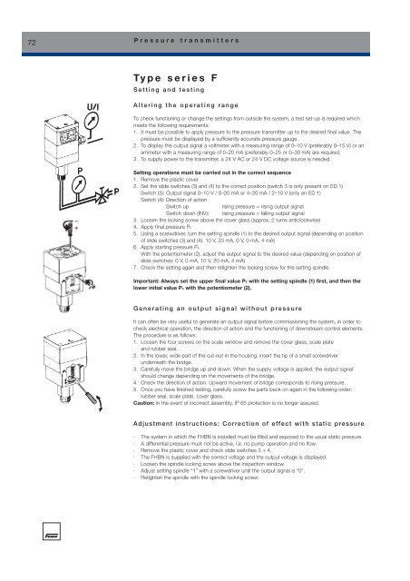
1. Remove the plastic cover<br />
2. Set the slide switches (3) and (4) to the correct position (switch 3 is only present on ED 1)<br />
Switch (3): Output signal 0–10 V / 0–20 mA or 4–20 mA / 2–10 V (only on ED 1)<br />
Switch (4): Direction of action<br />
Switch up<br />
rising pressure = rising output signal<br />
Switch down (INV): rising pressure = falling output signal<br />
3. Loosen the locking screw above the cover glass (approx. 2 turns anticlockwise)<br />
4. Apply final pressure PE<br />
5. Using a screwdriver, turn the setting spindle (1) to the desired output signal (depending on position<br />
of slide switches (3) and (4): 10 V, 20 mA, 0 V, 0 mA, 4 mA)<br />
6. Apply starting pressure PA<br />
With the potentiometer (2), adjust the output signal to the desired value (depending on position of<br />
slide switches: 0 V, 0 mA, 10 V, 20 mA, 4 mA)<br />
7. Check the setting again and then retighten the locking screw for the setting spindle.<br />
Important: Always set the upper final value PE with the setting spindle (1) first, and then the<br />
lower initial value PA with the potentiometer (2).<br />
Generating an output signal without pressure<br />
It can often be very useful to generate an output signal before commissioning the system, in order to<br />
check electrical operation, the direction of action and the functioning of downstream control elements.<br />
The procedure is as follows:<br />
1. Loosen the four screws on the scale window and remove the cover glass, scale plate<br />
and rubber seal.<br />
2. In the lower, wide part of the cut-out in the housing, insert the tip of a small screwdriver<br />
underneath the bridge.<br />
3. Carefully move the bridge up and down. When the supply voltage is applied, the output signal<br />
should change depending on the movements of the bridge.<br />
4. Check the direction of action. Upward movement of bridge corresponds to rising pressure.<br />
5. Once you have finished testing, carefully screw the parts back on again in the following order:<br />
rubber seal, scale plate, cover glass.<br />
Caution: In the event of incorrect assembly, IP 65 protection is no longer assured.<br />
Adjustment instructions: Correction of effect with static pressure<br />
· The system in which the FHBN is installed must be filled and exposed to the usual static pressure.<br />
· A differential pressure must not be active, i.e. no pump operation and no flow.<br />
· Remove the plastic cover and check slide switches 3 + 4.<br />
· The FHBN is supplied with the correct voltage and the output voltage is displayed.<br />
· Loosen the spindle locking screw above the inspection window.<br />
· Adjust setting spindle “1” with a screwdriver until the output signal is “0”.<br />
· Retighten the spindle with the spindle locking screw.