March 1, 2012 Mr. Shoukry Elnahal, PE Deputy ... - Town to Chatham
March 1, 2012 Mr. Shoukry Elnahal, PE Deputy ... - Town to Chatham
March 1, 2012 Mr. Shoukry Elnahal, PE Deputy ... - Town to Chatham

You also want an ePaper? Increase the reach of your titles
YUMPU automatically turns print PDFs into web optimized ePapers that Google loves.
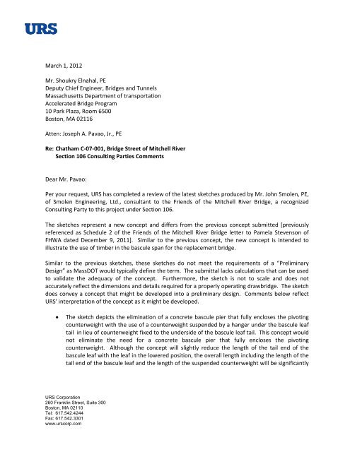
<strong>March</strong> 1, <strong>2012</strong><br />
<strong>Mr</strong>. <strong>Shoukry</strong> <strong>Elnahal</strong>, <strong>PE</strong><br />
<strong>Deputy</strong> Chief Engineer, Bridges and Tunnels<br />
Massachusetts Department of transportation<br />
Accelerated Bridge Program<br />
10 Park Plaza, Room 6500<br />
Bos<strong>to</strong>n, MA 02116<br />
Atten: Joseph A. Pavao, Jr., <strong>PE</strong><br />
Re: <strong>Chatham</strong> C‐07‐001, Bridge Street of Mitchell River<br />
Section 106 Consulting Parties Comments<br />
Dear <strong>Mr</strong>. Pavao:<br />
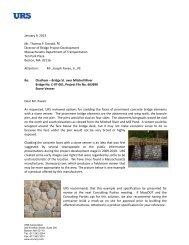
Per your request, URS has completed a review of the latest sketches produced by <strong>Mr</strong>. John Smolen, <strong>PE</strong>,<br />
of Smolen Engineering, Ltd., consultant <strong>to</strong> the Friends of the Mitchell River Bridge, a recognized<br />
Consulting Party <strong>to</strong> this project under Section 106.<br />
The sketches represent a new concept and differs from the previous concept submitted [previously<br />
referenced as Schedule 2 of the Friends of the Mitchell River Bridge letter <strong>to</strong> Pamela Stevenson of<br />
FHWA dated December 9, 2011]. Similar <strong>to</strong> the previous concept, the new concept is intended <strong>to</strong><br />
illustrate the use of timber in the bascule span for the replacement bridge.<br />
Similar <strong>to</strong> the previous sketches, these sketches do not meet the requirements of a “Preliminary<br />
Design” as MassDOT would typically define the term. The submittal lacks calculations that can be used<br />
<strong>to</strong> validate the adequacy of the concept. Furthermore, the sketch is not <strong>to</strong> scale and does not<br />
accurately reflect the dimensions and details required for a properly operating drawbridge. The sketch<br />
does convey a concept that might be developed in<strong>to</strong> a preliminary design. Comments below reflect<br />
URS’ interpretation of the concept as it might be developed.<br />
<br />
The sketch depicts the elimination of a concrete bascule pier that fully encloses the pivoting<br />
counterweight with the use of a counterweight suspended by a hanger under the bascule leaf<br />
tail in lieu of counterweight fixed <strong>to</strong> the underside of the bascule leaf tail. This concept would<br />
not eliminate the need for a concrete bascule pier that fully encloses the pivoting<br />
counterweight. Although the concept will slightly reduce the length of the tail end of the<br />
bascule leaf with the leaf in the lowered position, the overall length including the length of the<br />
tail end of the bascule leaf and the length of the suspended counterweight will be significantly<br />
URS Corporation<br />
260 Franklin Street, Suite 300<br />
Bos<strong>to</strong>n, MA 02110<br />
Tel: 617.542.4244<br />
Fax: 617.542.3301<br />
www.urscorp.com
Page 2 of 3<br />
longer with the bascule leaf in the raised position, which will require a deeper counterweight<br />
pit. (Note: The mass of a suspended counterweight is generally the same as the mass for a<br />
fixed counterweight. However, the suspended counterweight can be dimensioned with a<br />
shorter horizontal dimension and longer vertical dimension than a fixed counterweight.<br />
Because the suspended counterweight would be supported from a hanger, it pivots<br />
independently as the span operates and adds <strong>to</strong> the overall length of the bascule leaf tail with<br />
the span in the raised position.)<br />
<br />
<br />
<br />
<br />
The sketch depicts the bascule span superstructure supported on a pile bent with concrete cap<br />
and battered piles. This configuration is unlikely <strong>to</strong> provide adequate stiffness <strong>to</strong> limit lateral<br />
deflections and is likely <strong>to</strong> result in conditions where the tip end of the bascule leaf will contact<br />
the fixed span superstructure at the rest pier. Significant longitudinal bracing between pile<br />
bents would be necessary <strong>to</strong> stiffen this configuration. The need for a concrete bascule pier<br />
that fully encloses the pivoting counterweight supersedes the use of this pile bent<br />
configuration.<br />
The sketch does not depict the mechanism that would be used <strong>to</strong> operate the span. Because<br />
the concept proposes timber beams for the bascule leaf superstructure and timber beams do<br />
not have adequate strength <strong>to</strong> cantilever from the pivot <strong>to</strong> the tip is the bridge operates, a<br />
cable operated drive system, similar <strong>to</strong> the existing bridge, with the cables attached <strong>to</strong> the tip<br />
end of the bascule leaf would be required. The concerns with a cable operated drive system<br />
have been well documented in previous correspondence.<br />
The sketch depicts the use of steel tubes <strong>to</strong> strengthen timber beams from the pivot <strong>to</strong> the tail<br />
end of the bascule leaf. This does not address the limited capacity of timber beams <strong>to</strong><br />
cantilever from the pivot <strong>to</strong> the tip end of the leaf. The steel tubes would need <strong>to</strong> extend a<br />
significant length forward of the pivot (i.e. 2/3 <strong>to</strong> 3/4 the length of the span) <strong>to</strong> provide the<br />
required strength, if this is the intent. The steel tubes would completely hide the timber for a<br />
majority of the span thus making the timber inaccessible for maintenance and inspection. It is<br />
expected that the timber will not fit tightly within the steel tubes and as such will permit<br />
moisture <strong>to</strong> enter the space between the timber and steel tube. This moisture will promote<br />
decay of the wood and corrosion of the interior surfaces of the steel tubes.<br />
The sketch depicts the cantilevered tail end of the bascule leaf supporting the roadway deck.<br />
It is anticipated that the deflection of the beams under traffic loading will result in a significant<br />
undesirable discontinuity in the deck as traffic crosses the joint between the fixed approach<br />
span and bascule leaf tail. In addition, traffic on the cantilevered tail end of the bascule leaf<br />
will act <strong>to</strong> lift the tip end of the leaf. In order <strong>to</strong> address these issues, operating locking<br />
devices at the tail end and tip end of the leaf would be required. Alternatively, if the beams on<br />
the fixed approach deck were <strong>to</strong> overlap with the beams on the bascule leaf tail, similar <strong>to</strong> the
Page 3 of 3<br />
existing bridge, a deck flap similar <strong>to</strong> the existing bridge, but much larger in width and length<br />
and thus much heavier than the existing, will be required <strong>to</strong> permit the bridge <strong>to</strong> be operated.<br />
As with all bascule spans, the details of the design must be evaluated closely even at the conceptual<br />
level <strong>to</strong> confirm that the concept is appropriate and practical.<br />
In consideration of the complex design and associated detail challenges, the aesthetic challenges,<br />
increased maintenance for the <strong>Town</strong> of <strong>Chatham</strong> and potential for safety issues, URS does not<br />
recommend pursuing this concept.<br />
Sincerely,<br />
URS Corporation<br />
Mark E. Shamon, <strong>PE</strong><br />
Vice President, Engineering Services<br />
Enclosure