AR-B6050 Board User Manual
Download - Acrosser
Download - Acrosser
- No tags were found...

You also want an ePaper? Increase the reach of your titles
YUMPU automatically turns print PDFs into web optimized ePapers that Google loves.
<strong>AR</strong>-<strong>B6050</strong> <strong>User</strong> <strong>Manual</strong><br />
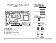
<strong>AR</strong>-<strong>B6050</strong> <strong>Board</strong><br />
Fan-less with Intel ATOM Pineview + ICH8M<br />
<strong>User</strong> <strong>Manual</strong><br />
<strong>Manual</strong> Rev.: 1.0<br />
Book Number: <strong>AR</strong>-<strong>B6050</strong>-2010.07.27<br />
1
<strong>AR</strong>-<strong>B6050</strong> <strong>User</strong> <strong>Manual</strong><br />
Revision<br />
Version Date Author Description<br />
1.0 2010/07/27 Cody Dai Draft<br />
2
<strong>AR</strong>-<strong>B6050</strong> <strong>User</strong> <strong>Manual</strong><br />
Copyright 2010<br />
All Rights Reserved.<br />
<strong>Manual</strong>’s first edition:<br />
For the purpose of improving reliability, design and function, the information in this document is<br />
subject to change without prior notice and does not represent a commitment on the part of the<br />
manufacturer.<br />
In no event will the manufacturer be liable for direct, indirect, special, incidental, or<br />
consequential damages arising out of the use or inability to use the product or documentation, even<br />
if advised of the possibility of such damages.<br />
This document contains proprietary information protected by copyright. All rights are reserved.<br />
No part of this <strong>Manual</strong> may be reproduced by any mechanical, electronic, or other means in any<br />
form without prior written permission of the manufacturer.<br />
Trademarks<br />
<strong>AR</strong>-<strong>B6050</strong> is a registered trademarks of Acrosser; IBM PC is a registered trademark of the<br />
International Business Machines Corporation; Pentium is a registered trademark of Intel<br />
Technologies Inc; Award is a registered trademark of Award Software International Inc; other<br />
product names mentioned herein are used for identification purposes only and may be trademarks<br />
and/or registered trademarks of their respective companies.<br />
3
<strong>AR</strong>-<strong>B6050</strong> <strong>User</strong> <strong>Manual</strong><br />
Table of Contents<br />
1 Introduction .............................................................................5<br />
1.1 Specifications.................................................................................................6<br />
1.2 Package Contents ..........................................................................................7<br />
1.3 Block Diagram ................................................................................................8<br />
2 H/W Information.......................................................................9<br />
2.1 Locations of Connector and Jumper Setting ...............................................9<br />
2.2 Connector and Jumper Setting Table .........................................................12<br />
3 BIOS Setting .......................................................................... 16<br />
3.1 Main Setup....................................................................................................17<br />
3.2 Advanced Chipset Setup .............................................................................19<br />
3.3 Peripherals Setup.........................................................................................20<br />
3.4 Power Setup .................................................................................................22<br />
3.5 Boot Setup....................................................................................................23<br />
3.6 Exit Setup......................................................................................................24<br />
4 WATCHDOG, GPIO, AND BYPASS PROGRAMMING........... 25<br />
4.1 Watchdog Programming..............................................................................25<br />
4.2 GPIO Programming ......................................................................................29<br />
4
<strong>AR</strong>-<strong>B6050</strong> <strong>User</strong> <strong>Manual</strong><br />
1 INTRODUCTION<br />
<strong>AR</strong>-<strong>B6050</strong> is a 3.5” SBC board that is designed with Intel Atom N450 and supports up to 2GB<br />
of DDR2 667Mhz memory. <strong>AR</strong>-<strong>B6050</strong> has diverse physical interface for different peripheral, e.g.<br />
VGA port, LVDS port, 6 * USB 2.0 ports, 2 * COM ports, 2 * Gbps ports, 2 * SATA ports, CF type I/II<br />
slot and Realtek audio output port. It is also equipped with industrial standard PCI-104 and<br />
miniPCIe interface. <strong>User</strong>s can purchase suitable add-on cards to satisfy their needs.<br />
5
<strong>AR</strong>-<strong>B6050</strong> <strong>User</strong> <strong>Manual</strong><br />
1.1 Specifications<br />
<br />
IntelR Atom N450 1.66GHz<br />
IntelR Graphics Media Accelerator 950<br />
<br />
<br />
<br />
<br />
<br />
<br />
<br />
<br />
<br />
1 x SO-DIMM supports DDRII up to 2GB(Memory DDR2 data transfer rates of 667 MT/s)<br />
1 x VGA<br />
4 x USB2.0<br />
2 x SATA<br />
1 x CF II<br />
2 x RS-232<br />
2 x GbE (Realtek RTL8111D)<br />
1 x PCI-104 & 1 x Mini-PCIe<br />
8-bit GPIO<br />
6
<strong>AR</strong>-<strong>B6050</strong> <strong>User</strong> <strong>Manual</strong><br />
1.2 Package Contents<br />
Check if the following items are included in the package.<br />
<br />
<br />
<br />
Quick <strong>Manual</strong><br />
<strong>AR</strong>-<strong>B6050</strong><br />
1 x Software Utility CD<br />
7
<strong>AR</strong>-<strong>B6050</strong> <strong>User</strong> <strong>Manual</strong><br />
1.3 Block Diagram<br />
8
<strong>AR</strong>-<strong>B6050</strong> <strong>User</strong> <strong>Manual</strong><br />
2 H/W INFORMATION<br />
This chapter describes the installation of <strong>AR</strong>-<strong>B6050</strong>. At first, it shows the Function diagram and<br />
the layout of <strong>AR</strong>-<strong>B6050</strong>. It then describes the unpacking information which you should read carefully,<br />
as well as the jumper/switch settings for the <strong>AR</strong>-<strong>B6050</strong> configuration<br />
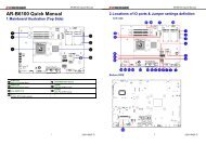
2.1 Locations of Connector and Jumper Setting<br />
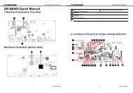
2.1.1 Locations (Top side)<br />
9
<strong>AR</strong>-<strong>B6050</strong> <strong>User</strong> <strong>Manual</strong><br />
JP1 COM1 VGA1<br />
ATX1 COM2 J1<br />
BAT1 SATA2 USB3<br />
SYSFAN1 SATA1 USB1<br />
CN2 CN4 USB2<br />
CN3 JP3 LED1<br />
JP2 LAN1 LVDS1<br />
J7 LAN2 CN1<br />
GPIO1<br />
J6<br />
10
<strong>AR</strong>-<strong>B6050</strong> <strong>User</strong> <strong>Manual</strong><br />
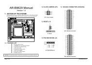
2.1.2 Locations (Bottom Side)<br />
SODIMM1<br />
CF<br />
11
<strong>AR</strong>-<strong>B6050</strong> <strong>User</strong> <strong>Manual</strong><br />
2.2 Connector and Jumper Setting Table<br />
1. JP1: LCD panel driving<br />
voltage selection.<br />
2. ATX1: AT power input<br />
connector.<br />
3. BAT1: CMOS battery holder.<br />
STATUS SETTING<br />
+3.3V<br />
1-2<br />
(Default).<br />
2-3 +5V<br />
PIN SETTING<br />
1 GND<br />
2 GND<br />
3 +12V<br />
4 +12V<br />
CMOS battery holder.<br />
4. SYSFAN1: System DC<br />
Fan connector.<br />
5. CN2: PCI-104 connector. 6. CN3: MINI PCI-E connector.<br />
PIN<br />
SETTING<br />
1 GND<br />
2 +12V<br />
3 Fan speed data<br />
PCI-104 connector.<br />
MINI PCI-E connector.<br />
7. JP2: Signal SERIRQ<br />
connects to PCI-104 pin<br />
#B1 selection.<br />
8. J7: COM1/2 SELECT RI OR<br />
+12V<br />
9. GPIO1: GPIO connector.<br />
STATUS<br />
Open<br />
Short<br />
SETTING<br />
Disconnected.<br />
(Default)<br />
Connected.<br />
PIN SIGNAL PIN SIGNAL<br />
1 RI#1 2 RI#1_12V<br />
3 +12V 4 RI#1_12V<br />
5 RI#2 6 RI#2_12V<br />
7 +12V 8 RI#2_12V<br />
PIN SETTING PIN SETTING<br />
1 GPIO0 2 +5V<br />
3 GPIO1 4 GPIO7<br />
5 GPIO2 6 GPIO6<br />
7 GPIO3 8 GPIO5<br />
9 GND 10 GPIO4<br />
12
<strong>AR</strong>-<strong>B6050</strong> <strong>User</strong> <strong>Manual</strong><br />
10. COM1: RS232 signal<br />
connector for port #1.<br />
11. COM2: RS232 signal<br />
connector for port #2.<br />
12. SATA1: SATA device<br />
connector #1.<br />
PIN SETTING PIN SETTING<br />
1 DCD #1 2 DSR #1<br />
3 RX #1 4 RTS #1<br />
5 TX #1 6 CTS #1<br />
7 DTR #1 8 RI #1<br />
9 GND 10 GND<br />
PIN SETTING PIN SETTING<br />
1 DCD #2 2 DSR #2<br />
3 RX #2 4 RTS #2<br />
5 TX #2 6 CTS #2<br />
7 DTR #2 8 RI #2<br />
9 GND 10 GND<br />
SATA device connector<br />
#1.<br />
13. SATA2: SATA device<br />
connector #2.<br />
14. CN4: Audio signal<br />
connector.<br />
15. JP3: CF MASTER<br />
SELECT<br />
SET<br />
SIGNAL<br />
SATA device connector #2.<br />
Audio line out<br />
SHORT<br />
MASTER<br />
OPEN<br />
SLAVE<br />
16. LAN1: RJ45 connector for<br />
Gigabit Ethernet port #1.<br />
17. LAN2: RJ45 connector for<br />
Gigabit Ethernet port #2.<br />
18. J6: Front panel<br />
connector.<br />
STATUS<br />
SETTING<br />
RJ45 connector for Gigabit<br />
Ethernet port #1.<br />
RJ45 connector for<br />
Gigabit Ethernet port #2.<br />
1-2 Hardware reset<br />
AT Mode - Short<br />
3-4<br />
ATX Mode - Open<br />
5-6 Power Button<br />
13
<strong>AR</strong>-<strong>B6050</strong> <strong>User</strong> <strong>Manual</strong><br />
19. VGA1: D-SUB-15 female<br />
connector for VGA output.<br />
20. J1: CMOS data clear 21. USB3: Internal USB2.0<br />
connector<br />
D-SUB-15 female connector<br />
for VGA output.<br />
SHORT CMOS data clear<br />
PIN SETTING PIN SETTING<br />
1 +5V 2 +5V<br />
3 USB5- 4 USB6-<br />
5 USB5+ 6 USB6+<br />
7 GND 8 GND<br />
9 GND 10 GND<br />
22. USB1: USB connector 23. USB2: USB connector 24. LED1: System power and<br />
HDD access indicators.<br />
Green: System power<br />
Upper: Port #2.<br />
Lower: Port #1.<br />
Upper: Port #4.<br />
Lower: Port #3.<br />
indicator.<br />
Yellow: HDD access<br />
indicator.<br />
25. LVDS1: LCD panel inverter<br />
power connector.<br />
26. CN1: LCD panel inverter<br />
power connector.<br />
PIN SETTING PIN SETTING<br />
1 LCD VDD 2 GND<br />
3 NC 4 NC<br />
5 GND 6 NC<br />
7 NC 8 GND<br />
PIN<br />
SETTING<br />
9 NC 10 NC<br />
11 NC 12 NC<br />
13 NC 14 NC<br />
15 GND 16 O CLK+<br />
17 CLK- 18 GND<br />
19 Data2+ 20 Data2-<br />
1 +12V<br />
2 +12V<br />
3 GND<br />
4 BKL ON<br />
5 GND<br />
6 Reserved.<br />
21 I2C CLK 22 Data1+<br />
23 Data1- 24 I2C Data<br />
25 Data0+ 26 Data0-<br />
27 NC 28 NC<br />
29 LCD VDD 30 LCD VDD<br />
14
<strong>AR</strong>-<strong>B6050</strong> <strong>User</strong> <strong>Manual</strong><br />
27. DIMM1: DDR-II SODIMM<br />
Socket.<br />
28. CF1: Type-II compact flash<br />
card socket.<br />
DDR-II SODIMM<br />
Socket.<br />
+3.3V CF card only and<br />
UDMA mode supported.<br />
15
<strong>AR</strong>-<strong>B6050</strong> <strong>User</strong> <strong>Manual</strong><br />
3 BIOS SETTING<br />
The BIOS Setup Utility is a hardware configuration program built into your computer’s BIOS.<br />
To activate the BIOS Utility, press F2 during POST (when “Press to enter Setup”<br />
message is prompted on the bottom of screen).<br />
Press during POST to enter multi-boot menu. In this menu, user can change boot<br />
device without entering BIOS SETUP Utility.<br />
This chapter describes the BIOS menu displays and explains how to perform common tasks<br />
needed to get the system up and running. It also gives detailed explanation of the elements found in<br />
each of the BIOS menu. The following topics are covered:<br />
<br />
<br />
<br />
<br />
<br />
<br />
Main Setup<br />
Advanced Setup<br />
Security Setup<br />
Power Setup<br />
Boot Setup<br />
Exit Setup<br />
16
<strong>AR</strong>-<strong>B6050</strong> <strong>User</strong> <strong>Manual</strong><br />
3.1 Main Setup<br />
Once you enter the InsydeH2O BIOS Setup Utility, the Main Menu will appear on the screen.<br />
Use the arrow keys to highlight the item and then use the keys to select the desired<br />
value in each item.<br />
Note: The control keys are listed at the bottom of the menu. If you need any help with the item fields, you can<br />
press the key, and the relevant information will be displayed.<br />
Item Option Description<br />
Set the system date. Note that the ‘Day’<br />
Format : MM/DD/YYYY<br />
System Date<br />
automatically changes when you set the<br />
(month/day/year)<br />
date.<br />
Format: HH:MM:SS<br />
System Time<br />
Set the system time.<br />
(hour:minute:second)<br />
Processor<br />
Type<br />
N/A<br />
This field shows the CPU type and speed<br />
of the system.<br />
17
<strong>AR</strong>-<strong>B6050</strong> <strong>User</strong> <strong>Manual</strong><br />
System Bus<br />
Speed<br />
System<br />
Memory<br />
Speed<br />
Cache RAM<br />
N/A<br />
N/A<br />
N/A<br />
This field displays the bus speed of the<br />
system.<br />
This field displays the real speed of the<br />
memory.<br />
This field displays the cache ram of the<br />
CPU.<br />
Total Memory N/A Displays the total memory available.<br />
SODIMM 0<br />
N/A<br />
This field displays the memory of the<br />
SODIMM0.<br />
BIOS Revision N/A Displays system BIOS version.<br />
18
<strong>AR</strong>-<strong>B6050</strong> <strong>User</strong> <strong>Manual</strong><br />
3.2 Advanced Chipset Setup<br />
Note: The control keys are listed at the bottom of the menu. If you need any help with the item fields, you can<br />
press the key, and the relevant information will be displayed.<br />
Item Option Description<br />
Serial Port A<br />
Peripheral<br />
Enter the Peripheral Configuration<br />
Serial Port B<br />
Configuration<br />
menu.<br />
Azalia Audio control<br />
IDE<br />
IDE Controller<br />
Enter the IDE Configuration menu.<br />
Configuration HDC Configure as<br />
Init Display First<br />
IGD-Device2, Function1<br />
Video IGD-Frame Buffer Size<br />
Enter the Video Configuration menu.<br />
Configuration IGD-DVMT Size<br />
IGD-Boot Type<br />
IGD-LCD Panel type<br />
Hardware<br />
Monitor<br />
N/A<br />
This field displays the Hardware<br />
Monitor of the system.<br />
19
<strong>AR</strong>-<strong>B6050</strong> <strong>User</strong> <strong>Manual</strong><br />
3.3 Peripherals Setup<br />
Note: The control keys are listed at the bottom of the menu. If you need any help with the item fields, you can<br />
press the key, and the relevant information will be displayed.<br />
Item Option Description<br />
Supervisor<br />
Password<br />
Not Installed<br />
Installed<br />
Shows the setting of the Supervisor<br />
password<br />
Set<br />
Supervisor<br />
Password<br />
N/A<br />
Press Enter to set the user password. When<br />
user<br />
password is set, this password protects the<br />
BIOS Setup<br />
Utility from unauthorized access. The user<br />
can enter<br />
Setup menu only and does not have right to<br />
change the<br />
value of parameters.<br />
20
<strong>AR</strong>-<strong>B6050</strong> <strong>User</strong> <strong>Manual</strong><br />
Setting a Password<br />
Follow these steps as you set the user or the supervisor password:<br />
1. Use the ↑ and ↓ keys to highlight the Set Supervisor Password parameter and press the Enter key.<br />
The Set Supervisor Password box appears:<br />
2. Type a password in the “Enter New Password” field. The password length can not exceed 8<br />
alphanumeric characters (A-Z, a-z, 0-9, not case sensitive). Retype the password in the “Confirm New<br />
Password” field.<br />
IMPORTANT:Be very careful when typing your password because the characters do not appear on the<br />
screen.<br />
3. Press Enter. After setting the password, the computer sets the <strong>User</strong> Password parameter to “Set”.<br />
4. If desired, you can opt to enable the Password on boot parameter.<br />
5. When you are done, press F10 to save the changes and exit the BIOS Setup Utility.<br />
Removing a Password<br />
Follow these steps:<br />
1. Use the ↑ and ↓ keys to highlight the Set Supervisor Password parameter and press the Enter key.<br />
The Set Password box appears:<br />
2. Type the current password in the Enter Current Password field and press Enter.<br />
3. Press Enter twice without typing anything in the Enter New Password and Confirm New Password<br />
fields. The computer then sets the Supervisor Password parameter to “Clear”.<br />
4. When you have changed the settings, press u to save the changes and exit the BIOS Setup Utility.<br />
21
<strong>AR</strong>-<strong>B6050</strong> <strong>User</strong> <strong>Manual</strong><br />
3.4 Power Setup<br />
Note: The control keys are listed at the bottom of the menu. If you need any help with the item fields, you can<br />
press the key, and the relevant information will be displayed.<br />
Item Option Description<br />
ACPI S3<br />
Enabled<br />
ACPI S1/S3 Sleep State.<br />
Support<br />
Disabled<br />
Wake up when the system power is off<br />
Wakeup on<br />
Enabled<br />
and a PCI Power Management Enable<br />
PME<br />
Disabled<br />
wake up event occurs.<br />
22
<strong>AR</strong>-<strong>B6050</strong> <strong>User</strong> <strong>Manual</strong><br />
3.5 Boot Setup<br />
Note: The control keys are listed at the bottom of the menu. If you need any help with the item fields, you can<br />
press the key, and the relevant information will be displayed.<br />
Item Option Description<br />
Select Boot Devices to select specific<br />
Boot Device<br />
N/A devices to support boot.<br />
Priority<br />
(The item can't display when no device.)<br />
Hard disk<br />
Drive<br />
CD/DVD-ROM<br />
Drive<br />
USB Drive<br />
Other<br />
PXE Boot to<br />
LAN<br />
N/A<br />
N/A<br />
N/A<br />
N/A<br />
Enabled<br />
Disabled<br />
Show the Hard disk drives.<br />
(The item can't display when no device.)<br />
Show the CD/DVD-ROM drives.<br />
(The item can't display when no device.)<br />
Show the USB diskette drives.<br />
(The item can't display when no device.)<br />
Show the other drives.<br />
(The item can't display when no device.)<br />
Disables or enables PXE boot to LAN.<br />
23
<strong>AR</strong>-<strong>B6050</strong> <strong>User</strong> <strong>Manual</strong><br />
3.6 Exit Setup<br />
Note: The control keys are listed at the bottom of the menu. If you need any help with the item fields, you can<br />
press the key, and the relevant information will be displayed.<br />
Item Option Description<br />
Exit Saving<br />
Yes<br />
changes<br />
NO<br />
Exit System Setup and save your changes.<br />
Save change<br />
without Exit<br />
Yes<br />
NO<br />
Save Your changes and without exiting<br />
system.<br />
Exit<br />
Yes Exit system setup and without saving your<br />
Discarding<br />
NO changes.<br />
changes<br />
Load Optimal<br />
Defaults<br />
Discarding<br />
changes<br />
Yes<br />
NO<br />
Yes<br />
NO<br />
Load default values for all SETUP item.<br />
Load previous values from CMOS for all<br />
SETUP items.<br />
24
<strong>AR</strong>-<strong>B6050</strong> <strong>User</strong> <strong>Manual</strong><br />
4<br />
WATCHDOG, GPIO, AND BYPASS<br />
PROGRAMMING<br />
4.1 Watchdog Programming<br />
This section describes the usage of WATCHDOG. <strong>AR</strong>-<strong>B6050</strong> integrated the WATCHDOG that<br />
enable user to reset the system after a time-out event. <strong>User</strong> can use a program to enable the<br />
WATCHDOG and program the timer in range of 1~255 second(s)/minute(s). Once user enables the<br />
WATCHDOG, the timer will start to count down to zero except trigger the timer by user’s program<br />
continuously. After zeroize the timer (stop triggering), the WATCHDOG will generate a signal to<br />
reset the system. It can be used to prevent system crash or hang up. The WATCHDOG is disabled<br />
after reset and should be enabled by user’s program.<br />
Intel also provides a Linux watchdog driver to access the feature on <strong>AR</strong>-<strong>B6050</strong>. It can be accessed<br />
via /dev/watchdog. About the related operations of Linux watchdog, please refer Linux website.<br />
Please refer to the following table to program WATCHDOG properly, and user could test<br />
WATCHDOG under ‘Debug’ program.<br />
C:>debug To enter debug mode.<br />
-o 2E 87<br />
Address port: 2E and Data port: 2F<br />
-o 2E 01<br />
-o 2E 55<br />
-o 2E 55<br />
To enter configuration.<br />
-o 2E 07 To point to Logical Device Number Reg.<br />
-o 2F 07 To select logical device 7 (WATCHDOG).<br />
-o 2E 72<br />
-o 2F 40<br />
To select “keyboard reset” as WATCHDOG output to reset system.<br />
-o 2E 72 Preparing to select the unit of timer equals minute or second.<br />
-i 2F To read the value of index “2F”.<br />
-o 2F xx The value “xx” equals [(value of index “2F”) OR (80)].<br />
OR (80): unit is second.<br />
OR (00): unit is minute.<br />
-o 2E 73 Preparing to set the WATCHDOG timer value.<br />
25
<strong>AR</strong>-<strong>B6050</strong> <strong>User</strong> <strong>Manual</strong><br />
-o 2F ## The value “##” ranges between 01 ~ FF (1 ~ 255 seconds).<br />
00: To disable WATCHDOG.<br />
-q To quit debug mode<br />
Notice: The “actual” timer value may not match with the “theoretical”. That is because of the<br />
tolerance of internal oscillating clock and cannot be adjusted or optimized.<br />
The WATCHDOG sample code of C language as below:<br />
//=========================================================================<br />
==<br />
// Rev Date Name Description<br />
//=========================================================================<br />
==<br />
// 1.0 12/16/2009 Willy W83627EHF WatchDog timer test<br />
//=========================================================================<br />
==<br />
//=========================================================================<br />
==<br />
// Language include files<br />
//=========================================================================<br />
==<br />
#include <br />
#include <br />
#include <br />
#include <br />
//=========================================================================<br />
==<br />
// Normal procedure<br />
//=========================================================================<br />
==<br />
void Show_Help();<br />
//=========================================================================<br />
==<br />
26
<strong>AR</strong>-<strong>B6050</strong> <strong>User</strong> <strong>Manual</strong><br />
// Main procedure<br />
//=========================================================================<br />
==<br />
int main(int argc, char *argv[])<br />
{<br />
unsigned char IO_Port_Address=0x2E;<br />
unsigned char Time;<br />
unsigned char Temp;<br />
if ( argc != 2 )<br />
{ Show_Help(); return 1; }<br />
clrscr();<br />
Time=atoi(argv[1]);<br />
// Set Watchdog<br />
outportb(IO_Port_Address,0x87);<br />
outportb(IO_Port_Address,0x87);<br />
// (EFER) Extended Functions Enable Register<br />
outportb(IO_Port_Address,0x2D); // Point to Global Reg.<br />
// Select Multi-Function pin, (Bit0=0 Watchdog Function)<br />
outportb(IO_Port_Address+1,(inportb(IO_Port_Address+1)&0xFE));<br />
outportb(IO_Port_Address,0x07);<br />
// Point to Logical Device Number Reg.<br />
outportb(IO_Port_Address+1,0x08); // Select logical device 8, (Watchdog Function)<br />
outportb(IO_Port_Address,0x30);<br />
outportb(IO_Port_Address+1,0x01);<br />
// Device Active register<br />
outportb(IO_Port_Address,0xF5);<br />
outportb(IO_Port_Address+1,0x02);<br />
// Select Watchdog count mode seconds or minutes<br />
// Default is second and KBRST mode.<br />
outportb(IO_Port_Address,0xF6);<br />
// Set Watchdog Timer Value<br />
outportb(IO_Port_Address+1,Time); // 0x00 to disable, max 0xFF<br />
textcolor(YELLOW);<br />
27
<strong>AR</strong>-<strong>B6050</strong> <strong>User</strong> <strong>Manual</strong><br />
for(Temp=Time;Temp>0;Temp--)<br />
{<br />
outportb(IO_Port_Address,0xF6); // Read Watchdog Timer Value<br />
Time=inportb(IO_Port_Address+1);<br />
gotoxy(20,10);<br />
cprintf(">>> After %3d Second will reset the system.
<strong>AR</strong>-<strong>B6050</strong> <strong>User</strong> <strong>Manual</strong><br />
4.2 GPIO Programming<br />
This section describes the usage of GPIOs. <strong>AR</strong>-<strong>B6050</strong> integrated eight bits, 5V TTL level,<br />
bidirectional, and software programmable GPIOs for user’s application. They are all capable of 5<br />
mA source current for output and 8 mA sink current for input individually. The electrical<br />
characteristics of GPIOs as following table:<br />
PIN SIGNAL PIN SIGNAL<br />
1 GPO0 2 VCC<br />
3 GPO7 4 GPI7<br />
5 GPO2 6 GPI6<br />
7 GPO3 8 GPI5<br />
9 GND 10 GPI4<br />
To quickly understand the GPIO programming under Linux, we also provide a sample application<br />
source code in product CD, naming gpio.c. It can be used to control GPIO pin described above and<br />
also LED.<br />
The GPIO sample code of C language as below:<br />
//=========================================================================<br />
==<br />
// Rev Date Name Description<br />
//=========================================================================<br />
==<br />
// 1.0 03/17/10 Willy GPIO10~GPIO17 Test utility for W83627EHF.<br />
//=========================================================================<br />
==<br />
//=========================================================================<br />
==<br />
// Turbo C++ Version 3.0 Copyright(c) 1990, 1992 by Borland International,Inc.<br />
//=========================================================================<br />
==<br />
//=========================================================================<br />
==<br />
// Language include files<br />
//=========================================================================<br />
29
<strong>AR</strong>-<strong>B6050</strong> <strong>User</strong> <strong>Manual</strong><br />
==<br />
#include <br />
#include <br />
//=========================================================================<br />
==<br />
// Normal procedure<br />
//=========================================================================<br />
==<br />
void Show_Help();<br />
void Show_Fail();<br />
void Show_Pass();<br />
//=========================================================================<br />
==<br />
// Main procedure<br />
//=========================================================================<br />
==<br />
int main(int argc)<br />
{<br />
char *Model_Name="<strong>AR</strong>-<strong>B6050</strong>";<br />
char *Version="v1.0";<br />
unsigned char IO_PORT_BASE=0x2E; // DATA_PORT = IO_PORT_BASE + 1;<br />
unsigned char data;<br />
int result=0;<br />
if ( argc > 1 )<br />
{ Show_Help(); return 1; }<br />
clrscr();<br />
textcolor(WHITE);<br />
gotoxy(1, 1);<br />
cprintf("===================================================================<br />
=======");<br />
gotoxy(1, 2); cprintf("|| W83627EHF GPIO Test Utility %s Acrosser Technology Co., Ltd.<br />
||",Version);<br />
gotoxy(1, 3);<br />
cprintf("===================================================================<br />
30
<strong>AR</strong>-<strong>B6050</strong> <strong>User</strong> <strong>Manual</strong><br />
=======");<br />
gotoxy(1, 4);<br />
cprintf("===================================================================<br />
=======");<br />
gotoxy(1, 5); cprintf("|| Model Name :<br />
||");<br />
gotoxy(1, 6); cprintf("|| SIO IO Base :<br />
||");<br />
gotoxy(1, 7);<br />
cprintf("===================================================================<br />
=======");<br />
// Show Got Parameter Informat<br />
textcolor(LIGHTGRAY);<br />
gotoxy(18,5); cprintf("%s",Model_Name);<br />
gotoxy(18,6); cprintf("%X",IO_PORT_BASE);<br />
// Enter W83627EHF Config<br />
outportb(IO_PORT_BASE,0x87);<br />
outportb(IO_PORT_BASE,0x87);<br />
// Set Multi-function Pins to GPIO<br />
outportb(IO_PORT_BASE,0x29);<br />
outportb(IO_PORT_BASE+1,(inportb(IO_PORT_BASE+1) | 0x01));<br />
// Select GPIO Port device<br />
outportb(IO_PORT_BASE,0x07);<br />
outportb(IO_PORT_BASE+1,0x07);<br />
// Set GPIO Port Active<br />
outportb(IO_PORT_BASE,0x30);<br />
outportb(IO_PORT_BASE+1,0x01);<br />
// Set GPIO I/O Register to 00h<br />
outportb(IO_PORT_BASE,0xF3);<br />
outportb(IO_PORT_BASE+1,0x00);<br />
// Set W83627EHF GPIO10~13 to Output, GPIO14~GPIO17 to Input<br />
31
<strong>AR</strong>-<strong>B6050</strong> <strong>User</strong> <strong>Manual</strong><br />
outportb(IO_PORT_BASE,0xF0);<br />
outportb(IO_PORT_BASE+1,0xF0);<br />
// Set W83627EHF GPIO10~13 to High<br />
outportb(IO_PORT_BASE,0xF1);<br />
outportb(IO_PORT_BASE+1,0x0F);<br />
// Read W83627EHF GPIO14~17 Status, if not High error.<br />
data=inportb(IO_PORT_BASE+1)&0xF0;<br />
if(data!=0xF0)<br />
result=1;<br />
// Set W83627EHF GPIO10~13 to Low<br />
outportb(IO_PORT_BASE,0xF1);<br />
outportb(IO_PORT_BASE+1,0x00);<br />
// Read W83627EHF GPIO14~17 Status, if not Low error.<br />
data=inportb(IO_PORT_BASE+1)&0xF0;<br />
if(data!=0x00)<br />
result=1;<br />
// Set W83627EHF GPIO10~13 to input, GPIO14~GPIO17 to Output<br />
outportb(IO_PORT_BASE,0xF0);<br />
outportb(IO_PORT_BASE+1,0x0F);<br />
// Set W83627EHF GPIO14~17 to High<br />
outportb(IO_PORT_BASE,0xF1);<br />
outportb(IO_PORT_BASE+1,0xF0);<br />
// Read W83627EHF GPIO10~13 Status, if not High error.<br />
data=inportb(IO_PORT_BASE+1)&0x0F;<br />
if(data!=0x0F)<br />
result=1;<br />
// Set W83627EHF GPIO14~17 to Low<br />
outportb(IO_PORT_BASE,0xF1);<br />
outportb(IO_PORT_BASE+1,0x00);<br />
// Read W83627EHF GPIO14~17 Status, if not Low error.<br />
data=inportb(IO_PORT_BASE+1)&0x0F;<br />
if(data!=0x00)<br />
result=1;<br />
// Exit W83627EHF Config<br />
32
<strong>AR</strong>-<strong>B6050</strong> <strong>User</strong> <strong>Manual</strong><br />
outportb(IO_PORT_BASE,0xAA);<br />
if(result)<br />
Show_Fail();<br />
else<br />
Show_Pass();<br />
}<br />
return result;<br />
//=========================================================================<br />
==<br />
// Function : Show_Help()<br />
// Input : -<br />
// Change : -<br />
// Return : -<br />
// Description : Show Title string.<br />
//=========================================================================<br />
==<br />
void Show_Help()<br />
{<br />
}<br />
clrscr();<br />
printf("GPIO Test utility for W83627EHF\n\n");<br />
printf("GPIO0 迋 迋 迋 芼 Vcc\n");<br />
printf("GPIO1 迋 迋 迋 銀 迋 迋 GPIO7\n");<br />
printf("GPIO2 迋 迋 芼 迋 迋 GPIO6\n");<br />
printf("GPIO3 迋 迋 銀 迋 迋 迋 GPIO5\n");<br />
printf("GND<br />
<br />
迋 迋 迋 GPIO4\n");<br />
//=========================================================================<br />
==<br />
// Function : Show_Fail()<br />
// Input : -<br />
// Change : -<br />
// Return : -<br />
// Description : Show Fail Message.<br />
//=========================================================================<br />
33
<strong>AR</strong>-<strong>B6050</strong> <strong>User</strong> <strong>Manual</strong><br />
==<br />
void Show_Fail()<br />
{<br />
}<br />
textcolor(LIGHTRED);<br />
gotoxy(20,10); cprintf(" 詗 詗 詗 詗 詗 詗 詗 詗 詗 詗 ");<br />
gotoxy(20,11); cprintf(" 詗 詗 詗 詗 詗 ");<br />
gotoxy(20,12); cprintf(" 詗 詗 詗 詗 詗 詗 詗 詗 詗 ");<br />
gotoxy(20,13); cprintf(" 詗 詗 詗 詗 詗 ");<br />
gotoxy(20,14); cprintf(" 詗 詗 詗 詗 詗 詗 詗 詗 詗 ");<br />
//=========================================================================<br />
==<br />
// Function : Show_Pass()<br />
// Input : -<br />
// Change : -<br />
// Return : -<br />
// Description : Show Pass Message.<br />
//=========================================================================<br />
==<br />
void Show_Pass()<br />
{<br />
}<br />
textcolor(LIGHTGREEN);<br />
gotoxy(20,10); cprintf(" 詗 詗 詗 詗 詗 詗 詗 詗 詗 詗 詗 詗 詗 詗 詗 ");<br />
gotoxy(20,11); cprintf(" 詗 詗 詗 詗 詗 詗 ");<br />
gotoxy(20,12); cprintf(" 詗 詗 詗 詗 詗 詗 詗 詗 詗 詗 詗 詗 詗 詗 詗 詗 ");<br />
gotoxy(20,13); cprintf(" 詗 詗 詗 詗 詗 ");<br />
gotoxy(20,14); cprintf(" 詗 詗 詗 詗 詗 詗 詗 詗 詗 詗 詗 ");<br />
//=========================================================================<br />
==<br />
34