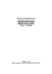
AR-B6005 Quick Manual
Download - Acrosser
Download - Acrosser

Create successful ePaper yourself
Turn your PDF publications into a flip-book with our unique Google optimized e-Paper software.
<strong>AR</strong>-<strong>B6005</strong> <strong>Quick</strong> <strong>Manual</strong><br />
<strong>AR</strong>-<strong>B6005</strong> <strong>Quick</strong> <strong>Manual</strong><br />
<strong>AR</strong>-<strong>B6005</strong> <strong>Quick</strong> <strong>Manual</strong><br />
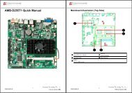
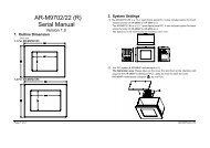
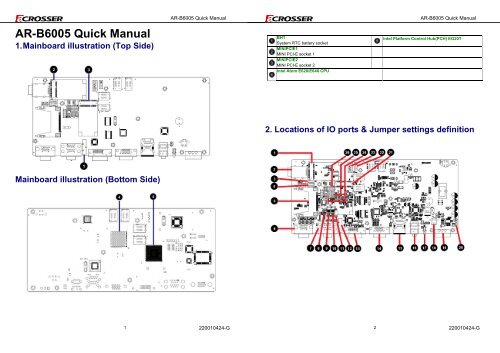
1. Mainboard illustration (Top Side)<br />
BH1<br />
System RTC battery socket<br />
MINIPCIE1<br />
MINI PCI-E socket 1<br />
MINIPCIE2<br />
MINI PCI-E socket 2<br />
Intel Atom E620/E640 CPU<br />
Intel Platform Control Hub(PCH) EG20T<br />
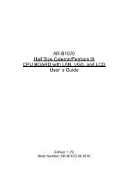
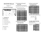
2. Locations of IO ports & Jumper settings definition<br />
Mainboard illustration (Bottom Side)<br />
1<br />
220010424-G<br />
2<br />
220010424-G
<strong>AR</strong>-<strong>B6005</strong> <strong>Quick</strong> <strong>Manual</strong><br />
<strong>AR</strong>-<strong>B6005</strong> <strong>Quick</strong> <strong>Manual</strong><br />
MINIPCIE1<br />
Mini-PCI Express Card connector<br />
COMBO1<br />
Combo connecter<br />
SIM1<br />
SIM card Holder<br />
CN4<br />
RJ45 & USB ports (USB1)Connector<br />
.<br />
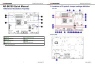
2.1 Connectors and Jumper Settings<br />
BT1<br />
Bluetooth module connector.<br />
GPS1<br />
GPS module connector.<br />
AUDIO1<br />
Line Out & Mic in ,Remote switch<br />
phone jack.<br />
LED2<br />
3 in 1 LED for Power, HDD, Status<br />
LED.<br />
1, 21. MINIPCIE1, MINIPCIE2 ( Mini-PCIe<br />
Connector )<br />
2. SIM1 Connector<br />
CF1<br />
CF C<strong>AR</strong>D SOCKET<br />
GPIO1<br />
D-SUB 15 pin for External GPIO<br />
connector.<br />
FUSE1<br />
For Fuse connector<br />
PWR2<br />
Power Input Terminal Block<br />
Connector<br />
Mini-PCIe x1 Connector<br />
SIM Card Holder<br />
Connects to 3.5G Cell phone<br />
SIM Card<br />
COM1_COM3<br />
D-SUB 9 pin for COM1,COM3 RS232<br />
connector<br />
SW1<br />
For RS-422,RS-485 function select.<br />
SW2<br />
For RS-422,RS-485 function select.<br />
SW3<br />
For RS-422,RS-485 function select.<br />
CCMOS1<br />
CMOS Memory Clearing Header<br />
BH1<br />
CR2032 Battery Hold Connector.<br />
DVI1<br />
DVI connecter<br />
PIC1<br />
PIC Programming connector.<br />
MINIPCIE2<br />
Mini-PCI Express Card connector<br />
SATA_PWR1<br />
For SATA Power Connector #1<br />
SATA1<br />
SATA device connector #1<br />
COM2_485<br />
Pin Header for COM2 use<br />
RS-422/485 function<br />
COM2<br />
Pin Header for COM2 use RS-232<br />
function<br />
SPI1<br />
BIOS Programmable HEADER.<br />
3,4. BT1, GPS1 5. CF1 (CF C<strong>AR</strong>D SOCKET)<br />
For Bluetooth ,GPS module connector.<br />
PIN SIGNAL<br />
1 +5V<br />
2 Data-<br />
3 Data+<br />
4 GND<br />
5 +3.3V<br />
6. GPIO1 (For External GPIO control)<br />
GPIO Pin Define:<br />
PIN SIGNAL PIN SIGNAL<br />
1 GPO0 2 GPO1<br />
3 GPO2 4 GPO3<br />
5 GND 6 GND<br />
7<br />
CAN_H<br />
8<br />
CAN_L<br />
9 GND 10<br />
i-Button<br />
11 GPI4 12 GPI5<br />
13 GPI6 14 GPI7<br />
15 VCC12A<br />
3<br />
220010424-G<br />
4<br />
220010424-G
<strong>AR</strong>-<strong>B6005</strong> <strong>Quick</strong> <strong>Manual</strong><br />
7. COM1_COM3 ( for COM1,COM3 use ) 8. SW1 ( RS-422,RS-485 function select )<br />
11. CCMOS1 12. BH1 (Battery Holder)<br />
CMOS Backup Battery:<br />
<strong>AR</strong>-<strong>B6005</strong> <strong>Quick</strong> <strong>Manual</strong><br />
Pin<br />
SIGNAL<br />
1 DCD<br />
2 SIN<br />
3 SOUT<br />
4 DTR<br />
5 GND<br />
6 DSR<br />
7 RTS<br />
8 CTS<br />
9 RI<br />
9. SW2 ( RS-422/485 TX Terminator resistor<br />
selection )<br />
SW2 DIP Switch<br />
For RS-422/485 TX Terminator resistor<br />
selection)<br />
(Default: all OFF)<br />
SW1, DIP Switch<br />
For RS-422,RS-485 Function<br />
select(Default: All OFF For RS-232)<br />
RS-422 setting:<br />
1 OFF<br />
2 ON<br />
3 OFF<br />
4 ON<br />
RS-485 setting:<br />
1 ON<br />
2 ON<br />
3 OFF<br />
4 ON<br />
10. SW3 (RS-422 RX Terminator resistor<br />
selection)<br />
SW3 DIP Switch<br />
For RS-422 RX Terminator resistor<br />
selection)<br />
(Default: all OFF)<br />
An onboard battery saves the CMOS memory to keep<br />
the BIOS information stays on even after<br />
disconnected your system with power source.<br />
Nevertheless, this backup battery exhausts after<br />
some five years<br />
Once the error message like “CMOS BATTERY HAS<br />
FAILED” or “CMOS checksum error” displays on<br />
monitor, this backup battery is no longer functional<br />
and has to be renewed<br />
13. DVI1 14. COMBO1<br />
Pin 1<br />
TMDS Data2-<br />
Pin 2 TMDS Data2+<br />
Pin 3<br />
GND<br />
Pin 1 USB_Data-<br />
Pin 4<br />
TMDS Data4-<br />
Pin 2 USB_Data+<br />
Pin 5 TMDS Data4+<br />
Pin 3<br />
GND<br />
Pin 6<br />
DDC Clock<br />
Pin 4 +5V<br />
Pin 7<br />
DDC Data<br />
Pin 5<br />
GND<br />
Pin 8 Analog VSYNC<br />
Pin 6<br />
RED<br />
Pin 9<br />
TMDS Data1-<br />
Pin 7<br />
GREEN<br />
Pin 10 TMDS Data1+<br />
Pin 8<br />
BLUE<br />
Pin 11<br />
GND<br />
Pin 9<br />
HSYNC<br />
Pin 12 TMDS Data3-<br />
Pin 10<br />
VSYNC<br />
Pin 13 TMDS Data3+<br />
Pin 11 DDCCLK<br />
Pin 14 +5V<br />
Pin 12 +12V<br />
Pin 15<br />
GND<br />
Pin 13<br />
GND<br />
Pin 16 Hot Plug Detect<br />
Pin 14 AUDIO R<br />
Pin 17 TMDS Data0-<br />
Pin 15<br />
GND<br />
Pin 18 TMDS Data0+<br />
Pin 16<br />
NC<br />
Pin 19<br />
GND<br />
Pin 17 AUDIO L<br />
Pin 20 TMDS Data5-<br />
Pin 18<br />
NC<br />
Pin 21 TMDS Data5+<br />
Pin 19<br />
NC<br />
Pin 22<br />
GND<br />
Pin 20 DDCDATA<br />
Pin 23 TMDS Clock+<br />
Pin 24 TMDS Clock-<br />
5<br />
220010424-G<br />
6<br />
220010424-G
<strong>AR</strong>-<strong>B6005</strong> <strong>Quick</strong> <strong>Manual</strong><br />
<strong>AR</strong>-<strong>B6005</strong> <strong>Quick</strong> <strong>Manual</strong><br />
15. CN4 16. AUDIO1<br />
22. SATA_PWR1 23. SATA1 (SATA device connector #1)<br />
To connect SATA device:<br />
SATA_PWR1 SATA Device Power Connector<br />
1.Attach either end of the signal cable to the<br />
RJ45 Ethernet Connector with 1 port<br />
of External USB Connector<br />
Color<br />
Blue<br />
Green<br />
SIGNAL<br />
Remote Switch<br />
Line Out<br />
PIN SIGNAL<br />
1 +12V<br />
2 GND<br />
3 +3.3V<br />
SATA connector on motherboard<br />
Attach the other end to the SATA device.<br />
2. Attach the SATA power cable to the SATA<br />
Pink<br />
MIC IN<br />
4 +5V<br />
device and connect the other end<br />
from the power supply<br />
17. LED2 (Power State) 18. FUSE1 (Fuse connector)<br />
LED SIGNAL<br />
G PIC LED<br />
G HDD LED<br />
Y Power LED<br />
PIN DEFINE<br />
1,2 Fuse Out<br />
3,4 Fuse In<br />
19. PWR2 (Power Input Terminal Block<br />
Connector)<br />
20. PIC1 (PIC Programming connector)<br />
PIN<br />
DEFINE<br />
1 12V / 24V<br />
PIC programming connector<br />
2 IGN<br />
3 GND<br />
7<br />
220010424-G<br />
8<br />
220010424-G
<strong>AR</strong>-<strong>B6005</strong> <strong>Quick</strong> <strong>Manual</strong><br />
24, 25. COM2, COM2_485 (For COM2<br />
Function select)<br />
COM2: For RS-232 Function<br />
26. SPI1 (BIOS Programmable HEADER)<br />
Pin<br />
SIGNAL<br />
1 DSR<br />
2 DCD<br />
3 RTS<br />
4 SIN<br />
5 CTS<br />
6 SOUT<br />
7 RI<br />
8 DTR<br />
9 NC<br />
10 GND<br />
COM2_485: For RS-422,RS-485<br />
Function<br />
PIN DEFINE PIN DEFINE<br />
1 CS0 2 +3.3V<br />
3 MISO 4 HOLD<br />
5 WP 6 CLK<br />
Pin<br />
SIGNAL<br />
7 GND 8 MOSI<br />
9 N.C 10 N.C<br />
1 NC<br />
2 485_422_TX+<br />
3 NC<br />
4 485_422_TX-<br />
5 422_RX2-<br />
6 NC<br />
7 422_RX2+<br />
8 NC<br />
9 NC<br />
10 GND<br />
9<br />
220010424-G