AR-B6005 Quick Manual
Download - Acrosser
Download - Acrosser

You also want an ePaper? Increase the reach of your titles
YUMPU automatically turns print PDFs into web optimized ePapers that Google loves.
<strong>AR</strong>-<strong>B6005</strong> <strong>Quick</strong> <strong>Manual</strong><br />
<strong>AR</strong>-<strong>B6005</strong> <strong>Quick</strong> <strong>Manual</strong><br />
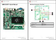
MINIPCIE1<br />
Mini-PCI Express Card connector<br />
COMBO1<br />
Combo connecter<br />
SIM1<br />
SIM card Holder<br />
CN4<br />
RJ45 & USB ports (USB1)Connector<br />
.<br />
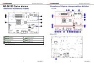
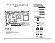
2.1 Connectors and Jumper Settings<br />
BT1<br />
Bluetooth module connector.<br />
GPS1<br />
GPS module connector.<br />
AUDIO1<br />
Line Out & Mic in ,Remote switch<br />
phone jack.<br />
LED2<br />
3 in 1 LED for Power, HDD, Status<br />
LED.<br />
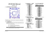
1, 21. MINIPCIE1, MINIPCIE2 ( Mini-PCIe<br />
Connector )<br />
2. SIM1 Connector<br />
CF1<br />
CF C<strong>AR</strong>D SOCKET<br />
GPIO1<br />
D-SUB 15 pin for External GPIO<br />
connector.<br />
FUSE1<br />
For Fuse connector<br />
PWR2<br />
Power Input Terminal Block<br />
Connector<br />
Mini-PCIe x1 Connector<br />
SIM Card Holder<br />
Connects to 3.5G Cell phone<br />
SIM Card<br />
COM1_COM3<br />
D-SUB 9 pin for COM1,COM3 RS232<br />
connector<br />
SW1<br />
For RS-422,RS-485 function select.<br />
SW2<br />
For RS-422,RS-485 function select.<br />
SW3<br />
For RS-422,RS-485 function select.<br />
CCMOS1<br />
CMOS Memory Clearing Header<br />
BH1<br />
CR2032 Battery Hold Connector.<br />
DVI1<br />
DVI connecter<br />
PIC1<br />
PIC Programming connector.<br />
MINIPCIE2<br />
Mini-PCI Express Card connector<br />
SATA_PWR1<br />
For SATA Power Connector #1<br />
SATA1<br />
SATA device connector #1<br />
COM2_485<br />
Pin Header for COM2 use<br />
RS-422/485 function<br />
COM2<br />
Pin Header for COM2 use RS-232<br />
function<br />
SPI1<br />
BIOS Programmable HEADER.<br />
3,4. BT1, GPS1 5. CF1 (CF C<strong>AR</strong>D SOCKET)<br />
For Bluetooth ,GPS module connector.<br />
PIN SIGNAL<br />
1 +5V<br />
2 Data-<br />
3 Data+<br />
4 GND<br />
5 +3.3V<br />
6. GPIO1 (For External GPIO control)<br />
GPIO Pin Define:<br />
PIN SIGNAL PIN SIGNAL<br />
1 GPO0 2 GPO1<br />
3 GPO2 4 GPO3<br />
5 GND 6 GND<br />
7<br />
CAN_H<br />
8<br />
CAN_L<br />
9 GND 10<br />
i-Button<br />
11 GPI4 12 GPI5<br />
13 GPI6 14 GPI7<br />
15 VCC12A<br />
3<br />
220010424-G<br />
4<br />
220010424-G