AR-B1666 INDUSTRIAL GRADE CPU BOARD User’s Guide
AR-B1666 INDUSTRIAL GRADE CPU BOARD User's ... - Acrosser
AR-B1666 INDUSTRIAL GRADE CPU BOARD User's ... - Acrosser
- No tags were found...

Create successful ePaper yourself
Turn your PDF publications into a flip-book with our unique Google optimized e-Paper software.
<strong>AR</strong>-<strong>B1666</strong> <strong>User’s</strong> <strong>Guide</strong><br />
<strong>AR</strong>-<strong>B1666</strong><br />
<strong>INDUSTRIAL</strong> <strong>GRADE</strong><br />
<strong>CPU</strong> BO<strong>AR</strong>D<br />
<strong>User’s</strong> <strong>Guide</strong><br />
Edition: 1.01<br />
Book Number: <strong>AR</strong>-<strong>B1666</strong>-04.0604<br />
1
<strong>AR</strong>-<strong>B1666</strong> <strong>User’s</strong> <strong>Guide</strong><br />
0. PREFACE .....................................................................................................................................................................3<br />
0.1 copyright notice and disclaimer............................................................................................................................3<br />
0.2 welcome to the <strong>AR</strong>-<strong>B1666</strong> cpu board...................................................................................................................3<br />
0.3 before you use this guide .....................................................................................................................................3<br />
0.4 Returning Your Board For Service........................................................................................................................3<br />
0.5 Technical Support And User Comments...............................................................................................................3<br />
0.6 Organization.........................................................................................................................................................4<br />
0.7 Static Electricity Precautions ................................................................................................................................4<br />
1. Introduction ...................................................................................................................................................................5<br />
1.1 specifications........................................................................................................................................................6<br />
1.2 packing list ...........................................................................................................................................................6<br />
2. setting up system ..........................................................................................................................................................7<br />
2.1 <strong>AR</strong>-<strong>B1666</strong> OVERVIEW ........................................................................................................................................7<br />
2.2 SYSTEM settings.................................................................................................................................................8<br />
2.2.1 Keyboard & Mouse Connector (KB1).........................................................................................................8<br />
2.2.2 SDRAM SOCKET 144 PIN (DIMM1)..........................................................................................................8<br />
2.2.3 Hard Disk (IDE) Connector (IDE1).............................................................................................................9<br />
2.2.5 USB Connector (USB1) ...........................................................................................................................10<br />
2.2.6 Serial Port (COM1) ..................................................................................................................................10<br />
2.2.7 Fan Power Connector (FAN1)..................................................................................................................10<br />
2.2.8 Internal Buzzer (BUZ1) ............................................................................................................................ 11<br />
2.2.9 Power/HD LED (LED5) ............................................................................................................................ 11<br />
2.2.10 LAN LED (LED1, LED2, LED3, LED4)................................................................................................... 11<br />
2.2.11 Ethernet RJ-45 Connector (LAN1, LAN2, LAN3, LAN4)......................................................................... 11<br />
2.2.12 Reset Button (RST1)..............................................................................................................................12<br />
2.2.13 Power Connector (PWR1)......................................................................................................................12<br />
2.2.14 CRT Connector (CRT)............................................................................................................................12<br />
2.215 MINI PCI SLOT (PCI1)............................................................................................................................12<br />
2.2.16 GPIO PORT (GPIO1).............................................................................................................................13<br />
2.2.17 Compact Flash Slot (CF1)......................................................................................................................14<br />
2.2.18 CF Master/Slave Mode Select (J2) ........................................................................................................14<br />
2.2.19 Clear CMOS Jumper (JBAT1)................................................................................................................14<br />
3. BIOS CONSOLE .........................................................................................................................................................15<br />
3.1 BIOS SETUP OVERVIEW .................................................................................................................................15<br />
3.2 ADVANCED........................................................................................................................................................17<br />
3.3 Peripherals.........................................................................................................................................................18<br />
3.4 PC Health...........................................................................................................................................................19<br />
3.5 Boot....................................................................................................................................................................20<br />
3.6 EXIT...................................................................................................................................................................21<br />
3.7 BIOS UPDATE ...................................................................................................................................................21<br />
Appendix A. Address Mapping… ………………………………………………………………………………………………….22<br />
IOAddressMap… ………………………………………………………………………………………………………………22<br />
MeMoryMap… ………………………………………………………………………………………………………… ………..23<br />
Appendix b. INTERRUPT REQUEST (IRQ)… …………………………………………………………………………………..23<br />
2
<strong>AR</strong>-<strong>B1666</strong> <strong>User’s</strong> <strong>Guide</strong><br />
0. PREFACE<br />
0.1 COPYRIGHT NOTICE AND DISCLAIMER<br />
This document is copyrighted, 2004, by Acrosser Technology Co., Ltd. All rights are reserved. No part<br />
of this manual may be reproduced, copied, transcribed, stored in a retrieval system, or translated into<br />
any language or computer language in any form or by any means, such as electronic, mechanical,<br />
magnetic, optical, chemical, manual or other means without the prior written permission or original<br />
manufacturer.<br />
Acrosser Technology assumes no responsibility or warranty with respect to the content in this manual<br />
and specifically disclaims any implied warranty of merchantability or fitness for any particular purpose.<br />
Furthermore, Acrosser Technology reserves the right to make improvements to the products described<br />
in this manual at any times without notice. Such revisions will be posted on the Internet<br />
(WWW.ACROSSER.COM) as soon as possible.<br />
Possession, use, or copy of the software described in this publication is authorized only pursuant to<br />
valid written license from Acrosser or an authorized sub licensor.<br />
ACKNOWLEDGEMENTS<br />
Acrosser, AMI, IBM PC/AT, VIA, Windows95, Windows98, WindowsME, Windows2000, WindowsXP,<br />
MS-DOS… are registered trademarks.<br />
All other trademarks and registered trademarks are the property of their respective owners.<br />
0.2 WELCOME TO THE <strong>AR</strong>-<strong>B1666</strong> <strong>CPU</strong> BO<strong>AR</strong>D<br />
This guide introduces the Acrosser <strong>AR</strong>-<strong>B1666</strong> <strong>CPU</strong> Board.<br />
Use information provided in this manual describes this card’s functions and features. It also helps you<br />
start, set up and operate your <strong>AR</strong>-<strong>B1666</strong>. General system information can also be found in this<br />
publication.<br />
0.3 BEFORE YOU USE THIS GUIDE<br />
Please refer to the Chapter 2, “System Setting,” in this guide, if you have not already installed this<br />
<strong>AR</strong>-<strong>B1666</strong>. Check the packing list before you install and make sure the accessories are completely<br />
included.<br />
<strong>AR</strong>-<strong>B1666</strong> CD provides the newest information regarding the <strong>CPU</strong> card. Please refer to the files of<br />
the enclosed utility CD. It contains the modification and hardware & software information, and<br />
adding the description or modification of product function after manual printed.<br />
0.4 RETURNING YOUR BO<strong>AR</strong>D FOR SERVICE<br />
If your board requires any services, contact the distributor or sales representative from whom you<br />
purchased the product for service information. If you need to ship your board to us for service, be sure<br />
it is packed in a protective carton. We recommend that you keep the original shipping container for this<br />
purpose.<br />
You can help assure efficient servicing for your product by following these guidelines:<br />
1. Include your name, address, daytime telephone, facsimile number and E-mail.<br />
2. A description of the system configuration and/or software at the time of malfunction.<br />
3. A brief description of the problem occurred.<br />
0.5 TECHNICAL SUPPORT AND USER COMMENTS<br />
<strong>User’s</strong> comments are always welcome as they assist us in improving the quality of our products and<br />
the readability of our publications. They create a very important part of the input used for product<br />
enhancement and revision.<br />
We may use and distribute any of the information you provide in any way appropriate without incurring<br />
any obligation. You may, of course, continue to use the information you provide.<br />
If you have any suggestions for improving particular sections or if you find any errors on it, please send<br />
your comments to Acrosser Technology Co., Ltd. or your local sales representative and indicate the<br />
manual title and book number.<br />
Internet electronic mail to: Sales@acrosser.com<br />
acrosser@tp.globalnet.com.tw<br />
3
<strong>AR</strong>-<strong>B1666</strong> <strong>User’s</strong> <strong>Guide</strong><br />
0.6 ORGANIZATION<br />
This information for users covers the following topics (see the Table of Contents for a detailed listing):<br />
Chapter 1, “Introduction”, provides specifications and packing list.<br />
Chapter 2, “Setting Up System”, describes how to adjust the jumpers and the connector settings.<br />
Chapter 3, “Watchdog Timer”, describes watchdog timer setting and trigger.<br />
Chapter 4, “BIOS Console”, provides the BIOS settings options.<br />
0.7 STATIC ELECTRICITY PRECAUTIONS<br />
Before removing the board from its anti-static bag, read this section about static electricity precautions.<br />
Static electricity is a constant danger to computer systems. The charge that can build up in your body<br />
may be more than sufficient to damage integrated circuits on any PC board. It is, therefore, important to<br />
observe basic precautions whenever you use or handle computer components. Although areas with<br />
humid climates are much less prone to static build-up, it is always best to safeguard against accidents<br />
that may result in expensive repairs. The following measures should be sufficient to protect your<br />
equipment from static discharge:<br />
• Touch a grounded metal object to discharge the static electricity in your body (or ideally, wear a<br />
grounded wrist strap).<br />
• When unpacking and handling the board or other system components, place all materials on an<br />
anti-static surface.<br />
• Be careful not to touch the components on the board, especially the “golden finger” connectors on<br />
the bottom of the board.<br />
4
<strong>AR</strong>-<strong>B1666</strong> <strong>User’s</strong> <strong>Guide</strong><br />
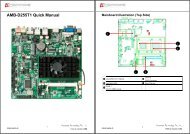
1. INTRODUCTION<br />
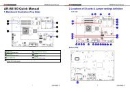
Welcome to the <strong>AR</strong>-<strong>B1666</strong> Single Board Computer. The <strong>AR</strong>-<strong>B1666</strong> board is Low power INTEL400ULV<br />
with the VIA ® advanced chipset Apollo PLE133T (VT8601T and VT82C686B). This product is<br />
designed for the system manufacturers, integrators, or V<strong>AR</strong>s that want to provide all the performance,<br />
reliability, and quality at a reasonable price.<br />
In addition, the <strong>AR</strong>-<strong>B1666</strong> provides on chip VGA. The VGA, which provides up to True Color (32 bit)<br />
1024x768 or High Color (16 bit) 1280x1024 resolutions. The VGA memory is share main memory (2M,<br />
4M, or 8M).<br />
The <strong>AR</strong>-<strong>B1666</strong> is loaded with special on-board features that rival full-size systems. It has four networks<br />
controller on board, uses National Semiconductor 83816 LAN controller, a fully integrated<br />
10/100BASE-TX solution with high performance networking functions. Compact Flash . MINIPCI. The<br />
<strong>AR</strong>-<strong>B1666</strong> also includes one 144-pin SO-DIMM sockets for up to 512 MB total on-board memory. The<br />
<strong>AR</strong>-<strong>B1666</strong> has two on-board serial ports; COM1 with RS232C, COM2 with RS232C, two USB<br />
connectors for 4 USB ports, watchdog timer and tough industrial grade construction. All these features<br />
make the <strong>AR</strong>-<strong>B1666</strong> a very "system integrator friendly" solution, perfect for handling applications in the<br />
harshest unmanned environments.<br />
INTEL<br />
400ULV<br />
10/100M<br />
83816<br />
RJ-45<br />
RJ-45<br />
10/100M<br />
83816<br />
PLE133T<br />
Chipset<br />
VT8601A<br />
North Bridge<br />
SODIMM<br />
x 1<br />
CRT<br />
PCI BUS<br />
IDE PORT<br />
MINIPCI x 1<br />
83816<br />
10/100M<br />
10/100M<br />
83816<br />
VT82C686B<br />
South<br />
Bridge<br />
CF C<strong>AR</strong>D<br />
2S<br />
Serial Port x2<br />
RJ-45<br />
RJ-45<br />
Keyboard<br />
ISA BUS<br />
PS/2 Mouse<br />
2 Port USB x 2<br />
BIOS<br />
39SF020<br />
GPIO<br />
<strong>AR</strong>-<strong>B1666</strong> System Block Diagram<br />
5
<strong>AR</strong>-<strong>B1666</strong> <strong>User’s</strong> <strong>Guide</strong><br />
1.1 SPECIFICATIONS<br />
• <strong>CPU</strong>: On-board INTEL 400 ULV<br />
• DMA channels: 7<br />
• Interrupt levels: 15<br />
• Chipset: VIA ® Apollo PLE133T (VT8601A Integrated 2D / 3D graphics accelerator and<br />
VT82C686B)<br />
• RAM memory: Supports SDRAM PC100, on-board 144-pin SO-DIMM up to 512MB SDRAM<br />
memory module<br />
• VGA Controller: Embedded VGA controller, Screen Resolution: up to True Color (32 bit)<br />
1024x768, or High Color (16 bit) 1280x1024.<br />
• Display Interface: CRT –2x5x2.00mm connector<br />
• Ultra ATA/33/66 IDE Interface: One PCI Enhance IDE channel. The south bridge VT82C686B<br />
supports Ultra ATA/33/66 IDE interface. To support Ultra ATA66 Hard disk, a specified cable must<br />
be available.<br />
• C. F.: Supports Compact Flash Type I interface<br />
• Series ports: On-board one D-SUB 9-pin male connector for COM1 with RS-232C.On-board one<br />
2x5x2.00mm pin-header connector for COM2 with RS-232C.(OPTION)<br />
• USB port: On-board one USB connector for 2 USB ports x 2.<br />
• Watchdog timer: Software programmable 1~63sec.<br />
• Ethernet: On-board Four National Semiconductor 83816, supports 10/100Mbps Base-T with<br />
RJ-45 connector built-in LED<br />
• K/B & Mouse: On-board PS/2 Keyboard and Mouse connector<br />
• GP I/O: On-board 1x6x2.00mm pin-header connector for 4-bit input and 4-bit output, TTL level<br />
• Power Req.: +5V 4A and +12V 1A maximum<br />
• PC Board: 4 layers, EMI considered<br />
• Dimensions: 203 mm x 146 mm<br />
• Operating Temperature: 0° ~ 60<br />
1.2 PACKING LIST<br />
These accessories are included with the system. Before you begin installing your <strong>AR</strong>-<strong>B1666</strong> board,<br />
please make sure that the following items have been included inside the <strong>AR</strong>-<strong>B1666</strong> package.<br />
• The quick setup manual<br />
• 1 <strong>AR</strong>-<strong>B1666</strong> <strong>CPU</strong> board<br />
• 1 Hard disk drive adapter cable for 2.5” hard disk<br />
• 1 Software utility CD<br />
• 1 RS-232 (option) and 1 PS/2 Mouse & Keyboard interface cable mounted on bracket<br />
• 1 VGA cable<br />
• 1 Mini Din power adapter & cable<br />
6
<strong>AR</strong>-<strong>B1666</strong> <strong>User’s</strong> <strong>Guide</strong><br />
2. SETTING UP SYSTEM<br />
This chapter describes how to install the <strong>AR</strong>-<strong>B1666</strong>. At first, the layout of <strong>AR</strong>-<strong>B1666</strong> is shown, and the<br />
unpacking information that you should be careful is described.<br />
• Overview<br />
• System Settings<br />
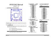
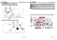
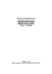
2.1 <strong>AR</strong>-<strong>B1666</strong> OVERVIEW<br />
TOP PLACEMENT<br />
BOTTOM PLACEMENT<br />
7
<strong>AR</strong>-<strong>B1666</strong> <strong>User’s</strong> <strong>Guide</strong><br />
2.2 SYSTEM SETTINGS<br />
Jumper pins allow you to set specific system parameters. Set them by changing the pin location of the<br />
jumper blocks. (A jumper block is a small plastic-encased conductor that slips over the pins.) To<br />
change a jumper setting, remove the jumper from its current location with your fingers or small<br />
needle-nosed pliers. Place the jumper over the two pins designated for the desired setting. Press<br />
the jumper evenly onto the pins. Be careful not to bend the pins.<br />
We will show the locations of the <strong>AR</strong>-<strong>B1666</strong> jumper pins, and the factory-default settings.<br />
CAUTION: Do not touch any electronic components unless you are safely grounded. Wear a grounded<br />
wrist strap or touch an exposed metal part of the system unit chassis. The static discharges from your<br />
fingers can permanently damage electronic components.<br />
2.2.1 Keyboard & Mouse Connector (KB1)<br />
The KB1 is a 6-pin pin header keyboard & Mouse connector. This keyboard & Mouse connector is<br />
PS/2 type connector. This connector is also for a standard IBM-compatible keyboard when used with<br />
the included PS/2 keyboard & Mouse adapter cable.<br />
`<br />
KB<br />
1<br />
6<br />
Pin #<br />
Signal Name<br />
1 MOUSE DATA<br />
2 KB DATA<br />
3 GND<br />
4 VCC<br />
5 MOUSE CLOCK<br />
6 KB CLOCK<br />
2.2.2 SDRAM SOCKET 144 PIN (DIMM1)<br />
It can assemble 16/32/64/128/256/512MB 144 pin DIMM Module Memory. When you set up 144-pin<br />
DIMM Module Memory, <strong>AR</strong>-<strong>B1666</strong> will auto-detect DRAM, and adopt correct save in order to make<br />
memory work till the best situation.<br />
Caution: Set up 144-pin DIMM Module Memory, please insert into slot vertical, if the direction is wrong<br />
and it leads to failure, please confirm the direction is right.<br />
DRAM Configuration (DIMM1)<br />
11144<br />
144 pin SO-DIMM<br />
8
<strong>AR</strong>-<strong>B1666</strong> <strong>User’s</strong> <strong>Guide</strong><br />
2.2.3 Hard Disk (IDE) Connector (IDE1)<br />
44 Pin Hard Disk Connector (IDE1)<br />
The on-board 44-pin mini-pitched IDE interface is used to let user support either a 3.5" HDD with<br />
44 to 40pin adapter cable.<br />
2 44<br />
1 43<br />
Pin Signal Pin Signal<br />
1 -RESET 2 GROUND<br />
3 DATA 7 4 DATA 8<br />
5 DATA 6 6 DATA 9<br />
7 DATA 5 8 DATA 10<br />
9 DATA 4 10 DATA 11<br />
11 DATA 3 12 DATA 12<br />
13 DATA 2 14 DATA 13<br />
15 DATA 1 16 DATA 14<br />
17 DATA 0 18 DATA 15<br />
19 GROUND 20 NOT USED<br />
21 IDEDREQ 22 GROUND<br />
23 -IOW A 24 GROUND<br />
25 -IOR A 26 GROUND<br />
27 IDEIORDYA 28 GROUND<br />
29 -DACKA 30 GROUND<br />
31 AINT 32 GROUND<br />
33 SA 1 34 Not Used<br />
35 SA 0 36 SA 2<br />
37 CS 0 38 CS 1<br />
39 HD LED A 40 GROUND<br />
41 VCC 42 VCC<br />
43 GROUND 44 Not Used<br />
2.2.4 CRT Connector (VGA1)<br />
VGA1 is a standard 10-pin header connector commonly used for VGA.<br />
2 10<br />
1 9<br />
Pin # Signal Name Pin # Signal Name<br />
1 RED 6 AGND<br />
2 AGND 7 V.S<br />
3 GREEN 8 DDCD<br />
4 GND 9 H.S<br />
5 BLUE 10 DDCK<br />
9
<strong>AR</strong>-<strong>B1666</strong> <strong>User’s</strong> <strong>Guide</strong><br />
2.2.5 USB Connector (USB1)<br />
The Universal Serial Bus (USB) controller is USB V1.1 and Universal HCI V1.1 compliant. The<br />
Universal Serial Bus (USB) standard is a low-to-medium speed interface for the connection of PC<br />
peripherals, which gives complete Plug & Play, and hot attach/detach for up to 127 external devices.<br />
USB is a leading edge technology that allows the user to quickly and easily add a wide range of<br />
peripheral devices from printers to keyboards and telephony devices to fax/modems. Universal Host<br />
Controller Interface (UHCI) and future support for the Open Host Controller Interface (OHCI) ensure<br />
USB compatibility and usability well into the future.<br />
The <strong>CPU</strong> board supports two Universal Serial Bus ports. If the USB ports are installed, the USB<br />
Controller line in the Integrated Peripherals section of the CMOS Setup utility must be set to “Enabled”.<br />
USB ports may also require Operating System support for USB devices.<br />
• USB1<br />
5 6 7 8 1.VCC<br />
1 2 3 4<br />
2.DATA0+ 6.DATA1+<br />
3.DATA0-<br />
4.GND<br />
5.VCC<br />
7.DATA1-<br />
8.GND<br />
2.2.6 Serial Port (COM1)<br />
<strong>AR</strong>-<strong>B1666</strong> is equipped with two serial ports. COM1 is a standard RS-232 interface.<br />
A. COM1<br />
USED RS232<br />
COM1<br />
1<br />
2<br />
3<br />
4<br />
5<br />
6<br />
7<br />
8<br />
9<br />
1.DCD<br />
2.DSR<br />
3.RX<br />
4.RTS<br />
5.TX<br />
6.CTS<br />
7.DTR<br />
8.RI<br />
9.GND<br />
2.2.7 Fan Power Connector (FAN1)<br />
FAN1 is 3-pin header for the <strong>CPU</strong> fan. The fan must be a 12V fan.<br />
<br />
<br />
<br />
<br />
10
<strong>AR</strong>-<strong>B1666</strong> <strong>User’s</strong> <strong>Guide</strong><br />
2.2.8 Internal Buzzer (BUZ1)<br />
1+ 2-<br />
2.2.9 Power/HD LED (LED5)<br />
1<br />
2<br />
1: Power LED<br />
2: HDD LED<br />
Power LED: External LED connector for Power status indication.<br />
HDD LED (IDE1): External LED connector for primary IDE channel.<br />
2.2.10 LAN LED (LED1, LED2, LED3, LED4)<br />
1 1:ACTIVE<br />
2 2:10/100M<br />
2.2.11 Ethernet RJ-45 Connector (LAN1, LAN2, LAN3, LAN4)<br />
The system supports onboard network connectivity. To utilize this function, install the network driver<br />
from the utility diskette, and connect the cable to the following RJ-45 header.<br />
8 1<br />
PIN (CN8) FUNCTION<br />
1 TPTX+<br />
2 TPTX -<br />
3 TPRX+<br />
4 Not Used<br />
5 Not Used<br />
6 TPRX-<br />
7 Not Used<br />
8 Not Used<br />
11
<strong>AR</strong>-<strong>B1666</strong> <strong>User’s</strong> <strong>Guide</strong><br />
2.2.12 Reset Button (RST1)<br />
SW<br />
1 2<br />
SW PUSHBUTTON<br />
2.2.13 Power Connector (PWR1)<br />
The PWR2 is a 4-pin mini dim power connector.<br />
PWR1<br />
4<br />
GND<br />
4<br />
3<br />
+12<br />
3<br />
25<br />
GND<br />
2<br />
1<br />
+5V<br />
1<br />
POWER_JACK<br />
B:PWR2:<br />
1<br />
2<br />
3<br />
4<br />
1: +12V<br />
2: GND<br />
3: GND<br />
4: +5V<br />
C: POWER SWITCH(J1)<br />
Jumper<br />
Open<br />
Short<br />
Function<br />
OFF<br />
ON<br />
2.2.14 CRT Connector (CRT)<br />
<strong>AR</strong>-<strong>B1666</strong> built-in 10-pin VGA connector directly to your CRT monitor.<br />
2 10<br />
1 9<br />
1.RED<br />
3.GREEN<br />
5.BLUE<br />
7.VSYNC<br />
9.HSYNC<br />
2.GND<br />
4.GND<br />
6.GND<br />
8.SPCLK<br />
10.SPD<br />
2.215 MINI PCI SLOT (PCI1)<br />
On board one mini PCI slot (PCI1)<br />
12
<strong>AR</strong>-<strong>B1666</strong> <strong>User’s</strong> <strong>Guide</strong><br />
2.2.16 GPIO PORT (GPIO1)<br />
1.VCC3<br />
2.GPIOA<br />
3.GPIOB<br />
4.GPIOC<br />
5.GPIOD<br />
6.GND<br />
1 6<br />
Users could test GPIO function under ‘Debug’program as follow:<br />
GPO Example<br />
o 4e 87<br />
;Extended Functions Enable Register<br />
o 4e 87<br />
;Extended Functions Enable Register<br />
o 4e 29<br />
;select CR29<br />
o 4f 80 ;(Define the PINs as GPIO or Game Port 1)<br />
"80" Pin121 ~ 128 set as GPIO<br />
o 4e 07<br />
;EFIR=EFER (Extended Functions Index Register)<br />
point to Logical Device Number Reg.<br />
o 4f 07 ;EFDR=EFIR+1 (select logical device 7,GPIO in logical device 7 )<br />
o 4e 30<br />
;select CR30 (Active or inactive)<br />
o 4f 01<br />
;set 01 (Active) 00 (inactive)<br />
o 4e f0<br />
;select CRF0 (Set the PINs be GPO or GPI Function)<br />
o 4f 00<br />
;set the PINs be GPO<br />
o 4e f2<br />
;select CRF2 (Output High / Low)<br />
o 4f 00<br />
;set the PINs be all Low Level (FF=all High Level)<br />
o 4e f1<br />
;select CRF1<br />
o 4f 07 ;set the output to be 07<br />
o 4e aa<br />
q<br />
;exit EFER<br />
;Quit debug<br />
GPI Example<br />
o 4e 87<br />
;Extended Functions Enable Register<br />
o 4e 87<br />
;Extended Functions Enable Register<br />
o 4e 29<br />
;select CR29<br />
o 4f 80 ;(Define the PINs as GPIO or Game Port 1)<br />
"80" Pin121 ~ 128 set as GPIO<br />
o 4e 07<br />
;EFIR=EFER (Extended Functions Index Register)<br />
point to Logical Device Number Reg.<br />
o 4f 07 ;EFDR=EFIR+1 (select logical device 7,GPIO in logical device 7 )<br />
o 4e 30<br />
;select CR30 (Active or inactive)<br />
o 4f 01<br />
;set 01 (Active) 00 (inactive)<br />
o 4e f0<br />
;select CRF0 (Set the PINs be GPO or GPI Function)<br />
o 4f ff<br />
;set the PINs be GPI<br />
o 4e f1<br />
;select CRF1 (Set the PINs be Read only)<br />
i 4f<br />
;Show the PINs Value<br />
q<br />
;Quit debug<br />
13
<strong>AR</strong>-<strong>B1666</strong> <strong>User’s</strong> <strong>Guide</strong><br />
2.2.17 Compact Flash Slot (CF1)<br />
Pin assignment is showed below.<br />
2.2.18 CF Master/Slave Mode Select (J2)<br />
This 2-pins jumper will decide the CF operating in master/slave mode.<br />
Jumper<br />
Open (Factory Preset)<br />
Short<br />
Slave<br />
Master<br />
Function<br />
2.2.19 Clear CMOS Jumper (JBAT1)<br />
1 2 3<br />
Jumper<br />
Function<br />
(1-2) Keep Data (Factory Preset)<br />
(2-3) Clear Data<br />
14
<strong>AR</strong>-<strong>B1666</strong> <strong>User’s</strong> <strong>Guide</strong><br />
3. BIOS CONSOLE<br />
This chapter describes the <strong>AR</strong>-<strong>B1666</strong> BIOS menu displays and explains how to perform common tasks<br />
needed to get up and running, and presents detailed explanations of the elements found in each of the<br />
BIOS menu. The following topics are covered:<br />
• Main<br />
• Advanced<br />
• Peripherals<br />
• PC Health<br />
• Boot<br />
• Exit<br />
3.1 BIOS SETUP OVERVIEW<br />
The BIOS is a program used to initialize and set up the I/O system of the computer, which includes the<br />
ISA bus and connected devices such as the video display, diskette drive, and the keyboard.<br />
The BIOS provides a menu-based interface to the console subsystem. The console subsystem<br />
contains special software, called firmware that interacts directly with the hardware components and<br />
facilitates interaction between the system hardware and the operating system.<br />
The BIOS default values ensure that the system will function at its normal capability. In the worst<br />
situation the user may have corrupted the original settings set by the manufacturer.<br />
After the computer is turned on, the BIOS will perform diagnostics on the system and display the size of<br />
the memory that is being tested. Press the [Del] key to enter the BIOS Setup program, and then the<br />
main menu will show on the screen.<br />
The BIOS Setup main menu includes some options. Use the [Up/Down] arrow key to highlight the<br />
option that you wish to modify, and then press the [Enter] key to select the option and configure the<br />
functions.<br />
Main Menu<br />
The option allows you to record some basic system hardware configuration and set the system clock<br />
and error handling. If the <strong>CPU</strong> board is already installed in a working system, you will not need to select<br />
this option anymore.<br />
15
<strong>AR</strong>-<strong>B1666</strong> <strong>User’s</strong> <strong>Guide</strong><br />
Date & Time Setup<br />
Highlight the field and then press the [Page Up] /[Page Down] or [+]/[-] keys to set the current<br />
date. Follow the month, day and year format.<br />
Highlight the field and then press the [Page Up] /[Page Down] or [+]/[-] keys to set the current<br />
date. Follow the hour, minute and second format.<br />
The user can bypass the date and time prompts by creating an AUTOEXEC.BAT file. For information<br />
on how to create this file, please refer to the MS-DOS manual.<br />
Hard Disk Setup<br />
The BIOS supports various types for user settings, The BIOS supports , , and so the user can install up to two hard disks. For the master and slave<br />
jumpers, please refer to the hard disk’s installation descriptions and the hard disk jumper settings in<br />
section three of this manual.<br />
16
<strong>AR</strong>-<strong>B1666</strong> <strong>User’s</strong> <strong>Guide</strong><br />
3.2 ADVANCED<br />
The option consists of configuration entries that allow you to improve your system<br />
performance, or let you set up some system features according to your preference. Some entries here<br />
are required by the <strong>CPU</strong> board’s design to remain in their default settings.<br />
Advanced<br />
Quick Power on Self Test<br />
This field speeds up the Power-On-Self Test (POST) routine by skipping retesting a second, third, and<br />
fourth time. Configuration options: [Disabled][Enable]<br />
On Chip USB<br />
This option can enable USB Ports or Disabled USB function.<br />
USB Keyboard Support<br />
This option can enable or Disabled USB keyboard function.<br />
USB Mouse Support<br />
This option can enable or Disabled USB mouse function.<br />
ACPI Function<br />
This item allows you to Enabled/Disabled the Advanced Configuration and Power Management (ACPI).<br />
The settings are Enabled and Disabled.<br />
ACPI Suspend Type<br />
This item will set which ACPI suspend type will be used.<br />
S1 (POS)<br />
The S1 sleeping state is low wake-up latency sleeping state. In this state, no system context is lost<br />
(<strong>CPU</strong> or chipset) and hardware maintains all system contexts.<br />
S3 (STR)<br />
The S3 state is low wake-up latency sleeping sates and all system contexts are lost expecting system<br />
memory. <strong>CPU</strong>, cache, and chipset context are lost in this state. Hardware maintains memory context<br />
and restores some <strong>CPU</strong> and L2 configuration context.<br />
17
<strong>AR</strong>-<strong>B1666</strong> <strong>User’s</strong> <strong>Guide</strong><br />
State after Power Failure<br />
This option enables the End User to define if the system will be power-on once the AC Power is given.<br />
The Options:<br />
1. Power Off (Always Power Off, must press Power Button to boot)<br />
2. Power On (Auto Power On when AC power is on)<br />
3. Last State (Depend on the Last State of the system).<br />
3.3 PERIPHERALS<br />
This option controls the configuration of the board’s chipset. Control keys for this screen are the same<br />
as for the previous screen.<br />
Peripherals<br />
On Chip IDE Channel0<br />
On Chip IDE Channel1<br />
The chipset contains a PCI IDE interface with support for two IDE channels. Select Enabled to activate<br />
the first and/or second IDE interface. Select Disabled to deactivate an interface, if you install a primary<br />
and/or secondary add-in IDE interface.<br />
Onboard Serial Port<br />
These fields allow you to set the addresses for the onboard serial connectors. Serial Port 1 and Serial<br />
Port 2 must have different addresses.<br />
Configuration Options:[Disabled][3F8/IRQ4][2F8/IRQ3][3E8/IRQ4][2E8/IRQ3][Auto]<br />
U<strong>AR</strong>T 2 Mode<br />
Select an operating mode for the second serial port:<br />
Standard RS-232C serial port<br />
HPSIR<br />
ASK IR<br />
IrDA-compliant serial infrared port<br />
Amplitude shift keyed infrared port<br />
18
<strong>AR</strong>-<strong>B1666</strong> <strong>User’s</strong> <strong>Guide</strong><br />
3.4 PC HEALTH<br />
This section is used to configure power management features. This <br />
option allows you to reduce power consumption. This feature turns off the video display and shuts<br />
down the hard disk after a period of inactivity.<br />
Current <strong>CPU</strong> Temp.<br />
The onboard hardware monitor automatically detects and displays the <strong>CPU</strong> temperatures.<br />
Current <strong>CPU</strong>FAN1 Speed<br />
The onboard hardware monitor automatically detects and displays the <strong>CPU</strong> fan Speeds in rotations<br />
per-minute (RPM). If any of the fans is not connected to the Motherboard, that field shows N/A.<br />
19
<strong>AR</strong>-<strong>B1666</strong> <strong>User’s</strong> <strong>Guide</strong><br />
3.5 BOOT<br />
First Boot Device [CDROM]<br />
This field sets the priority of the first boot device; by default, the system boots up on The CD-ROM drive.<br />
Configuration options: [Floppy] [LS120] [HDD][SCSI] [CDROM] [ZIP100] [USB-FDD] [USB-Zip]<br />
[USB-CDROM] [USB-HDD] [LAN] [Disabled]<br />
Second Boot Device [HDD]<br />
This field sets the priority of the second boot device; by default, the system boots up on the hard disk<br />
drive if the CD-ROM drive is not present. Configuration options: [Floppy] [LS120] [HDD][SCSI]<br />
[CDROM] [ZIP100] [USB-FDD] [USB-Zip] [USB-CDROM] [USB-HDD] [LAN] [Disabled]<br />
Third Boot Device [USB-FDD]<br />
This field sets the priority of the third boot device; by default, the system boots up on the USB-FDD<br />
drive if the CD-ROM drive and hard disk drive is not present. Configuration options: [Floppy] [LS120]<br />
[HDD][SCSI] [CDROM] [ZIP100] [USB-FDD] [USB-Zip] [USB-CDROM] [USB-HDD] [LAN] [Disabled]<br />
Boot Other Device [Enabled]<br />
By default, this field enables the detection of the other device, by default, aside from the first three<br />
priority devices. Configuration options: [Enabled] [Disabled]<br />
20
<strong>AR</strong>-<strong>B1666</strong> <strong>User’s</strong> <strong>Guide</strong><br />
3.6 EXIT<br />
This section is used to configure peripheral features.<br />
Save & Exit Setup<br />
Type “Y” will quit the Setup Utility and save the user setup value to RTC CMOS. Type “N” will return to<br />
Setup Utility.<br />
Load BIOS Defaults<br />
Selecting this field loads the factory defaults for BIOS and Chipset Features, which the System<br />
automatically detects.<br />
Exit Without Saving<br />
Type “Y” will quit the Setup Utility without saving to RTC CMOS.<br />
Type “N” will return to Setup Utility.<br />
3.7 BIOS UPDATE<br />
The BIOS program instructions are contained within computer chips called FLASH ROMs that are<br />
located on your system board. The chips can be electronically reprogrammed, allowing you to<br />
upgrade your BIOS firmware without removing and installing chips.<br />
The <strong>AR</strong>-<strong>B1666</strong> provides the FLASH BIOS update function for you to easily to update to a newer BIOS<br />
version. Please follow these operating steps to update to new BIOS:<br />
Step 1:<br />
Step 2:<br />
Step 3:<br />
Turn on your system and don’t detect the CONFIG.SYS and AUTOEXEC.BAT files.<br />
Insert the FLASH BIOS diskette into the floppy disk drive.<br />
In the MS-DOS mode, you can type the AWDFLASH program.<br />
A:\>Awdflash filename. bin /py /sn /f<br />
21
<strong>AR</strong>-<strong>B1666</strong> <strong>User’s</strong> <strong>Guide</strong><br />
APPENDIX A. ADDRESS MAPPING<br />
IO Address Map<br />
I/O MAP<br />
0x0000-0x0CF7<br />
0x0000-0x0CF7<br />
0x0D00-0x3FFF<br />
0x4100-0x4FFF<br />
0x5010-0x5FFF<br />
0x6080-0xFFFF<br />
0x03B0-0x03BB<br />
0x03B0-0x03BB<br />
0x03C0-0x03DF<br />
0x03C0-0x03DF<br />
0x0A79-0x0A79<br />
0x0279-0x0279<br />
0x0274-0x0277<br />
0xE000-0xE00F<br />
0x01F0-0x01F7<br />
0x03F6-0x03F6<br />
0x0170-0x0177<br />
0x0376-0x0376<br />
0xE100-0xE11F<br />
0xE200-0xE21F<br />
0xFE00-0xFEFF<br />
0xE400-0xE4FF<br />
0xE500-0xE5FF<br />
0xE600-0xE6FF<br />
0x0010-0x001F<br />
0x0022-0x003F<br />
0x0044-0x005F<br />
0x0062-0x0063<br />
0x0065-0x006F<br />
0x0074-0x007F<br />
0x0091-0x0093<br />
0x00A2-0x00BF<br />
0x00E0-0x00EF<br />
0x04D0-0x04D1<br />
0x0020-0x0021<br />
0x00A0-0x00A1<br />
0x0080-0x0090<br />
0x0094-0x009F<br />
0x00C0-0x00DF<br />
0x0040-0x0043<br />
0x0070-0x0073<br />
0x0061-0x0061<br />
0x00F0-0x00FF<br />
0x03F8-0x03FF<br />
0x02F8-0x02FF<br />
0x0060-0x0060<br />
0x0064-0x0064<br />
ASSIGNMENT<br />
PCI bus<br />
Direct memory access controller<br />
PCI bus.<br />
PCI bus<br />
PCI bus<br />
PCI bus<br />
VIA Tech <strong>CPU</strong> to AGP Controller<br />
VIA Tech VT8361/VT8601 Graphics Controller<br />
VIA Tech <strong>CPU</strong> to AGP Controller<br />
VIA Tech VT8361/VT8601 Graphics Controller<br />
ISAPNP Read Data Port<br />
ISAPNP Read Data Port<br />
ISAPNP Read Data Port<br />
VIA Bus Master IDE Controller<br />
Primary IDE Channel<br />
Primary IDE Channel<br />
Secondary IDE Channel<br />
Secondary IDE Channel<br />
VIA USB Universal Host Controller<br />
VIA USB Universal Host Controller<br />
National Semiconductor Corp. DP83815/816 10/100 MacPhyter PCI<br />
Adapter<br />
National Semiconductor Corp. DP83815/816 10/100 MacPhyter PCI<br />
Adapter #2<br />
National Semiconductor Corp. DP83815/816 10/100 MacPhyter PCI<br />
Adapter #3<br />
National Semiconductor Corp. DP83815/816 10/100 MacPhyter PCI<br />
Adapter #4<br />
Motherboard resources<br />
Motherboard resources<br />
Motherboard resources<br />
Motherboard resources<br />
Motherboard resources<br />
Motherboard resources<br />
Motherboard resources<br />
Motherboard resources<br />
Motherboard resources<br />
Motherboard resources<br />
Programmable interrupt controller<br />
Programmable interrupt controller<br />
Direct memory access controller<br />
Direct memory access controller<br />
Direct memory access controller<br />
System timer<br />
System CMOS/real time clock<br />
System speaker<br />
Numeric data processor<br />
Communications Port (COM1)<br />
Communications Port (COM2)<br />
Standard 101/102-Key or Microsoft Natural PS/2 Keyboard<br />
Standard 101/102-Key or Microsoft Natural PS/2 Keyboard<br />
22
<strong>AR</strong>-<strong>B1666</strong> <strong>User’s</strong> <strong>Guide</strong><br />
Memory Map:<br />
MEMORY MAP<br />
0xF0000-0xF3FFF<br />
0xF4000-0xF7FFF<br />
0xF8000-0xFBFFF<br />
0xFC000-0xFFFFF<br />
0x77F0000-0x77FFFFF<br />
0xFFFF0000-0xFFFFFFFF<br />
0x0000-0x9FFFF<br />
0x100000-0x77EFFFF<br />
0xFEE00000-0xFEE00FFF<br />
0xA0000-0xBFFFF<br />
0xA0000-0xBFFFF<br />
0xA0000-0xBFFFF<br />
0xC0000-0xDFFFF<br />
0x7800000-0xFFEFFFFF<br />
0xEC000000-0xED7FFFFF<br />
0xEC000000-0xED7FFFFF<br />
0xE8000000-0xEBFFFFFF<br />
0xED000000-0xED01FFFF<br />
0xEC800000-0xECFFFFFF<br />
0xED813000-0xED813FFF<br />
0xED810000-0xED810FFF<br />
0xED811000-0xED811FFF<br />
0xED812000-0xED812FFF<br />
ASSIGNMENT<br />
System board<br />
System board<br />
System board.<br />
System board<br />
System board<br />
System board<br />
System board<br />
System board<br />
System board<br />
PCI bus<br />
VIA <strong>CPU</strong> to AGP Controller<br />
VIA Tech VT8361/VT8601 Graphics Controller<br />
PCI bus<br />
PCI bus<br />
VIA <strong>CPU</strong> to AGP Controller<br />
VIA Tech VT8361/VT8601 Graphics Controller<br />
VIA <strong>CPU</strong> to AGP Controller<br />
VIA Tech VT8361/VT8601 Graphics Controller<br />
VIA Tech VT8361/VT8601 Graphics Controller<br />
National Semiconductor Corp. DP83815/816 10/100<br />
MacPhyter PCI Adapter<br />
National Semiconductor Corp. DP83815/816 10/100<br />
MacPhyter PCI Adapter #2<br />
National Semiconductor Corp. DP83815/816 10/100<br />
MacPhyter PCI Adapter #3<br />
National Semiconductor Corp. DP83815/816 10/100<br />
MacPhyter PCI Adapter #4<br />
APPENDIX B. INTERRUPT REQUEST (IRQ)<br />
SETTING H<strong>AR</strong>DW<strong>AR</strong>E USING THE SETTING<br />
01 Standard 101/102-Key or Microsoft Natural PS/2 Keyboard<br />
03 Communications Port (COM2)<br />
04 Communications Port (COM1)<br />
07 VIA Tech VT8361/VT8601 Graphics Controller<br />
07 VIA USB Universal Host Controller<br />
07 VIA USB Universal Host Controller<br />
07 National Semiconductor Corp. DP83815/816 10/100 MacPhyter PCI Adapter<br />
07 National Semiconductor Corp. DP83815/816 10/100 MacPhyter PCI Adapter #2<br />
07 National Semiconductor Corp. DP83815/816 10/100 MacPhyter PCI Adapter #3<br />
07 National Semiconductor Corp. DP83815/816 10/100 MacPhyter PCI Adapter #4<br />
08 System CMOS/real time clock<br />
09 Microsoft ACPI-Compliant System<br />
12 PS/2 Compatible Mouse<br />
13 Numeric data processor<br />
14 Primary IDE Channel<br />
23