SMALL DAMS
SMALL DAMS - Comité Français des Barrages et Réservoirs
SMALL DAMS - Comité Français des Barrages et Réservoirs
- No tags were found...

You also want an ePaper? Increase the reach of your titles
YUMPU automatically turns print PDFs into web optimized ePapers that Google loves.
Chapter IV<br />
PROTECTION OF FACES AND CREST<br />
Placing a layer of gravel on the crest will in particular avoid the formation of ruts due<br />
to traffic and desiccation of the last layers of compacted clay materials.<br />
The dimensions of the protection for the upstream slope (including the filter blanket)<br />
should take into account the effect of waves and the type of protection selected.<br />
ICOLD Bulletin 91, published in June 1993, specifically deals with protection of<br />
upstream slopes for fill dams and the reader is invited to consult it.<br />
That bulletin gives rules for dimensioning rip-rap protection (median block mass,<br />
grading, thickness of the layer, thickness and grading of the filter blanket, material<br />
quality). It also describes in detail specifications concerning protections made of:<br />
!" soil-cement;<br />
!" cast-on-site concrete slabs;<br />
!" pre-cast concrete blocks;<br />
!" bituminous concrete.<br />
Wave action depends essentially on reservoir size and geographical location (wind<br />
rose). The choice of type of protection and its dimensions are therefore independent<br />
of dam height. From this standpoint, small dams cannot be considered as special<br />
cases unless the reservoir surface area is small.<br />
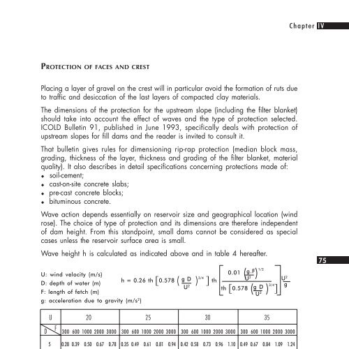
Wave height h is calculated as indicated above and in table 4 hereafter.<br />
U: wind velocity (m/s)<br />
D: depth of water (m)<br />
F: length of fetch (m)<br />
g: acceleration due to gravity (m/s 2 )<br />
h = 0.26 th 0.578 (<br />
g D<br />
) 3/4 <br />
U 2<br />
0.01<br />
U2<br />
th<br />
(<br />
g.F<br />
) 1/2<br />
U 2<br />
th 0.578 (<br />
g D<br />
) 3/4 g<br />
<br />
U 2<br />
75<br />
D<br />
U 20 25 30 35<br />
F<br />
300 600 1000 2000 3000 300 600 1000 2000 3000 300 600 1000 2000 3000 300 600 1000 2000 3000<br />
5 0.28 0.39 0.50 0.67 0.78 0.35 0.49 0.61 0.81 0.94 0.42 0.58 0.73 0.96 1.10 0.49 0.67 0.84 1.09 1.24<br />
10 0.29 0.40 0.51 0.71 0.86 0.36 0.50 0.64 0.88 1.06 0.43 0.60 0.76 1.05 1.25 0.50 0.70 0.89 1.21 1.44<br />
15 0.29 0.40 0.52 0.73 0.88 0.36 0.50 0.65 0.90 1.09 0.43 0.60 0.77 1.08 1.30 0.50 0.70 0.90 1.25 1.50<br />
20 0.29 0.40 0.52 0.73 0.89 0.36 0.51 0.65 0.91 1.11 0.43 0.61 0.78 1.09 1.32 0.50 0.71 0.91 1.27 1.53<br />
25 0.29 041 0.52 0.73 0.89 0.36 0.51 0.65 0.92 1.11 0.43 0.61 0.78 1.10 1.33 0.50 0.71 0.91 1.28 1.55<br />
Table 4 - Wave height h expressed in metres<br />
Depending on wave height h, table 5 gives the recommended dimensions for classic<br />
rip-rap: thickness e of the rockfill layer (measured perpendicularly to the face) and<br />
diameter d 50<br />
such that 50% of the blocks by weight have a diameter equal to or<br />
greater than d 50<br />
. The dimensions of the largest blocks are limited to e. The smallest<br />
elements should not have a diameter less than 0.10 metre.